Amphenol Socapex RESMLAC-12EMG-F35 Instructions for use

RESMLAC
12E
MG
F35
-
UM
rev.
1
Page
1
/
16
www.amphenol-socapex.com
Tel: +33(0)4.50.89.28.00
IP67 rugged Ethernet Managed Switch
RESMLAC-12EMG-F35
-
ardware
User Manual
-
Contents
Section 1
General Information
Page 3
Section
2
Hardware
Page
4
Section
3
Installation
Page
5
Section
4
Wiring
Page
7
Section 5
Management
Page
1
2
Section
6
Features Overview
Page
1
3
Section
7
Service Information
Page 1
6
This manual applies to the following products:
•RESMLAC 12EMG F35 (options)
Rugged IP67 Managed Ethernet Switch, with 12 gigabit port, all LAN ports
shared within two MIL-DTL-38999 connectors.
Revision Date Modifications
1
August
20
2
2
Initial docu
men
t

RESMLAC
12E
MG
F35
-
UM
rev.
1
Page
2
/
16
www.amphenol-socapex.com
Tel: +33(0)4.50.89.28.00
AMPHENOL SOCAPEX GENERAL CONDITIONS OF SALE
(Effective as at 28th/09/2020)
(EXTRACT)
ARTICLE 11: GUARANTEE - LIABILITY
11.1. Products shall benefit from a legal guarantee of one year following the date of delivery in accordance with the terms and
conditions indicated hereunder.
11.2. In all instances, Seller’s guarantee shall be limited to free replacement, in identical quantities, of the Product
acknowledged as defective by Seller with the exclusion of any compensation or damages and interests and subject that Client
notifies Seller of defect immediately following discovery thereof by any written means during the legal guarantee period.
Defective Products shall be returned to Seller in accordance with the same procedure as that applicable to Products which do
not comply with orders as indicated under article 9 hereinabove.
11.3 The following shall be excluded from the guarantees provided by Seller:
-
Product defects resulting from inadequate maintenance, or supervision and, more widely, any use which does not comply with
written instructions of Seller and indicated in technical notices and/or product specifications, or default in respecting applicable
standards or professional customs and uses;
-
Product defects resulting from an external cause or any modification or intervention by Client or third party without the prior
written consent of Seller;
-
the guarantee shall not cover normal wear and tear of Products ;
-
Product defects resulting generally in whole or in part from damage or accidents attributable to Client or a third party;
-
the guarantee shall not cover any defects resulting from instructions given by Client to Seller ;
-
damages resulting from force majeure, such as this is defined under article 11 hereunder, or resulting from any unpredictable
event or natural disaster.
Client shall retain sole and exclusive liability for the use of Products provided by Seller and the suitability thereof for use.
Client should ensure that its premises and storage conditions are adequate for the due and proper storage of Products and ensure
all safety guarantees as stipulated by regulations in force. No guarantee shall be provided by Seller in this regard.
In all instances and under no circumstances whatsoever shall Seller be liable for any damage, whether direct or indirect, or
predictable or not, caused by any defect of the Product sold. In this regard, no compensation may be claimed.
Note: All information in this document is subject to change without notice.

RESMLAC
12E
MG
F35
-
UM
rev.
1
Page
3
/
16
www.amphenol-socapex.com
Tel: +33(0)4.50.89.28.00
Section 1
General Information
Overview
This manual will help you install and maintain the Amphenol Rugged Ethernet Managed
switches. These products are extremely easy to install and operate.
Military applications can now take full advantage of 1000Mbps Gigabit Ethernet
performance.
The installation guide describes how to install and use the hardened compact Ethernet
RESMLAC-12EMG-F35 Military Rugged Switch. Capable of operating at extreme
temperature of -45°C to +80°C and meet the toughest industrial and military environments
such as MIL-STD-810F/G/GM, MIL-STD-1275, MIL-STD-461E up to the highest levels.
The mentioned ability turns the RESMLAC-12EMG-F35 to the optimal solutions switch of
choice for harsh environments constrained by space.
Developed for military and harsh mobile applications, the RESMLAC-12EMG-F35
features mechanical packaging enhancements designed for MIL-STD-810F/G/GM airborne
and ground environmental compliance and high reliability. The unit has been especially
hardened to improve ingress, impact, and shock/vibration protection, as well as eliminate
all moving parts through passive cooling, and interface through sealed MIL-D-38999
circular connectors.
Leveraging best-in-class switching technology, the RESMLAC-12EMG-F35 serves as a
robust solution for providing local area network (LAN) connectivity to IP-enabled
computing and net-centric devices. Compact in size, the RESMLAC-12EMG-F35 is
particularly useful for expanding port density to tactical IP routers in space-constrained
airborne and ground vehicle environments.
Performance
Specifications
These general specifications apply to these switches. Refer to Section 6 for complete
technical specifications.
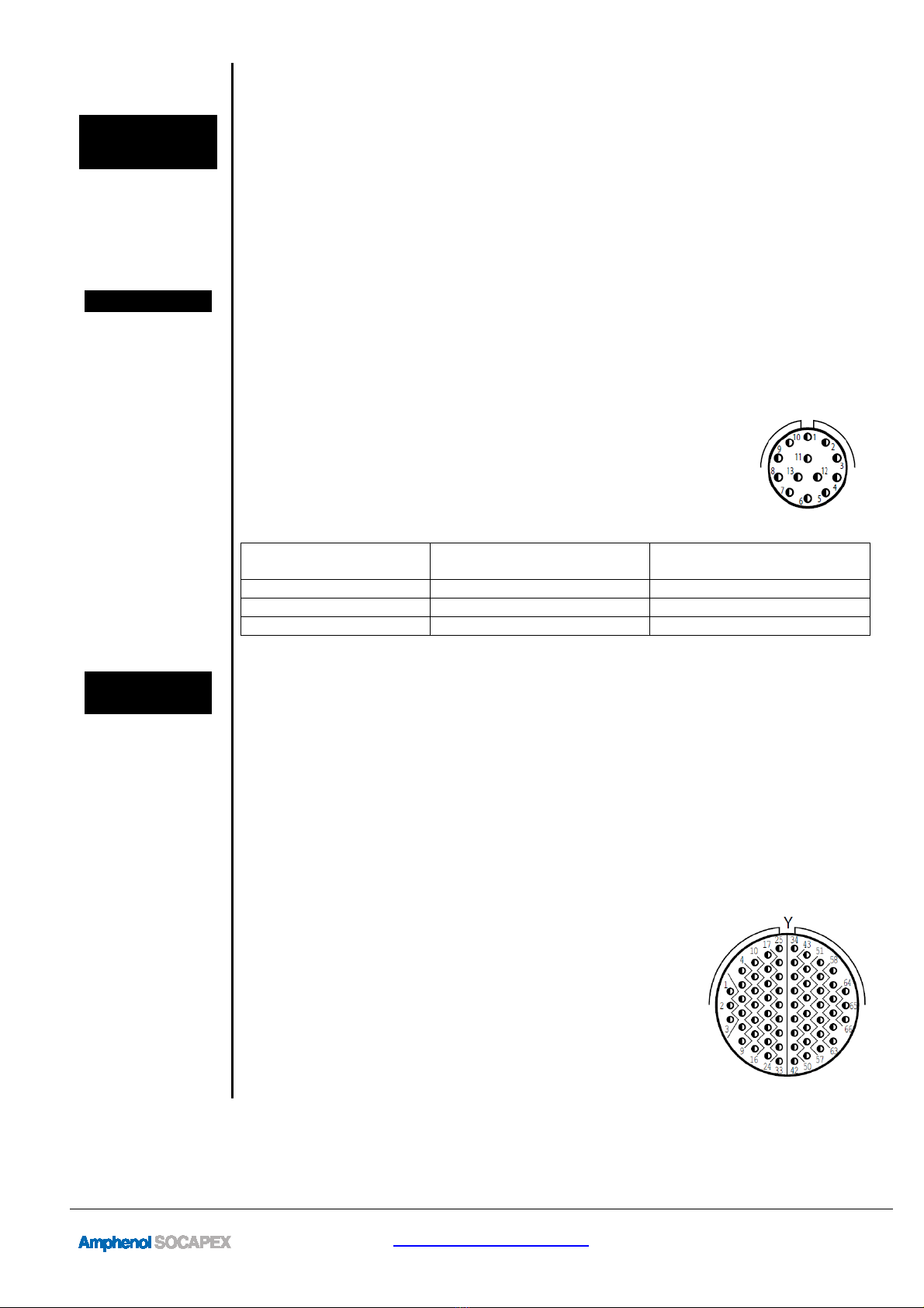
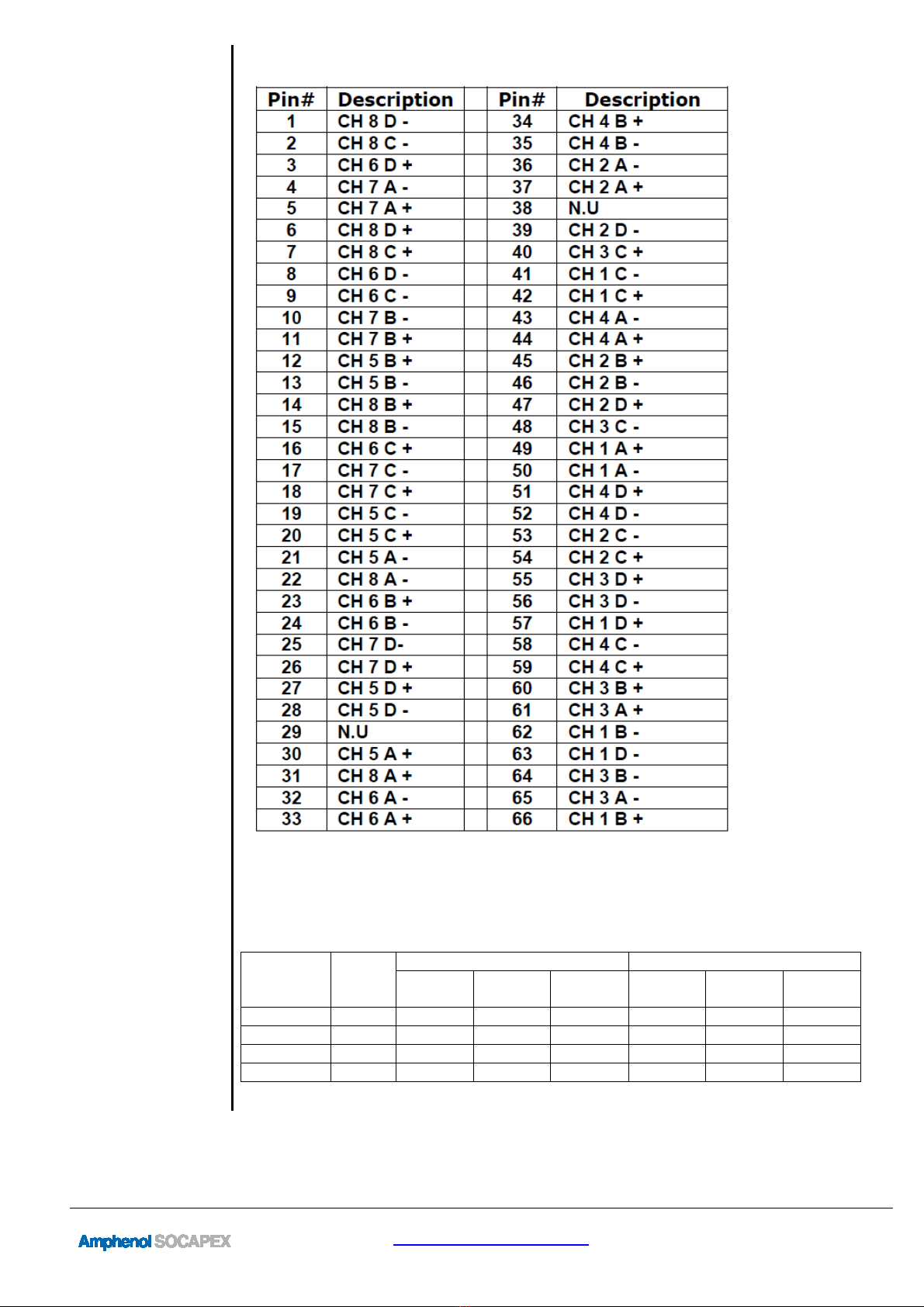
Ports
12x 10/100/1000BaseT(x) (Shielded RJ45)
All LAN ports shared into two MIL-DTL-38999 connectors
Voltage
24Vdc Nominal (16-36V)
Power consumption: 7W Typical
MIL standards
MIL-STD-1275, MIL-STD-704, MIL-STD-810F/G/GM, IP67
Electromagnetic
MIL-STD-461E Electromagnetic compatibility
CE-102, CS-114, CS-115, CS-116, RE-102, RS-103
Operating Temp.
-45ºC to +80ºC (-49ºF to +185ºF) – Cold Start-Up
Waterproof
IP67

RESMLAC
12E
MG
F35
-
UM
rev.
1
Page
4
/
16
www.amphenol-socapex.com
Tel: +33(0)4.50.89.28.00
Section 2 Hardware
Overview
The switches can be mounted directly to a flat surface or to a wall. Refer to the mechanical
drawing below. Its high protected enclosure makes it able to withstand immersion (IP67
rating).
The Ethernet connections come out from rugged MIL-STD-38999 connectors.
Front Panel
Display
The following describes the front panel, and LED indicators of the RESMLAC-12EMG-
F35.
LED Indicators
The RESMLAC-12EMG-F35 unit has LEDs indications,
•
1 LED - Power Indications
•
24 LEDs – Ethernet Indications.
The PWR LEDs is illuminated when input power is applied to the RESMLAC-12EMG-
F35.
Each of the 12 LAN ports has two LED with dual color indication, Yellow and green.
Table 5 – LED Indicators
Indicator
LED
Marking
Descriptio
n
General
Indications
Power
Statu
s
Green LED ON: PW
R OK
Ethernet
Indications
Speed
Port number
100
Mbps Green
1000
Mbps Yellow
L nk/Act v ty
Port number
Green ON
–
L nk s OK
Green Fla
sh ng
–
Transm tt ng
or Rece v ng Data
OFF
–
No l nk and No Da
ta

RESMLAC
12E
MG
F35
-
UM
rev.
1
Page
5
/
16
www.amphenol-socapex.com
Tel: +33(0)4.50.89.28.00
Section 3 Installation
Selecting a
Site
As with any electronic device, you should place the switch where it will not be subject to
extreme temperatures, humidity, or electromagnetic interference that exceeds the
RESMLAC-12EMG-F35 profile. Specifically, the site you select should meet the following
requirements:
•The ambient temperature should be between -45 to +80 degrees Celsius.
•Surrounding electrical devices should not exceed the electromagnetic field (RFC)
standards for MIL-STD-461E.
CAPS for
unused
connectors
The switches are pre-equipped with caps on all ports, including power and Ethernet.
Make sure all connectors are protected with cap or sealed plug to ensure sealing
and prevent from deterioration of the contacts.
Mounting
The RESMLAC-12EMG-F35 Ethernet Switch can be fastened to any flat surface by
mounting the box directly. Refer to the mechanical drawings below. Make sure to allow
enough room to route your Ethernet and power cables.
The RESMLAC-12EMG-F35 weighs 1.150 Kg and is mounted via its four # 10-32UNF
Captive Screws.
The overall external dimensions of the RESMLAC-12EMG-F35 are 178(L) x 136(W) x 47(H)
millimeters.

RESMLAC
12E
MG
F35
-
UM
rev.
1
Page
6
/
16
www.amphenol-socapex.com
Tel: +33(0)4.50.89.28.00

RESMLAC
12E
MG
F35
-
UM
rev.
1
Page
7
/
16
www.amphenol-socapex.com
Tel: +33(0)4.50.89.28.00
Section 4 Wiring
Overview
These switches provide connections to Ethernet devices in harsh environment. Typically,
a port is used to connect to another Ethernet switch that is connected to the main Ethernet
backbone. The other Ethernet ports are then connected to Ethernet devices such as
communication systems, Ethernet I/O, or industrial computers. Electrical isolation is
provided on the Ethernet ports for increased reliability.
Please follow normal Ethernet wiring practices when installing these switches.
Power wiring
Power is provided to the switch through J1. The switches should be powered using
mating plugs and backshells compliant with MIL-DTL-38999 series III. We suggest using
hereunder accessories. Another backshell can be used but it must ensure a correct sealing
protection.
Power plug
part number
Amphenol designation: TV06 RW 11 35 SN
This plug is size 11. It is coming with 13 contacts size 22D
(designed for 5A nominal current).
Power plug
wiring
Contact Signal Suggested Harness
Color Table
6 24 V (+) red
3 24 V (-) black
All other contacts Not connected None
Ethernet
wiring
These switches provide connections to Ethernet devices on the battlefield. Typically, a
port is used to connect to another Ethernet switch or hub that is connected to the main
Ethernet backbone. The other Ethernet ports are then connected to Ethernet devices such
as communication systems, Ethernet I/O, or industrial computers. Electrical isolation is
provided on the Ethernet ports for increased reliability.
Please follow normal Ethernet wiring practices when installing these switches.
The switches should be connected using mating plugs and backshells compliant with
MIL-DTL-38999 series III. We suggest using hereunder accessories. Another backshell
can be used but it must ensure a correct sealing protection.
Ethernet plug
part number
LAN ports are shared through J2 and J3.
J2 & J3 Amphenol designation: TV06RW1935SN (F35)
These plugs are size 19. They are coming with 66 contacts
size 22D.

RESMLAC
12E
MG
F35
-
UM
rev.
1
Page
8
/
16
www.amphenol-socapex.com
Tel: +33(0)4.50.89.28.00
Ethernet plug
wiring Pinout for J2 connector

RESMLAC
12E
MG
F35
-
UM
rev.
1
Page
9
/
16
www.amphenol-socapex.com
Tel: +33(0)4.50.89.28.00
Ethernet ports
connection
Pinout for J3 connector
The following table indicates the appropriate wiring connections for the Gigabit Ethernet
ports relative to the available link speeds. Please note that MDI is the preferred
connection choice. The Ethernet switches are capable of connecting using the MDIX
scheme, but it is not advised.
Switch
Contacts
RJ-45
Pinout
P/N
MDI MDI-X
1000
Base-T
100
Base-T
10 Base-
T
1000
Base-T
100
Base-T
10 Base-
T
Pair 0 (+/-) 1/2 BI_DA+- TX+- TX+- BI_DA+- RX+- RX+-
Pair 1 (+/-) 3/6 BI_DB+- RX+- RX+- BI_DB+- TX+- TX+-
Pair 2 (+/-) 4/5 BI_DC+- Unused Unused BI_DC+- Unused Unused
Pair 3 (+/-) 7/8 BI_DD+- Unused Unused BI_DD+- Unused Unused

RESMLAC
12E
MG
F35
-
UM
rev.
1
Page
10
/
16
www.amphenol-socapex.com
Tel: +33(0)4.50.89.28.00
Serial wiring
To manage the switch via the WEB interface you can use all tweve ports.
You can access the CLI mode via port MNG through serial link.
The following table indicates the appropriate wiring connections for the serial port, spread
among J2 connector.

RESMLAC
12E
MG
F35
-
UM
rev.
1
Page
11
/
16
www.amphenol-socapex.com
Tel: +33(0)4.50.89.28.00
Tooling
The plugs are using crimp contacts.
We suggest using hereunder tooling.
Crimping tools
Amp
henol No
Military No
Crimping tool 809 801 M22520/2-01
Positioner 809 835 M22520/2-07
Plastic insertion and
removal tools
Contact size Amphenol No Military no
22D 809 856 M81969/14-01
Backshell
We suggest using TV35 backshells with corresponding heat shrinks.
These band backshells provide a full 360° shield termination. They are available with
different cabling chamber lengths and exit diameters. The use of replaceable bands
facilitates future maintenance or reparability. Sealing is ensured by straight or right
angled heat shrink moulded piece at the rear of backshell.
TV35 is suitable for TV-CTV (MIL-DTL-38999 Series III). These straight band
backshells provide a full 360° shield termination with a quick, easy and cost effective
cabling process.
Heat-shrinks are molded pieces for harsh environment, fluid resistant (with
preinstalled adhesive).

RESMLAC
12E
MG
F35
-
UM
rev.
1
Page
12
/
16
www.amphenol-socapex.com
Tel: +33(0)4.50.89.28.00
Section 5 Management
Management
The switch is managed. It can be accessed either using the web interface or using RS-232
console port (shared among J2 connector, see Serial Wiring for details).
Web
management
For in-band Ethernet management configuration use either one of the 12 ports.
Configure your computer with compatible IP address and access to the switch using a web
browser.
Switch default IP address: 192.168.1.111
Mask: 255.255.255.0
Gateway: [empty].
Enter ‘admin’ for the password.
You have now access to the configuration settings. You can enter your desired IP address
and subnet, or enable DHCP.
Serial
management
The management port supports out-of-band configuration management of the switch.
There is one serial port associated with the Management Processor.
This port is RS-232 compatible and can operate only at:
• 115,200 baud rate
• 1 Stop Bits
• No Parity
• No Flow Control
Consult the dedicated Command Line Interface User Manual for getting all details
regarding the commands description.

RESMLAC
12E
MG
F35
-
UM
rev.
1
Page
13
/
16
www.amphenol-socapex.com
Tel: +33(0)4.50.89.28.00
Section 6 Features Overview
Switching
Features
Here’s a brief explanation of some of the features found in these switches documented by
this manual.
ETHERNET PORTS
•12 x switched 10/100/1000 (Gigabit Ethernet) ports
STANDARDS COMPLIANCE
•IEEE 802.1x MAC based Authentication
•IEEE 802.1Q VLAN Tagging
•IEEE 802.1P QoS
•IEEE 802.1S Multiple STP
•IEEE 802.1W Rapid STP
•IEEE 802.1AD Link Aggregation
•IEEE 802.1X
NETWORKING
•Spanning Tree (802.1d), RSTP (802.1w) and multiple Spanning Tree (802.1S) for
fast recovery rings
•Security via Radius Authentication 802.1x, Port Security, Port Mirroring
•Multicasting (IGMP Snooping), GARP, GMRP, and GVRP Broadcasting and
flooding Control up to 8K Groups.
•802.1q Tagged based VLAN up to 4K VLAN groups.
•QoS Multi-Layer Classifier, 802.1p, ToS/DSCP traffic classification. WFQ, Strict
Queuing.
•Bridge support for Q-in-Q.
•Link Aggregation 802.3AD.
•WEB, CLI, Telnet Management.
STANDARDS
•MIL-STD-1275
•MIL-STD-461E
•MIL-STD-704
•MIL-STD-810F GM
•IP67

RESMLAC
12E
MG
F35
-
UM
rev.
1
Page
14
/
16
www.amphenol-socapex.com
Tel: +33(0)4.50.89.28.00
PERFORMANCE
•26.8 Mpps wire speed forwarding rate
•20 Gbps maximum forwarding bandwidth
•8K MAC Address
CHASSIS
•Machined rugged aluminum
•Conductively cooled w/custom internal heat-sinks
•Ingress protection against sand, dust and moisture
•Anodize Coating, MIL-A-8625, Type II, Class 2
POWER
•Exceed MIL-STD-1275 Surge and Spike protection
•Voltage Input: 24Vdc Nominal (18-32V)
•Power Consumption: 7W Typical
•Ground: Grounding screw provided for connection to system chassis ground
ELECTROMAGNETIC
•MIL-STD-461E Electromagnetic compatibility
•CE-102, CS-114, CS-115, CS-116, RE-102, RS-103
SHOCK/VIBRATION/HUMIDITY
•MIL-STD-810G:
Random vibration (514.5I)
Bench Handling (516.6VI)
High Temp. (501.5I,II)
Low Temp. (502.5I)
Humidity (507.5II)
Air Pressure (500.5I,II)
Blowing Rain (506.5I)
Immersion (512.5I)
Salt Atmosphere (509.5I),
Blowing Dust (510.5I)
Loose Cargo Vibration (514.6II)
Wind Analysis.
•IP67
PHYSICAL
•Dimensions: 178 (L) x 136(W) x 47(H), including connectors & hardware
•Weight: 1.150kg

RESMLAC
12E
MG
F35
-
UM
rev.
1
Page
15
/
16
www.amphenol-socapex.com
Tel: +33(0)4.50.89.28.00
INSTALLATION
•Set of Four # 10-32UNF Captive Screws for mounting to any flat surface.
COOLING
•No Moving Parts. Passive Cooling
OPERATING TEMP
•-45ºC to +80ºC (-49ºF to +176ºF) – Cold Start-Up
STORAGE TEMP
•-45ºC to +85ºC (-49ºF to +185ºF)

RESMLAC
12E
MG
F35
-
UM
rev.
1
Page
16
/
16
www.amphenol-socapex.com
Tel: +33(0)4.50.89.28.00
Section 7 Service Information
Service
Information
We sincerely hope that you never experience a problem with any Amphenol product. If you
do need service, call Amphenol at +33(0) 450 89 28 00 and ask for Applications
Engineering. A trained specialist will help you to quickly determine the source of the
problem. Many problems are easily resolved with a single phone call. If it is necessary to
return a unit to us, an RMA (Return Material Authorization) number will be given to you.
Amphenol tracks the flow of returned material with our RMA system to ensure speedy
service. You must include this RMA number on the outside of the box so that your return
can be processed immediately.
The applications engineer you are speaking with will fill out an RMA request for you. If the
unit has a serial number, we will not need detailed financial information. Otherwise, be sure
to have your original purchase order number and date purchased available.
We suggest that you give us a repair purchase order number in case the repair is not covered
under our warranty. You will not be billed if the repair is covered under warranty.
Please supply us with as many details about the problem as you can. The information you
supply will be written on the RMA form and supplied to the repair department before your
unit arrives. This helps us to provide you with the best service, in the fastest manner.
Normally, repairs are completed in two days. Sometimes difficult problems take a little
longer to solve.
We apologize for any inconvenience that the need for repair may cause you. We hope that
our rapid service meets your needs. If you have any suggestions to help us improve our
service, please give us a call. We appreciate your ideas and will respond to them.
For Your Convenience:
Please fill in the following and keep this manual with your Amphenol system for future
reference:
P.O. #:__________________ Date Purchased: ___________________
Purchased From:______________________________________________
Product
Support
To obtain support for Amphenol products:
Visit our website. https://www.amphenol-socapex.com/en/technical-support
Phone: +33(0) 450 89 28 00
Mailing Address: Amphenol, Promenade de l’Arve, B.P.29, 74311 Thyez Cedex, France
For more
information
You will find all useful information on the RJ-Switch series on the dedicated website:
https://www.amphenol-socapex.com/en/products/connectors/rugged-ethernet-usb/ethernet-
mili
tary
-
switch
es
Other Amphenol Socapex Switch manuals