5
Amphenol Network Solutions
All rights reserved. 12.05.19 145121-2 A0
509.926.6000 – amphenol-ns.com
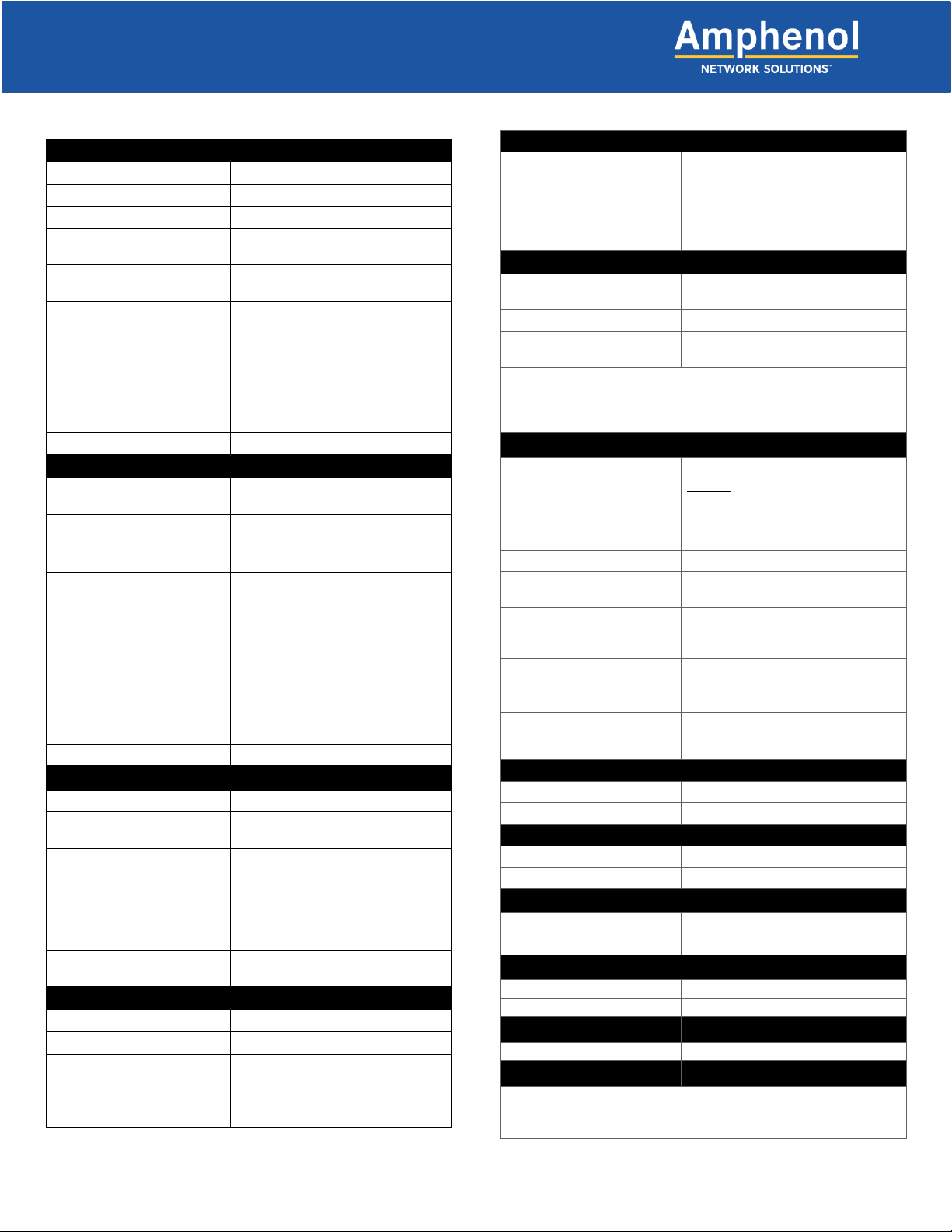
Specifications
Inputs
Voltage range, nominal voltage -40V to -60V (Nominal -48 VDC)
Max. input load rating 600A per side at max.
Short circuit withstand rating 5000A (breakers/fuses); 450A GMT
Nominal power loss at full load Less than 75W per side @ 28,000W
full load per side (600A x 48V)
Percentage of full power
dissipation at nominal voltage
Less than 1%
Max. input interrupt device 750A
Input terminal studs
(with nuts, flat washers and
spring washers) for dual-hole
compression lugs
• Two pair of 3/8 – 16 studs on 1
in. centers per terminal [max.
lug width of 1.94 in. (49.2 mm)]
per pair
• Torque nut (using 9/16 in. or 15 mm
wrench) to 150 in.-lb (~17 N•m),
max.
Input wire size #1 AWG to 750 MCM
Max. output single-pole, long-
delay circuit breaker (ea.)
100A
Max. output TPS or TLS 125A
Max. output load (ea.) -
continuous
100A
Minimum short circuit
interrupt rating
5000A
Output terminal studs (with
KEPS, nuts and washers)
for dual-hole compression
lugs
• 1/4 - 20 studs on 5/8 in. centers
[max. lug width of 0.680 in.
(15.8 mm) for a BATT terminal
and
0.70 in. (17.7 mm) for a RETURN
terminal].
• Torque bolts (using 7/16 in. or 12
mm wrench) to 50 in.-lb (~5.5
Output wire size #14 AWG minimum
GMT Outputs
Max. GMT output fuse (ea.) 20A
Max. GMT output load (ea.) -
continuous
14A
Minimum short circuit interrupt
rating
450A
GMT output terminals for
compression lugs
• 10 removable, #6-32 panhead
screws (max. lug width of 0.29 in.
[7.4 mm]).
• Torque to 6.3 in.lb (~0.7N•m), max.
GMT output wire size #22 AWG to #12 AWG, depending on
output fuse rating
Dry Contact Alarms
Alarm wire size #22 to #18 AWG
Alarm terminals Wire wrap
Relay contact ratings Dry Form-C contacts (1A @ 30 VDC,
0.5A @ 60 VDC, 0.3A @ 125 VAC)
Max. alarm power rating @24V: 72 mA (1.73W)
@48V: 147 mA (7.06W)
Grounding
Earth GND terminal bolts
(with washers) for dual-hole
compression lug
• Two pair of 1/4 - 20 threaded
holes on 5/8 in. centers.
• Torque bolts (using 7/16 in. or 12
mm wrench) to 50 in.-lb (5.5 N•m),
Ground wire size #2 AWG recommended
Voltage Sensor
Sensor accuracy 0 to -19.99V: ±0.3V
-20V to -60V: ±0.1V
Voltage measurement range 0 to -60 VDC
Feed voltage detection 0 to -19.99V: Alarm
-20V to -60V: Normal
NOTE:
• Voltage measurement may be slightly different than at input
terminal blocks due to the voltage drop within the panel.
• Sensors are factory calibrated and do not require user adjustment.
Communication
nrgNET sensor and alarm
card power
(via nrgNET cabling
connection to an
nrgCONTROL-BT controller)
-48 VDC nominal
*NOTE: The nrg600BT08-M chassis
MUST BE connected to an
nrgCONTROL-BT controller via
nrgNET cabling for LED Alarm
nrgNET data communication RS-485
nrgNET connector Removable 5-pin connector with
screw down terminals
nrgNET connector functions nrgNET IN from the nrgCONTROL or
nrgSMART Panel, nrgNET OUT to next
inline nrgSMART panel
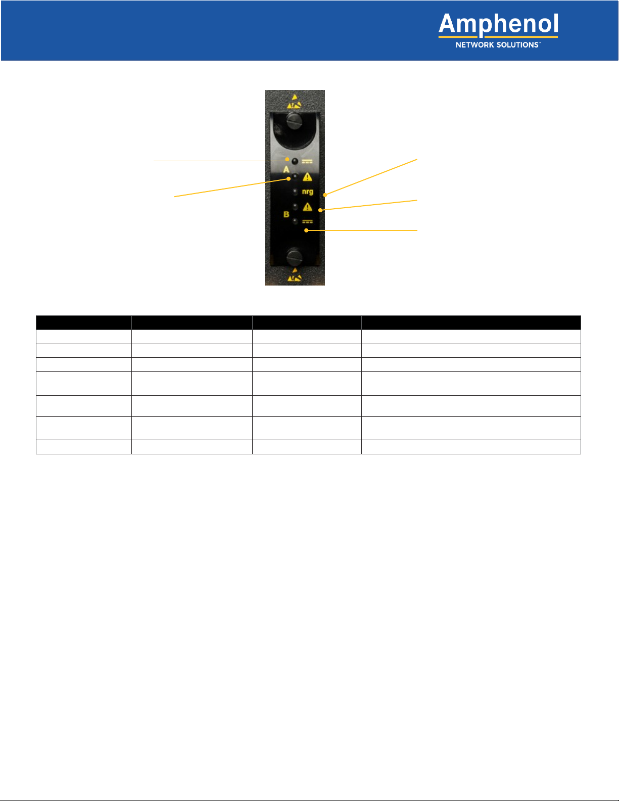
LED Alarm Indicators
(requires nrgNET & controller
for power)
A/B bus power
A/B fuse alarms
Supported protocols Proprietary nrgNET used to
communi- cate between panels and
Fit and Finish
Material 14-gauge steel
Color Pewter grey powder coat
Mechanical
Dimensions (L x W x H): 12” x 17.25” x 7”
Rack space 4RU
Environmental
Operating temperature -5° to +44°C
Humidity 0 to 90%, non-condensing
Weight (approximate)
Compliance
Warranty
Standard 1-year warranty on all parts.
The warranty is extended through the addition of the annual
maintenance and support contract (nrgSMART-APSC)