manuals.online logo
Brands
  1. Home
  2. •
  3. Brands
  4. •
  5. CHINT
  6. •
  7. Circuit Breaker
  8. •
  9. CHINT NA8G User manual

CHINT NA8G User manual

Air Circuit Breaker
Leading every step, reliable new height
Air Circuit Breaker
Leading every step, reliable new height
Page P-001 Page P-039
ACB
Air Circuit Breaker
NA8G
NA1
Page P-001 Page P-039
ACB
Air Circuit Breaker
NA8G
NA1
Air Circuit Breaker
3. Product structure
Secondary connecting part
Shunt release
Intelligent controller
Energy storage & release indicator
Operating mechanism
Closing electromagnet
Energy storage handle
Making button
Motor-driven energy storage mechanism
Breaking button
Breaking/making indicator
Under voltage release
Zero arcover hood
Name plate
Energy storage handle
Secondary connecting part
Making button
Energy storage & release indicator
Fault-breaking indicator reset button
Breaking button
Breaking/Making indicator
Intelligent controller
NA8G Air Circuit Breaker P-002
Body structure
No. of poles:
3:3-pole
4:4-pole
Rated current:
Mode of installation:
F:Fixed type
D:Draweout type
Mode of operation:
M:Manual
P: Power-driven
2.6 Type designation
NA8 G - □-□□ / □-□-□-□-□
Voltage of secondary circuit
AC230V, AC400V
DC220V, DC110V
Wiring of main circuit:
H:Horizontal wiring of main circuit
V:Vertical wiring of main circuit
Intelligent controller:
M: Standard type
H: Multifunctional type
Frame size
rated current
3200A
6300A
1600A
Frame size rated current:
1600A, 3200A, 4000A 6300A,
Design sequence number
ACB
Company code
Improved product code
Rated current
1600A
2000A
2500A
3200A
4000A
5000A
6300A
400A
630A
800A
1000A
1250A
1600A
4000A
2500A
3200A
4000A
1. General
NA8G Air Circuit Breaker
2. Operating conditions
1.1 Application scope
With rated current from 200A to 6300A, and rated service
voltage of AC 415V or 690V, NA8G series air circuit breaker is
mainly used in the distribution network with the circuit of AC
50HZ/60HZ to distribute electric energy and protect circuits
and electric equipment against over-load, under-voltage,
short- circuit, single-phase earthing fault.
Having art-oriented appearance, high breaking capacity, zero
arcover and varities of intellectualized protection functions, the
breaker can be used for selective protection with accurate
action, no unnecessary power cut, and better power supply
reliability.
That breaker can be widely used for power stations, factories,
mines and modern tall buildings, especially the distribution
system in the intelligent building, and also widely used in
green projects such as wind and solar power generation.
1.2 Standard : IEC/EN 60947-2.
2.1 Temperature condition:
-5℃~40℃; the average value within 24h shall not exceed
+35℃ (special situation excluded);
2.2 Altitude:≤2000m;
2.3 Pollution grade: Grade 3;
2.4 Air conditions:
At mounting site, relative humidity not exceed 50% at the max
temperature of +40℃, higher relative humidity is allowable
under lower temperature, RH could be 90% at +20℃, special
measures should be taken to occurrence of dews;
2.5 Note: Without the intelligent controller,
the breaker functions as a switch-disconnector.
NA8G
P-001
Drawout structure
Secondary connecting part
Safety separator
Extraction draw plate
Rocking handle work hole
Position indicator
Locking device
Rocking handle deposit hole
Guide rail
Baffle push rod
Side panel
Test
Connected
Disconnected
Test
Connected
Disconnected
Test
Connected
Disconnected
Connected: both main circuit and secondary circuit are connected Test: the main circuit is disconnected,
the safety separator works well,
and the secondary circuit is connected.
Disconnected: neither main circuit nor secondary circuit is connected
Press Press
Energy
storag e
Breaker off and energy storage over Breaker off and no energy storage
Press
Press
Energy
releas e
Breaker on and energy storage over Breaker on and no energy storage
Pres sPres s
Energy
storage
Pres s
Pres s
Energy
releas e
(5)Push the breaker body in, and turn the break body to the connected position
(3)Place the breaker body on the guide rail (4)Move the breaker body onto the guide rail with a snap
(2)Pull out the guide rail(1)Draw-out socket placed horizontally
Air Circuit Breaker NA8G Air Circuit Breaker P-004
NA8G
P-003
1600
3200
6300
Style wiring
mode ambient
temperature℃
Draw-out type
Front/rear horizontal wiring mode
Altitude(m)
Insulation withstand voltage(V)
Insulation voltage(V)
Rated operational voltage(V)
Rated operational current(A)
2000
3500
1000
690
1×In
3000
3000
800
580
0.96×In
5000
2000
600
400
0.87×In
45
400
630
800
1000
1250
1550
1600
2000
2500
3200
4000
5000
6100
50
400
630
800
1000
1250
1500
1600
2000
2500
3100
4000
4700
6000
Rear vertical wiring mode
-5~40
400
630
800
1000
1250
1600
1600
2000
2500
3200
4000
5000
6300
4000
2500
700
500
0.92×In -
4000
2500
3100
3600
55
400
630
800
950
1150
1450
1600
2000
2450
3000
3900
4600
5500
2450
3000
3400
60
400
550
700
900
1050
1350
1600
1900
2350
2900
3800
4400
5200
2350
2900
3200
45
400
630
800
1000
1250
1600
1600
2000
2500
3200
4000
5000
6100
2500
3200
3800
50
400
630
800
1000
1250
1550
1600
2000
2500
3200
4000
4800
6000
2500
3200
3600
55
400
630
800
950
1200
1500
1600
2000
2500
3050
3900
4650
5500
2500
3050
3400
60
400
580
700
900
1100
1450
1600
1950
2400
2900
3800
4500
5200
2400
2900
3200
-5~40
400
630
800
1000
1250
1600
1600
2000
2500
3200
4000
5000
6300
2500
3200
4000
2500
3200
4000
2500
3200
3800
Air Circuit Breaker NA8G Air Circuit Breaker P-006
NA8G
P-005
In(A)
Thickness(mm)
Width(mm)
Number of buses
Busbar
400
5
50
1
630
5
40
2
800
5
50
2
1000
5
60
2
1250
8
60
2
1600
10
60
2
1600
6
100
2
2000
6
100
3
2500
5
100
4
3200
10
100
4
250
6
80
4
3200
10
100
4
4000
10
100
5
4000
10
100
5
5000
10
100
7
6300
10
100
8
Inm(A) NA8G-1600 NA8G-3200 NA8G-6300NA8G-4000
NA8G-1600
NA8G-3200
NA8G-6300
400
630
800
1000
1250
1600
1600
2000
2500
3200
4000
5000
6300
140
161
215
230
250
460
390
470
600
670
550
590
950
80
100
110
120
130
220
170
250
260
420
-
-
2500
3200
4000
600
670
1047
260
420
656
NA8G-4000
-
Power loss
Breaker type Rated current Draw-out type Fixed type
Number of operations
Net weight (3 poles/4 poles)
Size(3 poles/4 poles)
Height × width × depth
Flashover distance mm
Wire incoming pattern
Shell grade rated current Inm (A)
Rated current In (A)
Nominal insulation voltage Ui (V)
Rated operational voltage Ue (V)
Rated ultimate short circuit breaking capacity Icu (kA)
Rated service short circuit breaking capacity Ics (kA)
Rated short time withstand current Icw, 1s (kA)
Frequency of operation (number of times/hour)
Mechanical life
Electrical Life
fixed type (kg)
draw-out type (kg)
fixed type
draw-out type
3000
1000
0
Wire to enter from the
upper or lower port
22/26.5
42.5/55
320×(254/324)×258
351×(282/352)×352
1600
400,630,800,
1000,1250,1600
690
415 690
50 25
40 20
40 20
20
52.5/66.5
98/121
3000
1000
0
Wire to enter from the
upper or lower port
406×(422/537)×329
439.5×(435/550)×445
3200
1600,2000,
2500,3200
1000
415 690
100 65
80 65
80 65
10
2000
500
0
Wire to enter from the
upper or lower port
-
210/233
-
439×(813/928)×501
6300
4000,5000 6300
1000
415
120
100
100
10
233
439×928×501
Number of poles 3P 4P 3P 4P 3P 4P
3P
4000
2500,3200,4000
1000
415 690
100 65
100 65
85 65
58/75
110/145
3000
1000
402×(432.5/547.5)×330
439.5×(435/550)×445
10
0
3P 4P
Wire to enter from the
upper or lower port
4. Main technical parameters
4.1 Main technical parameters
4.2 Capacity-reducing usage
4.2.1 Capacity-reducing at different temperatures
The following table shows the continual current-loading capacity of the circuit breakers and buses in each wiring mode at the
corresponding ambient environment temperatures and under the conditions of the satisfaction of conventional heating with a
similarity in capacity reducing between the breaker connected in a mixed way and the breaker connected horizontally.
4.2.2 Capacity-reducing at different altitudes
When the altitude is higher than 2000m, there will appear changes in insulation property, cooling performance, pressure,and the
performance can be modified in reference to the following table.
4.3 Power loss
Power loss is the loss at each pole which is measured when the breaker is charged with the rated current.
Note: The data and parameters in the above technical documentation results from tests and theoretical calculation,
and can only be used as a general type selection guide.They cannot replace industrial practical experience or proof test.
5.4 Recommended bus for the breaker and recommendation for users to install the buses
1600
3200
6300
Style wiring
mode ambient
temperature℃
Draw-out type
Front/rear horizontal wiring mode
Altitude(m)
Insulation withstand voltage(V)
Insulation voltage(V)
Rated operational voltage(V)
Rated operational current(A)
2000
3500
1000
690
1×In
3000
3000
800
580
0.96×In
5000
2000
600
400
0.87×In
45
400
630
800
1000
1250
1550
1600
2000
2500
3200
4000
5000
6100
50
400
630
800
1000
1250
1500
1600
2000
2500
3100
4000
4700
6000
Rear vertical wiring mode
-5~40
400
630
800
1000
1250
1600
1600
2000
2500
3200
4000
5000
6300
4000
2500
700
500
0.92×In -
4000
2500
3100
3600
55
400
630
800
950
1150
1450
1600
2000
2450
3000
3900
4600
5500
2450
3000
3400
60
400
550
700
900
1050
1350
1600
1900
2350
2900
3800
4400
5200
2350
2900
3200
45
400
630
800
1000
1250
1600
1600
2000
2500
3200
4000
5000
6100
2500
3200
3800
50
400
630
800
1000
1250
1550
1600
2000
2500
3200
4000
4800
6000
2500
3200
3600
55
400
630
800
950
1200
1500
1600
2000
2500
3050
3900
4650
5500
2500
3050
3400
60
400
580
700
900
1100
1450
1600
1950
2400
2900
3800
4500
5200
2400
2900
3200
-5~40
400
630
800
1000
1250
1600
1600
2000
2500
3200
4000
5000
6300
2500
3200
4000
2500
3200
4000
2500
3200
3800
Air Circuit Breaker NA8G Air Circuit Breaker P-006
NA8G
P-005
In(A)
Thickness(mm)
Width(mm)
Number of buses
Busbar
400
5
50
1
630
5
40
2
800
5
50
2
1000
5
60
2
1250
8
60
2
1600
10
60
2
1600
6
100
2
2000
6
100
3
2500
5
100
4
3200
10
100
4
250
6
80
4
3200
10
100
4
4000
10
100
5
4000
10
100
5
5000
10
100
7
6300
10
100
8
Inm(A) NA8G-1600 NA8G-3200 NA8G-6300NA8G-4000
NA8G-1600
NA8G-3200
NA8G-6300
400
630
800
1000
1250
1600
1600
2000
2500
3200
4000
5000
6300
140
161
215
230
250
460
390
470
600
670
550
590
950
80
100
110
120
130
220
170
250
260
420
-
-
2500
3200
4000
600
670
1047
260
420
656
NA8G-4000
-
Power loss
Breaker type Rated current Draw-out type Fixed type
Number of operations
Net weight (3 poles/4 poles)
Size(3 poles/4 poles)
Height × width × depth
Flashover distance mm
Wire incoming pattern
Shell grade rated current Inm (A)
Rated current In (A)
Nominal insulation voltage Ui (V)
Rated operational voltage Ue (V)
Rated ultimate short circuit breaking capacity Icu (kA)
Rated service short circuit breaking capacity Ics (kA)
Rated short time withstand current Icw, 1s (kA)
Frequency of operation (number of times/hour)
Mechanical life
Electrical Life
fixed type (kg)
draw-out type (kg)
fixed type
draw-out type
3000
1000
0
Wire to enter from the
upper or lower port
22/26.5
42.5/55
320×(254/324)×258
351×(282/352)×352
1600
400,630,800,
1000,1250,1600
690
415 690
50 25
40 20
40 20
20
52.5/66.5
98/121
3000
1000
0
Wire to enter from the
upper or lower port
406×(422/537)×329
439.5×(435/550)×445
3200
1600,2000,
2500,3200
1000
415 690
100 65
80 65
80 65
10
2000
500
0
Wire to enter from the
upper or lower port
-
210/233
-
439×(813/928)×501
6300
4000,5000 6300
1000
415
120
100
100
10
233
439×928×501
Number of poles 3P 4P 3P 4P 3P 4P
3P
4000
2500,3200,4000
1000
415 690
100 65
100 65
85 65
58/75
110/145
3000
1000
402×(432.5/547.5)×330
439.5×(435/550)×445
10
0
3P 4P
Wire to enter from the
upper or lower port
4. Main technical parameters
4.1 Main technical parameters
4.2 Capacity-reducing usage
4.2.1 Capacity-reducing at different temperatures
The following table shows the continual current-loading capacity of the circuit breakers and buses in each wiring mode at the
corresponding ambient environment temperatures and under the conditions of the satisfaction of conventional heating with a
similarity in capacity reducing between the breaker connected in a mixed way and the breaker connected horizontally.
4.2.2 Capacity-reducing at different altitudes
When the altitude is higher than 2000m, there will appear changes in insulation property, cooling performance, pressure,and the
performance can be modified in reference to the following table.
4.3 Power loss
Power loss is the loss at each pole which is measured when the breaker is charged with the rated current.
Note: The data and parameters in the above technical documentation results from tests and theoretical calculation,
and can only be used as a general type selection guide.They cannot replace industrial practical experience or proof test.
5.4 Recommended bus for the breaker and recommendation for users to install the buses
NA8G-1600 (In=1600A) Draw-out type
(Only horizontal connection is provided by the factory, vertical one has to be made by users themselves).
NA8G-1600 (In=400A ~1250A) Draw-out type
(Only horizontal connection is provided by the factory, vertical one has to be made by users themselves).
5. Dimensions and connection
Note: If users intend to change the
horizontal connection into vertical
connection, they need to replace the
upper and lower busbars on both sides
with the same one as the central busbar.
In(A)
400, 630
800, 1000
1250
a(mm)
5
10
15
Vertical connection
351
282(3P)
352(4P)
149(3P)
155(4P)
78.5(3P)
75.5(4P)
345(Connected position)
391(Disconnected position)
95 76
7
Phases barrier
(to be ordered
separately)
345(Connected position)
391(Disconnected position)
Horizontal connection
95 76
310
149
7
a
78.5
2-Φ6.5×10
2-Φ6.5
145(3P)
215(4P)
95
210
36
275
63
35
76 76 76
12×Φ11(3P)
16×Φ11(4P)
35
60
25
15
N Pole
3P Central line
4P Central line
351
282(3P)
352(4P)
442(Connected position)
488(Disconnected position)
95 76
149(3P)
155(4P)
78.5(3P)
75.5(4P)
7
442(Connected position)
488(Disconnected position)
95 76
179
15
7
63.5
2-Φ6.5×10
2-Φ6.5
145(3P)
215(4P)
95
210 36
63
35
310
275
24×Φ11(3P)
32×Φ11(4P)
101 101 101
85
35
80.5
35
15
N pole
3P Central line
4P Central line
Phases barries
(to be ordered separately)
Phases barrier
(to be ordered separately)
Horizontal connection
Vertical connection Note: If users intend to change the
horizontal connection into vertical
connection, they need to replace the
upper and lower busbars on both sides
with the same one as the central busbar.
NA8G-1600 (400A~1250A) Fixed type
(Only horizontal connection is provided by the factory, vertical one to has be made by users themselves).
NA8G-1600 (In=1600A) Fixed type
(Only horizontal connection is provided by the factory, vertical one has to be made by users themselves).
Note: If users intend to change the
horizontal connection into vertical
connection, they need to replace the
upper and lower busbars on both sides
with the same one as the central busbar.
In(A)
400, 630
800, 1000
1250
a(mm)
5
10
15
149 48.5
100 92
251
a
237(3P)
307(4P)
320
76 76 76
35
60
25
15
4-Φ7
237(3P)
307(4P)
100
254(3P)
324(4P)
149(3P)
155(4P)
100 92
251
48.5(3P)
45.5(4P)
210
22
275
281
Phases barrier
(to be ordered
separately)
Horizontal connection
Phases barrier
(to be ordered
separately)
Vertical connection
N Pole
12×Φ11(3P)
16×Φ11(4P)
4P Central line
3P Central line
7
7
C
C
Note: If users intend to change the
horizontal connection into vertical
connection, they need to replace the
upper and lower busbars on both sides
with the same one as the central busbar.
320
100 92
341
100 92
341
4-Φ7
237(3P)
307(4P)
100
15
237(3P)
307(4P)
254(3P)
324(4P)
149(3P)
155(4P)
48.5(3P)
45.5(4P)
179
33.5
275
281
24-Φ11(3P)
32-Φ11(4P)
101 101
80.5
85
35
35
15
101
3P Central line
4P Central line
210
22
Separator between phases
(to be ordered separately)
Horizontal connection
Vertical connection
Phases barrier
(to be ordered
separately)
N Pole
7
7
C
C
Air Circuit Breaker NA8G Air Circuit Breaker P-008
NA8G
P-007
NA8G-1600 Draw-out type
Size of the hole to be drilled on the panel
NA8G-3200 Draw-out type
Size of the hole to be drilled on the panel
8-Φ5
220
258
118.5
285
322
From the center of the mounting hole on the right side of the breaker
Breaker mounting panel
NA8G-3200 Draw-out type; Front connection
Note: If users want to change the horizontal connection into vertical connection, they only have to turn the busbar by 90°.
NA8G-1600 Fixed type
Size of the hole to be drilled on the panel
NA8G-3200(In=1600A~2500A) Draw-out type
(Only horizontal connection is provided by the factory).
NA8G-3200(In=1600A~2500A) Draw-out type
(Vertical connection has to be made by users themselves).
115 115 115
25 12-Φ13
86
C
2930129
15
In(A) C
1600, 2000, 2500 20
3200 30
16.5
Datum line
2584 112
Φ11
115
78
14
50
115 115
Datum line
29
52
445(Connected position)
492(Disconnceted position)
7
115 115 115
25
Φ11
14
7855
25
57.5
52
445(Connected position)
492(Disconnected position)
Datum line
7
Note: If users want to change the vertical connection into horizontal connection, they only have to turn the busbar by 90°.
C
C
C
C
C C
162.5(3P)
277.5(4P)
240199.5
217.5(3P)
332.5(4P)
Datum line 1
217.5
385
328
155145
268
18
47
10×Φ6
376
17597
371
162.5
Datum line
11×17
Φ14
21.5
52
Size of the hole to be drilled on the panel
Datum line 2
Datum line 2
10
Datum line 1
386 7
308
258
Installation panel
10-Φ5
220
258
78
320
118120118
2
Breaker mounting panel
From the center of the mounting hole on the right side of the breaker
Air Circuit Breaker NA8G Air Circuit Breaker P-010
NA8G
P-009
NA8G-3200(In= 3200A) Draw-out type (Only )horizontal connection is provided by the factory
NA8G-3200(In= 3200A) Draw-out type (Vertical connection has to be made by users themselves)
NA8G-3200 Fixed type
Note: If users want to change the horizontal connection into vertical connection,
it is necessary to replace the upper and lower busbars for the N and B phases with the same one as the A and C phases.
N
163.5
11
200(3P )
315(4P )
13
200 11 246 44 7
402
Datum line 1
Datum line 2
2590 112
100
126
14
25
Φ11
126 126
29
52
445(Connected position)
492(Disconnected position)
Datum line
7
115 115 115
25
Φ11
14
25
35.5
52
10057
445(Connected position)
492(Disconnected position)
Datum line
7
C
C
C
C
308
258
Air Circuit Breaker NA8G Air Circuit Breaker P-012
NA8G
P-011
NA8G-3200 Fixed type (Vertical connection has to be made by users themselves)
In(A)
1600~2500
3200
a(mm)
20
30
NA8G-3200 Fixed type, size of the hole to be drilled on the panel
NA8G-3200 Fixed type (Only )horizontal connection is provided by the factory
In(A)
1600~2500
3200
a(mm)
20
30
Note: If users want to change the horizontal connection into vertical connection, they only have to additionally install vertical busbars.
150
72.5
200(3P)
315(4P)
200
268
311
371
328
8×Φ6
4×Φ12
Datum line Datum line
12-Φ13
115
86
18.5
50
115 115
55
112 a
32
Ferrous material
Datum line
115 115 115
a
100
29
Φ11
57
25
55
32
45
14
Ferrous material
Datum line
Note: If users want to change the horizontal connection into vertical connection, they only have to additionally install vertical busbars.
C
C
C
C
21.5
29.5
Installation
panel
115 115 115
25 Φ11
78
C
2930129
15
16.5
CC
2584 133
100
126
14
25
Φ11
126 126
29
42
445(Connected position)
492(Disconnected position)
C
C
115 115 115
25
Φ11
14
25
35.5
42
445(Connected position)
492(Disconnected position)
10057
C
C
2584 133
Φ11
115
78
14
50
115 115
29
42
445(Connected position)
492(Disconnected position)
C
C
115 115 115
25
Φ11
14
7855
25
57.5
42
445(Connected position)
492(Disconnected position)
C
C
232199.5
217.5(3P)
332.5(4P)
217.5
385 1842
N
258
308
17597
162.5
162.5(3P)
277.5(4P)
11×17
φ11
φ14
11×17
φ14
10
328
155145
268
18
47
10×Φ6
376
371
21.5
NA8G-4000 Draw-out type, size of the hole to be drilled on the panel
datu m li ne 1
datum line 2
datu m li ne 1
datum line 2
datu m li ne 1
Size of the hole to be drilled on the panel
NA8G-4000(In=2500A) Draw-out type (only horizontal connection is provided by the factory)
NA8G-4000(In=2500A) Draw-out type (vertical connection has to be made by users themselves)
datu m li ne 1
Note: If users want to change the horizontal connection into vertical connection,they only have to rotate the busbars by 90°.
datu m li ne 1
Note: If users want to change the horizontal connection into vertical connection,they only have to rotate the busbars by 90°.
datu m li ne 1
datu m li ne 1
datu m li ne 1
NA8G-4000 Draw-out type, size of the hole to be drilled on the panel
NA8G-4000(In=3200A~4000A) Draw-out type (only horizontal connection is provided by the factory)
NA8G-4000(In=3200A~4000A) Draw-out type (vertical connection has to be made by users themselves)
Note: If users want to change the horizontal connection into vertical connection,they only have to change the busbar of N、B phases to A、C phases.
Air Circuit Breaker NA8G Air Circuit Breaker P-014
NA8G
P-013
In(A)
2500
3200~4000
C
25
30
115 115 115
25 Φ11
78
C
2930129
15
16.5
CC
2584 133
100
126
14
25
Φ11
126 126
29
42
445(Connected position)
492(Disconnected position)
C
C
115 115 115
25
Φ11
14
25
35.5
42
445(Connected position)
492(Disconnected position)
10057
C
C
2584 133
Φ11
115
78
14
50
115 115
29
42
445(Connected position)
492(Disconnected position)
C
C
115 115 115
25
Φ11
14
7855
25
57.5
42
445(Connected position)
492(Disconnected position)
C
C
232199.5
217.5(3P)
332.5(4P)
217.5
385 1842
N
258
308
17597
162.5
162.5(3P)
277.5(4P)
11×17
φ11
φ14
11×17
φ14
10
328
155145
268
18
47
10×Φ6
376
371
21.5
NA8G-4000 Draw-out type, size of the hole to be drilled on the panel
datu m li ne 1
datum line 2
datu m li ne 1
datum line 2
datu m li ne 1
Size of the hole to be drilled on the panel
NA8G-4000(In=2500A) Draw-out type (only horizontal connection is provided by the factory)
NA8G-4000(In=2500A) Draw-out type (vertical connection has to be made by users themselves)
datu m li ne 1
Note: If users want to change the horizontal connection into vertical connection,they only have to rotate the busbars by 90°.
datu m li ne 1
Note: If users want to change the horizontal connection into vertical connection,they only have to rotate the busbars by 90°.
datu m li ne 1
datu m li ne 1
datu m li ne 1
NA8G-4000 Draw-out type, size of the hole to be drilled on the panel
NA8G-4000(In=3200A~4000A) Draw-out type (only horizontal connection is provided by the factory)
NA8G-4000(In=3200A~4000A) Draw-out type (vertical connection has to be made by users themselves)
Note: If users want to change the horizontal connection into vertical connection,they only have to change the busbar of N、B phases to A、C phases.
Air Circuit Breaker NA8G Air Circuit Breaker P-014
NA8G
P-013
In(A)
2500
3200~4000
C
25
30
268
311
371
328
8×Φ6
21.5
29.5
432.5(3P)
547.5(4P)
400(3P)
515(4P)
330
78 150
4×Φ14
φ11
115
78
14
50
115 115
29
C
133
25
25
47.5
33
C
115 115 115
25 C
21
25
78
55
33
C
10.5
11 200(3P)
315(4P) 44
133
25
246 7
25
200 11
13
163.5 238.5
330
C
NA8G-4000 Fixed type , outline dimension
NA8G-4000 Fixed type ,size of the hole to be drilled on the panel
NA8G-4000(In=2500A) Fixed type (only horizontal connection is provided by the factory)
NA8G-4000(In=2500A) Fixed type (vertical connection has to be made by users themselves)
Note: If users want to change the horizontal connection into vertical connection,they only have to rotate the busbars by 90°.
datum line 1
datum line 2
datum line 1
datum line 1
datum line 1
115 115 115
25 φ11
78
15
C
388
15
10
61
155
15
67.5
15
155
C
100
126
14
25
Φ11
126 126
29
C
33
25
133
47.5
25
C
115 115 115
25 C
49
25
57
100
14
33
Φ11
C
NA8G-4000 Fixed type , outline dimension(Front connection)
NA8G-4000(In=3200A~4000A) Fixed type (only horizontal connection is provided by the factory)
NA8G-4000(In=3200A~4000A) Fixed type (vertical connection has to be made by users themselves)
Note: If users want to change the horizontal connection into vertical connection,they only have to change the busbar of N、B phases to A、C phases.
datum line 1
datum line 1
datum line 1
Air Circuit Breaker NA8G Air Circuit Breaker P-016
NA8G
P-015

This manual suits for next models

10

Other CHINT Circuit Breaker manuals

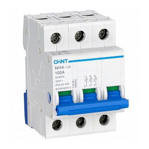
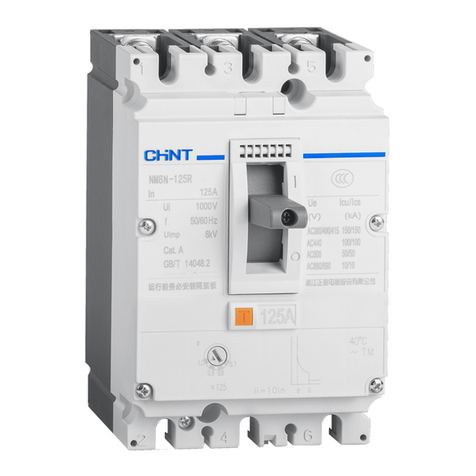
CHINT NH4-125 User manual

CHINT

CHINT NH4-125 User manual

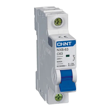
CHINT NXB-63 Installation instructions

CHINT

CHINT NXB-63 Installation instructions

CHINT NB2-40ZT Installation instructions

CHINT

CHINT NB2-40ZT Installation instructions

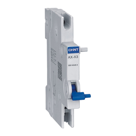
CHINT AX-5 User manual

CHINT

CHINT AX-5 User manual

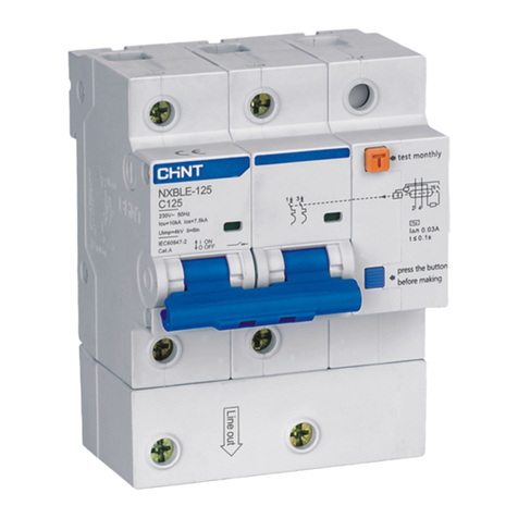
CHINT NXBLE-125 User manual

CHINT

CHINT NXBLE-125 User manual

CHINT NB2LE-40ZT Installation instructions

CHINT

CHINT NB2LE-40ZT Installation instructions

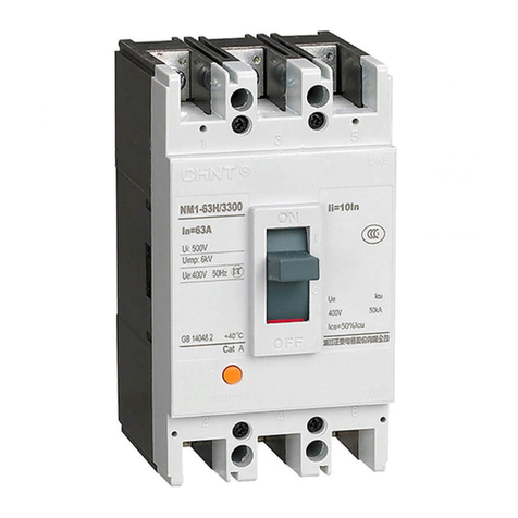
CHINT NM1 Series Installation instructions

CHINT

CHINT NM1 Series Installation instructions

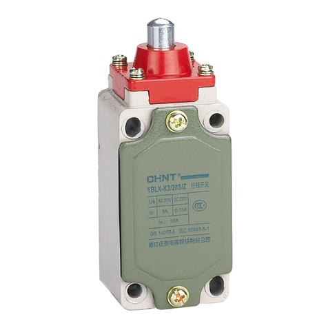
CHINT YBLX-K3 User manual

CHINT

CHINT YBLX-K3 User manual

CHINT NM8N Series User manual

CHINT

CHINT NM8N Series User manual

CHINT NB2-80ZT Installation instructions

CHINT

CHINT NB2-80ZT Installation instructions

CHINT AX-5 User manual

CHINT

CHINT AX-5 User manual

CHINT RT28 User manual

CHINT

CHINT RT28 User manual

CHINT NB1-63H/2 Installation instructions

CHINT

CHINT NB1-63H/2 Installation instructions

CHINT NB2LE-80ZT Installation instructions

CHINT

CHINT NB2LE-80ZT Installation instructions

CHINT NB1-63 Series Installation instructions

CHINT

CHINT NB1-63 Series Installation instructions

CHINT NH2-125 User manual

CHINT

CHINT NH2-125 User manual

CHINT AL-X1 User manual

CHINT

CHINT AL-X1 User manual

CHINT NXM Series User manual

CHINT

CHINT NXM Series User manual

CHINT OUVT-1 User manual

CHINT

CHINT OUVT-1 User manual

CHINT NA1-1000 Installer manual

CHINT

CHINT NA1-1000 Installer manual

CHINT NB1-63 Series Installation instructions

CHINT

CHINT NB1-63 Series Installation instructions

CHINT NB7 User manual

CHINT

CHINT NB7 User manual

CHINT NRE8 Series Installation instructions

CHINT

CHINT NRE8 Series Installation instructions

CHINT NXB-63G Series Installation instructions

CHINT

CHINT NXB-63G Series Installation instructions

Popular Circuit Breaker manuals by other brands

Siemens SIRIUS operating instructions

Siemens

Siemens SIRIUS operating instructions

Siemens 3VT3 Series operating instructions

Siemens

Siemens 3VT3 Series operating instructions

Siemens MTRPB installation instructions

Siemens

Siemens MTRPB installation instructions

Reliance electric FEDERAL PACIFIC DST-2 instruction manual

Reliance electric

Reliance electric FEDERAL PACIFIC DST-2 instruction manual

ABB 5VHK 250 Installation & maintenance instructions

ABB

ABB 5VHK 250 Installation & maintenance instructions

Delixi NAVIGATOR Series user manual

Delixi

Delixi NAVIGATOR Series user manual

WEG VBWC Series Installation,operation and maintenance instruction

WEG

WEG VBWC Series Installation,operation and maintenance instruction

Eaton DHP VR + Series Instruction book

Eaton

Eaton DHP VR + Series Instruction book

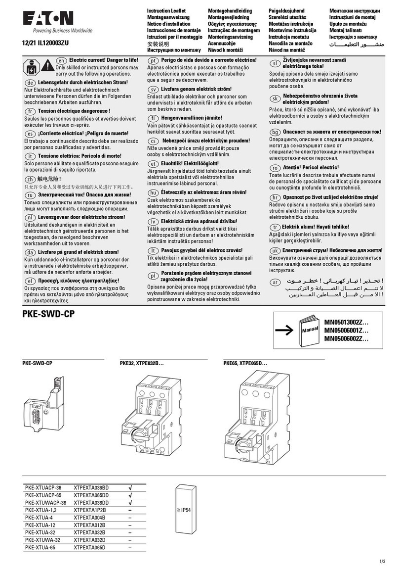
Eaton PKE-SWD-CP Instruction leaflet

Eaton

Eaton PKE-SWD-CP Instruction leaflet

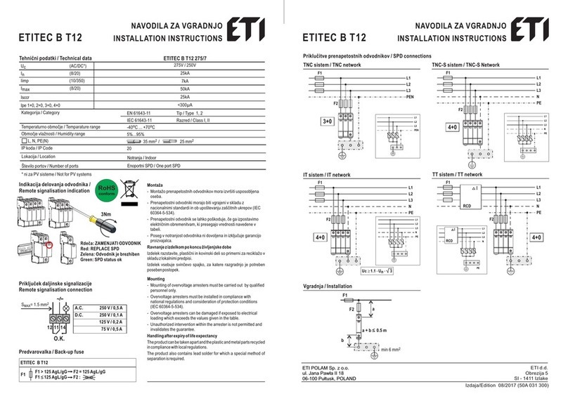
ETI ETITEC B T12 installation instructions

ETI

ETI ETITEC B T12 installation instructions

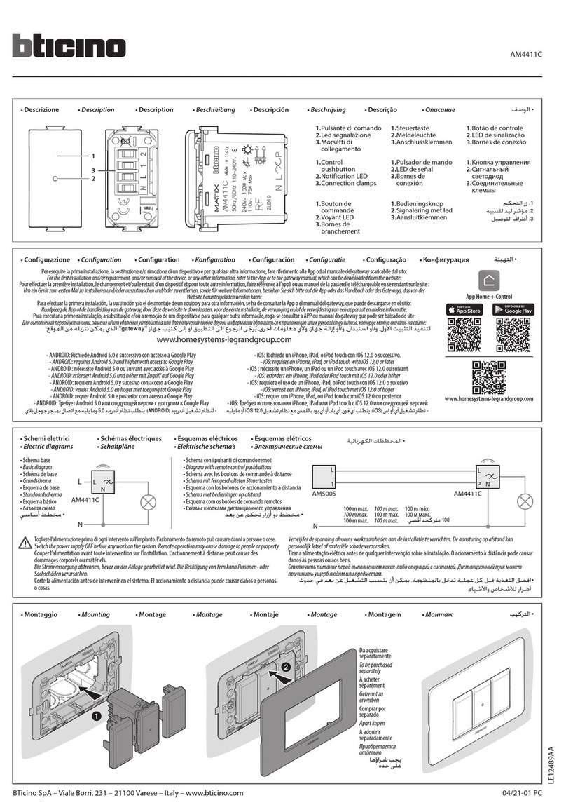
Bticino AM4411C manual

Bticino

Bticino AM4411C manual

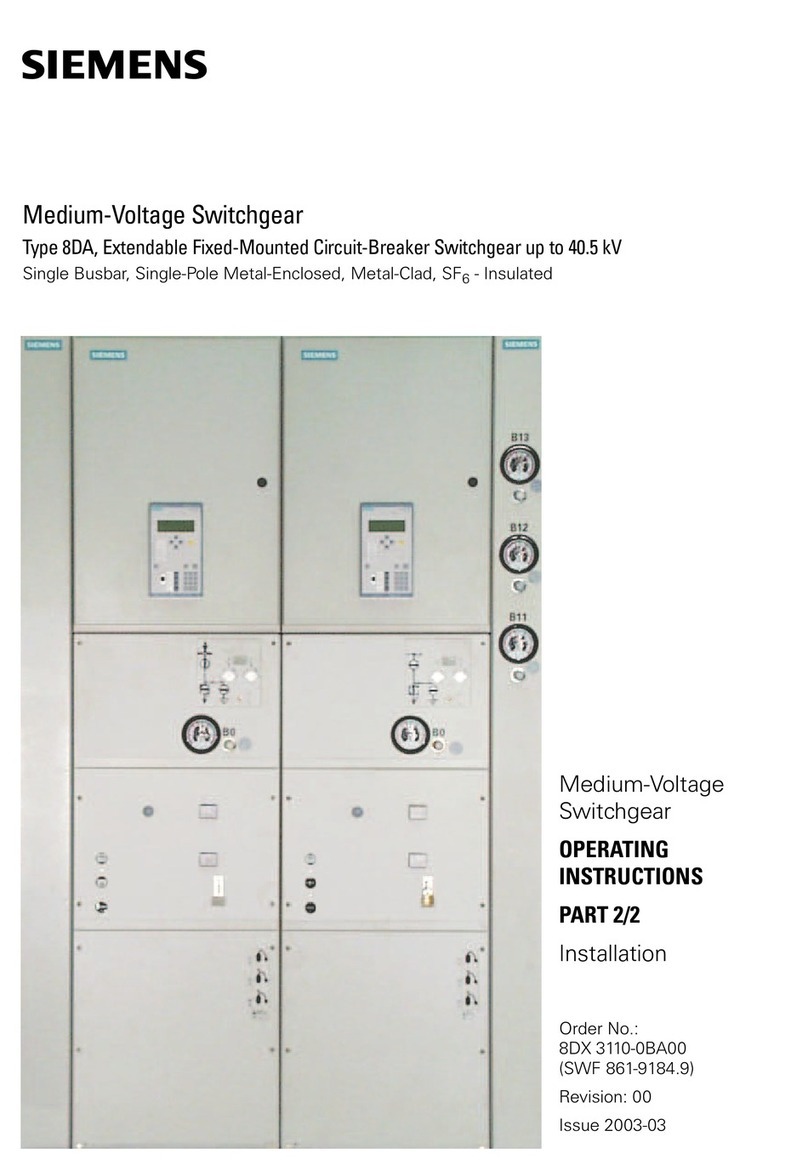
Siemens 8DA series operating instructions

Siemens

Siemens 8DA series operating instructions

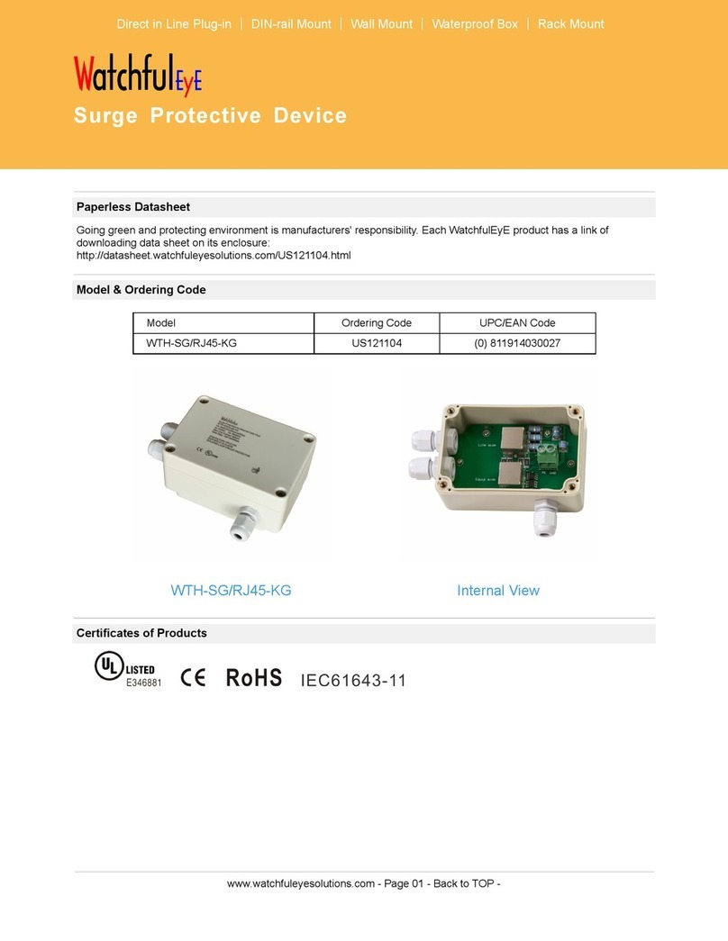
WatchfulEye WTH-SG/RJ45-KG manual

WatchfulEye

WatchfulEye WTH-SG/RJ45-KG manual

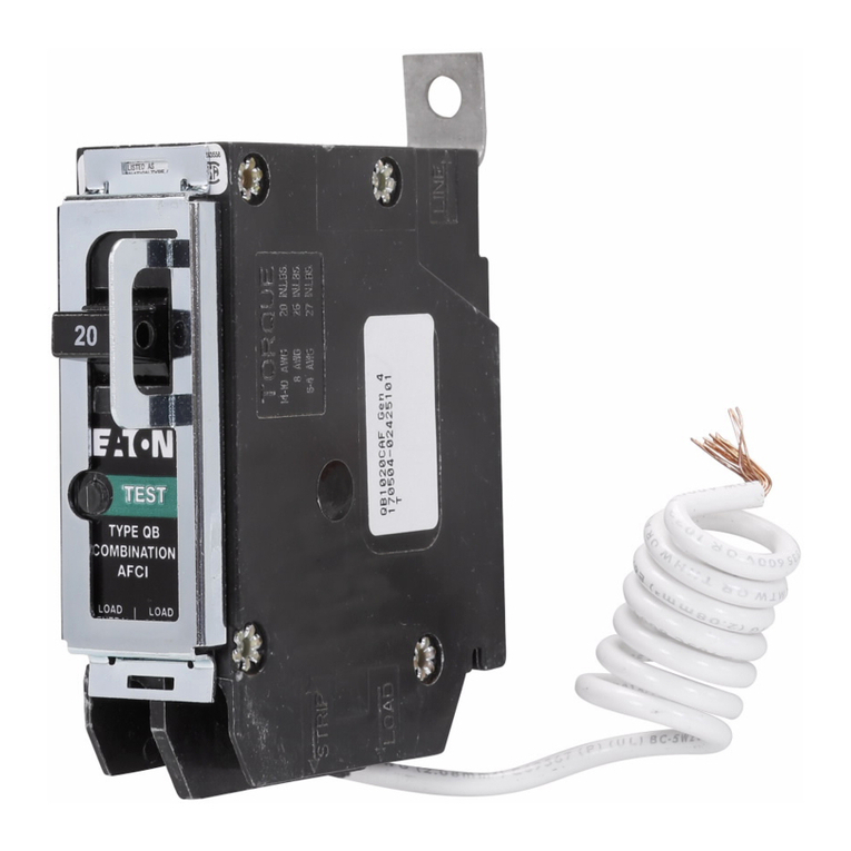
Eaton BRCAFLOFF Instructional Leaflet

Eaton

Eaton BRCAFLOFF Instructional Leaflet

Block ECONOMY SMART PC-FU/DC24 manual

Block

Block ECONOMY SMART PC-FU/DC24 manual

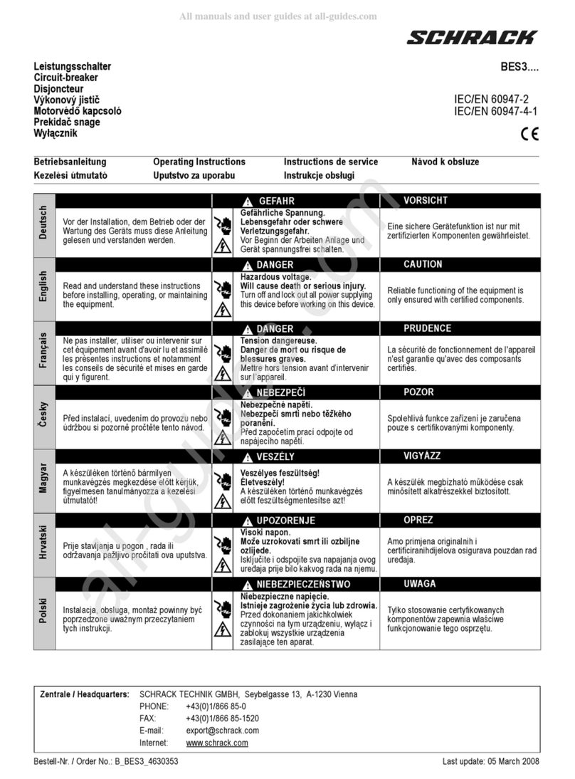
Schrack BES3 Series operating instructions

Schrack

Schrack BES3 Series operating instructions

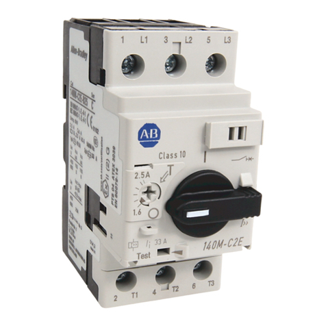
Allen-Bradley 140M-C-TRE installation instructions

Allen-Bradley

Allen-Bradley 140M-C-TRE installation instructions

Eaton DDC-800/2 Instruction leaflet

Eaton

Eaton DDC-800/2 Instruction leaflet

manuals.online logo
manuals.online logoBrands
  • About & Mission
  • Contact us
  • Privacy Policy
  • Terms and Conditions

Copyright 2025 Manuals.Online. All Rights Reserved.