manuals.online logo
Brands
  1. Home
  2. •
  3. Brands
  4. •
  5. Amphenol
  6. •
  7. Accessories
  8. •
  9. Amphenol Telaire Ventostat T8100 NS Series User manual

Amphenol Telaire Ventostat T8100 NS Series User manual

Telaire Ventostat™ T8100 NS and NSP Series
CO2Sensor
User Instructions
T63351-003
September 2014
Page 1 of 4
A
mphenol
Advanced Sensors
®
Installing the Sensor
!WARNING!
Before performing service or maintenance operations on
the systems, turn OFF main power switches to the unit.
Electric shock can cause personal injury. Please read and
follow the wiring instructions precisely; miswiring may
cause permanent damage to the product.
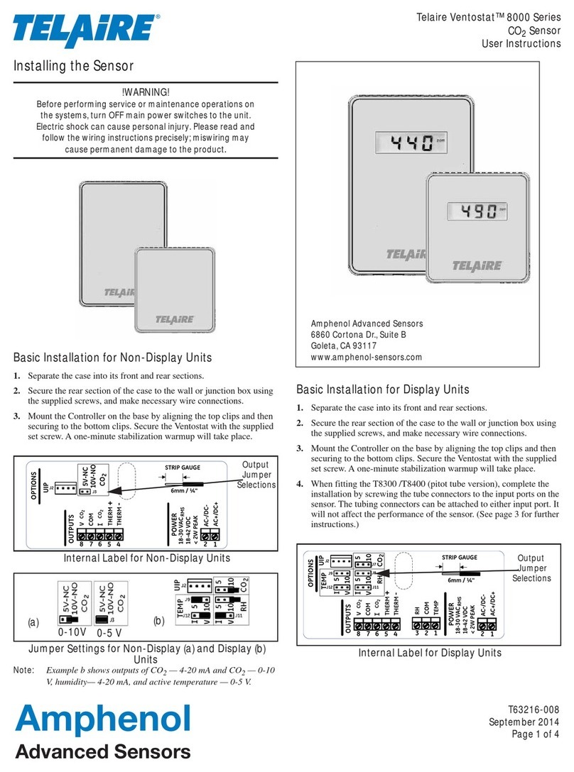
Basic Installation for T8100-NS and NSP
1. Separate the case into its front and rear sections.
2. Secure the rear section of the case to the wall or junction box using
the supplied screws, and make necessary wire connections.
3. Mount the Controller on the base by aligning the top clips and then
securing to the bottom clips. Secure the Ventostat with the supplied
set screw. A one-minute stabilization warmup will take place.
Internal Label
Amphenol Advanced Sensors
6860 Cortona Dr., Suite B
Goleta, CA 93117
www.amphenol-sensors.com
Page 2 Telaire Ventostat™ T8100 NS and NSP Series
T8100-NS/NSP Wiring Diagrams
The Ventostat T8100-NS and T8100-NSP family of products has two
basic configurations.
T8100-NS provides simultaneous voltage and current outputs for CO2,
an independent thermistor with Night Setback Override Button. The
button shorts the thermistor when depressed.
T8100-NSP provides simultaneous voltage and current outputs for CO2,
an independent thermistor with Night Setback Override Button and slide
Potentiometer that can be used to control thermostat set point. The slide
potentiometer has 0 KOhm value in the left position and 100 KOhm
value in the right position; the middle position corresponds to 50 KOhm
value.
The functional block diagram of T8100-NSP is presented in Figure 1.
The electrical circuits of thermistor, Night Setback Overage Button and
potentiometer have common signal between each other as shown in
Figure 1.
The electrical circuits of the CO2sensor power supply and outputs, from
one side and thermistor, Night Setback Override Button and
Potentiometer from the other, are electrically isolated from each other.
For electrical wiring and power supply requirements, these two
configurations are identical. The recommended wire gauge is 18-22
AWG (1.0 to 0.75 metric).
!WARNING!
Ventostat T8100-NS/NSP products have two
terminal pins that are connected inside the sensor
to a common/ground: pin #7 on the I/O terminal
blocks and pin #2 on the power block. Do NOT
connect positive (hot) 24 VAC power line to terminal
number 2 of the terminal block.
Caution!
The T8100 Ventostats are either 3-wire or 4-wire type
configurations, powered by either AC or DC voltage.
They are not 2-wire or loop-powered devices. Wiring
the units as 2-wire or loop-powered devices will
irreparably damage the sensors and void the
warranty.
Figure 1: T8100-NS/NSP Functional Block Diagram
Figure 2: T8100-NS/NSP Wiring for 3-Wire System,
AC Power
Figure 3: T8100-NS/NSP Wiring for 4-Wire System,
AC Power
AC-/DC-/GND
AC+/DC+
THERM
COM
POT (T8100 NSP only)
I CO2
GND
V CO2
12
6712
3
8
4 -20 mA
current source
0 -10/ 0 – 5V
voltage source
CO2 sensor
Thermistor
NS button
2
123876
1
_+
L1L2
18 - 30
VAC RMS
CO2 0 -10/5 V out
Jumper selectable
CO2 4-20 mA out
Use either or both
CO2 outputs
Thermistor 10 KΩ Type II
and Night Setback Button
Slide potentiometer
T8100-NSP only
Left – 0 KΩ Right – 100 KΩ
(+)
(+)
(“-“ common)
(“-“ common)
2
123876
1
_+
L1L2
18 - 30
VAC RMS
CO2 0 -10/5 V out
Jumper selectable
CO2 4-20 mA out
Use either or both
CO2 outputs
Thermistor 10 KΩ Type II
and Night Setback Button
(+)
(+)
Common
(ground)
(“-“ common)
(“-“ common)
Slide potentiometer
T8100-NSP only
Left – 0 KΩ; Right – 100 KΩ
Telaire Ventostat™ T8100 NS and NSP Series Page 3
Ventostat Specifications
Sensing Method
Non-dispersive infrared (NDIR) absorption
Gold-plated optics
Patented ABC Logic self calibration algorithm
CO2Measurement Range
T8100
0 to 2000 ppm (0 ppm = 0 V, 4 mA; 2000 ppm = 10/5V, 20 mA)
CO2 Accuracy
±30 ppm or 3% of reading, whichever is higher*
Power Supply Requirements
18-30 VAC RMS, 50/60 Hz, or 18 to 42 VDC, polarity protected
Power Consumption
Typical 0.7 W at nominal voltage of 24V AC RMS
Temperature Dependence
0.2% FS per °C (±0.11% per °F)
Stability
<2% of FS over life of sensor (15 years)
Pressure Dependence
0.135% of reading per mm Hg
Certifications
CE and RoHS compliant
Signal Update
Every 5 seconds
CO2 Warm-up Time
< 2 minutes (operational)
10 minutes (maximum accuracy)
Operating Conditions
32°F to 122°F (0°C to 50°C)
0 to 95% RH, non-condensing
*CO2accuracy statement excludes standard gas used for calibration that
has an accuracy of 2%. In addition, there is a potential digital to analog
error of up to 1%.
Storage Conditions
-40°F to 158°F (-40°C to 70°C)
Flammability Classification
UL94 5VA
Thermistor Type
NTC 10 Kthermistor
Thermistor Accuracy
±1°C (15° to 35°C)
Night Setback Override Button (NS and NSP)
Shorts the thermistor output when depressed
Slide Potentiometer (NSP Only)
Left (stop) 0k Ohms (±5k )
Center 50k Ohms (±7.5k )
Right (stop) 100k Ohms (±15 )
ABC Logic™ Self Calibration System
ABC Logic™ (Automatic Background Calibration) self calibration
allows the sensor to continually recalibrate itself when the indoor
concentrations drop to outside levels while the building is unoccupied.
Generally a building must be regularly unoccupied for 4 hours or more
for this self-calibration system to operate properly. Under these
conditions, ABC Logic™ should maintain sensor calibration over the
lifetime of the sensor. The ABC Logic™ should be turned OFF where a
building is continuously occupied 24 hours per day, or where there could
be significant sources of non-occupant related CO2such as greenhouses,
breweries and other industrial and food processing applications.
Output
Analog
0 to 5 V, (100 output impedance)
0 to 10 V (100 output impedance) and
4 to 20mA (RLmaximum 500 ) available simultaneously for CO2
output
Digital to analog error ±1%
Page 4 Telaire Ventostat™ T8100 NS and NSP Series
Warranty/Other
Warranty
18 months parts and labor
This product is covered by one or more of the following patents:
5,650,624 / 5,721,430 / 5,444,249 / 5,747,808 / 5,834,777 / 5,163,332 /
5,340,986 / 5,502,308 / 6,344,798 / 6,023,069 / 5,370,114 / 5,601,079 /
5,691,704 / 5,767,776 / 5,966,077 / 6,107,925 / 5,798,700 / 5,945,924 /
5,592,147 / 6,255,653 / 6,250,133 / 6,285,290
Warranty Repairs
Amphenol Thermometrics, Inc. will repair Telaire product that fails to
meet the terms provided for in the Return and Warranty Policy
Statement (See, http://www.amphenol-sensors.com).Warranty period
shall start from date of manufacture and be based on product category
and type of equipment as specified in Table 1: Product Warranty
Periods. For all warranty repairs, Amphenol Thermometrics, Inc. will
bear all product repair parts, labor, and standard ground shipping
charges.
Customer Support Centers
U.S.A.
Sales and Services
(Repair/Calibration):
Amphenol Thermometrics, Inc.
St Marys Center
967 Windfall Road
St Marys, Pennsylvania 15857
U.S.A.
T: +1 814-834-9140
F: +1 814-781-7969
U.K.
Sales and Service:
Amphenol Thermometrics (U.K.) Limited
Crown Industrial Estate Priorswood Road
Taunton, TA2 8QY, UK
T: +44 1823-335-200
Brazil
Sales and Service
Amphenol TFC DO Brazil LTDA
Rodovia Governador Adhemar
Pereira de Barros KM 121,5 S/N
13098-396 Campinas
Sao Paulo, Brazil
U.S.A.
Technical Support:
Amphenol Thermometrics, Inc.
St Marys Center
967 Windfall Road
St Marys, Pennsylvania 15857
U.S.A.
T: +1 814-834-9140
F: +1 814-781-7969
China:
Amphenol (Changzhou)
Connector Systems
305 Room, 5D
Jintong Industrial Park
Wujin, Changzhou, Jiangsu, China
T:+86 519 8831 8080 ext. 50087
F:+86 519 8831 2601
©2014 Amphenol Thermometrics, Inc. All rights reserved.
Technical content subject to change without notice.
www.amphenol-sensors.com
A
mphenol
Advanced Sensors
www.telaire.com

This manual suits for next models

1

Other Amphenol Accessories manuals

Amphenol Temposonics V EtherNet/IP R Series User manual

Amphenol

Amphenol Temposonics V EtherNet/IP R Series User manual

Amphenol Temposonics GB SSI Series User manual

Amphenol

Amphenol Temposonics GB SSI Series User manual

Amphenol Temposonics T Series User manual

Amphenol

Amphenol Temposonics T Series User manual

Amphenol Temposonics G Series Reference guide

Amphenol

Amphenol Temposonics G Series Reference guide

Amphenol Temposonics MH Series User manual

Amphenol

Amphenol Temposonics MH Series User manual

Amphenol Temposonics T Series User manual

Amphenol

Amphenol Temposonics T Series User manual

Amphenol Temposonics G Series User manual

Amphenol

Amphenol Temposonics G Series User manual

Amphenol SSI Digital Fluid-Trac DFT-200 Series User manual

Amphenol

Amphenol SSI Digital Fluid-Trac DFT-200 Series User manual

Amphenol Temposonics R V Analog Series User manual

Amphenol

Amphenol Temposonics R V Analog Series User manual

Amphenol Temposonics V POWERLINK R Series User manual

Amphenol

Amphenol Temposonics V POWERLINK R Series User manual

Amphenol Telaire Chipcap 2 User guide
Amphenol

Amphenol Telaire Chipcap 2 User guide

Amphenol Temposonics MH Series User manual

Amphenol

Amphenol Temposonics MH Series User manual

Amphenol Telaire Ventostat 8000 Series User manual

Amphenol

Amphenol Telaire Ventostat 8000 Series User manual

Amphenol Temposonics E-Series User manual

Amphenol

Amphenol Temposonics E-Series User manual

Amphenol Temposonics T Series User manual
Amphenol

Amphenol Temposonics T Series User manual
Amphenol Temposonics T Series User manual
Amphenol

Amphenol Temposonics T Series User manual
Popular Accessories manuals by other brands

Vishay TSSP770 Series manual

Vishay

Vishay TSSP770 Series manual

bsg PL192-112-072 instruction manual

bsg

bsg PL192-112-072 instruction manual

Soundsmith ZEPHYR MIMC Owner's manual and technical documentation

Soundsmith

Soundsmith ZEPHYR MIMC Owner's manual and technical documentation

Serene House Oracle 101205001 Instruction manual & warranty

Serene House

Serene House Oracle 101205001 Instruction manual & warranty

Banner L-GAGE LE250 IO-Link quick start guide

Banner

Banner L-GAGE LE250 IO-Link quick start guide

Extreme Networks BlackDiamond 6816 Installation note

Extreme Networks

Extreme Networks BlackDiamond 6816 Installation note

Hoval ServeCool operating instructions

Hoval

Hoval ServeCool operating instructions

PCWI DC30 Operator's handbook

PCWI

PCWI DC30 Operator's handbook

Axor Brushed Nickel 41333820 Specification sheet

Axor

Axor Brushed Nickel 41333820 Specification sheet

Profroid SOPRANO CO2 operating instructions

Profroid

Profroid SOPRANO CO2 operating instructions

Nordson 1007839A instruction sheet

Nordson

Nordson 1007839A instruction sheet

Active Tools 2k rowing shoe Installation use & care instructions

Active Tools

Active Tools 2k rowing shoe Installation use & care instructions

SIXTOL SX4004 Instructions for use

SIXTOL

SIXTOL SX4004 Instructions for use

Intermec 751G instructions

Intermec

Intermec 751G instructions

Rain Bird FS200B owner's manual

Rain Bird

Rain Bird FS200B owner's manual

Capital Play CAPITAL PRO MASTER installation manual

Capital Play

Capital Play CAPITAL PRO MASTER installation manual

Behringer U-CONTROL UCA200 operating manual

Behringer

Behringer U-CONTROL UCA200 operating manual

Rice Lake REVOLUTION 682 Synergy Plus Technical manual

Rice Lake

Rice Lake REVOLUTION 682 Synergy Plus Technical manual

manuals.online logo
manuals.online logoBrands
  • About & Mission
  • Contact us
  • Privacy Policy
  • Terms and Conditions

Copyright 2025 Manuals.Online. All Rights Reserved.