Amphenol RESMLAC 28 MG User manual

RESMLAC 28MG IG rev. 1.1 Page 1 of 14 Last Rev: 28-Nov-11
Amphenol – 948, Promenade de l‘Arve – B.P. 29 – 74311 THYEZ Cedex – France - +33(0)4.50.89.28.00 – www.rjswitch.com
Amphenol
RJ-Switch
IP67 rugged Ethernet Managed Switch
RESMLAC 28MG
- Installation Guide -
Contents
Section 1 General Information Page 3
Section 2 Hardware Page 4
Section 3 Installation Page 5
Section 4 Wiring Page 6
Section 5 Management Page 10
Section 6 Features Overview Page 11
Section 7 Service Information Page 14
Total Quality Standard Locations European Directives US Emissions
This manual applies to the following products:
RESMLAC 28 MG
Rugged IP67 Managed Ethernet Switch with 24 gigabit ports + 4 optional
fiber ports.
For options and detailed P/N, please consult us.
Révision Date Modifications
1.0 August 2011 Initial document
1.1 November
2011 Pinout of power connector.

RESMLAC 28MG IG rev. 1.1 Page 2 of 14 Last Rev: 28-Nov-11
Amphenol – 948, Promenade de l‘Arve – B.P. 29 – 74311 THYEZ Cedex – France - +33(0)4.50.89.28.00 – www.rjswitch.com
Amphenol Statement of Limited Warranty:
The characteristics of the Products shall be defined as those published in the most recent version of the Vendor's specifications,
unless different characteristics are expressly agreed between the Vendor and the Customer.
Unless expressly agreed to the contrary, the guarantee shall be valid for one year from the date of delivery.
The guarantee shall be made invalid:
Where the cover of the switch enclosure have been opened.
Where the components have been damaged in transit or have not been stored by the Customer in conditions in
accordance with the specification.
Where the components have been subjected to abuse (mechanical, electrical or thermal) on installation or on use and, in
the case of slices/dice, have been subjected to handing or such operations as the welding of connecting wires mounting
by soldering or sticking.
Where the unfitness or defectiveness of the components has resulted from exceeding the maximum values for usage
(temperature limit, maximum voltage, etc.) as defined by the Vendor, or from incorrect choice of application.
Furthermore, the guarantee shall not cover consequential liability, direct or indirect which may result from the failure of a
component supplied by the Vendor.
The foregoing constitutes the Vendor's guarantee in its entirely and takes the place of any other format guarantee, implied or
otherwise.
The guarantee is limited, at the Vendor's option, to either the replacement or the repair of the component accepted by him as
being defective, to the exclusion of any other from of compensations.
FCC Statement:
This equipment has been tested and found to comply with the limits for a Class B digital device, pursuant to Part 15 of the FCC
Rules. These limits are designed to provide reasonable protection against harmful interference in a residential installation. This
equipment generates, uses and can radiate radio frequency energy and, if not installed and used in accordance with the
instructions, may cause harmful interference to radio communications. However, there is no guarantee that interference will not
occur in a particular installation. If this equipment does cause harmful interference to radio or television reception, which can be
determined by turning the equipment off and on, the user is encouraged to try to correct the interference by one or more of the
following measures: Reorient or relocate the receiving antenna; Increase the separation between the equipment and receiver;
Connect the equipment into an outlet on a circuit different from that to which the receiver is connected; Consult the dealer or an
experienced radio/TV technician for help.
CE Declaration of conformity:
This equipment complies with the requirements relating to electromagnetic compatibility, EN 55022 class B for ITE and EN
50082-1.
This meets the essential protection requirements of the European Council Directive 89/336/EEC on the approximation of the
laws of the Member States relating to electromagnetic compatibility.
Copyright & Trademarks:
Copyright Amphenol, All Rights Reserved.
Note: All information in this document is subject to change without notice.

RESMLAC 28MG IG rev. 1.1 Page 3 of 14 Last Rev: 28-Nov-11
Amphenol – 948, Promenade de l‘Arve – B.P. 29 – 74311 THYEZ Cedex – France - +33(0)4.50.89.28.00 – www.rjswitch.com
Section 1 General Information
Overview
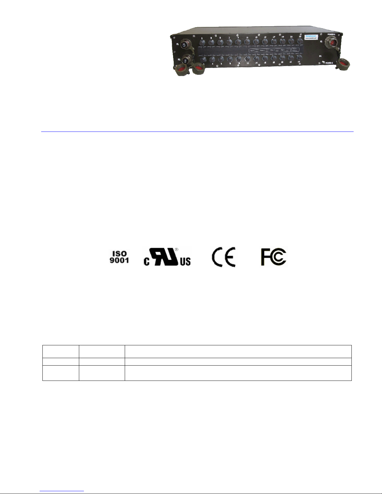
This manual will help you install and maintain the 28 ports Amphenol Rugged Ethernet
Gigabit Managed switches.
Military applications can now take full advantage of 1000Mbps Gigabit Ethernet
performance.
The installation guide describes how to install and use the hardened Ethernet
RESMLAC28MG Military Rugged Switch. Capable of operating at extreme temperature
of -35°C to +75°C and meet the toughest industrial and military environments such as
MIL-STD-810F, MIL-STD-1275B, MIL-STD-461E up to the highest levels. The
mentioned ability turns the RESMLAC28MG to the optimal solutions switch of choice for
harsh environments constrained by space.
Developed for military and harsh mobile applications, the RESMLAC28MG features
mechanical packaging enhancements designed for MIL-STD-810F airborne and ground
environmental compliance and high reliability. The unit has been especially hardened to
improve ingress, impact, and shock/vibration protection, as well as eliminate all moving
parts through passive cooling, and interface through sealed MIL-D-38999 and SCE
TERRAPIN circular connectors.
Leveraging best-in-class switching technology from Techaya, the RESMLAC28MG serves
as a robust solution for providing local area network (LAN) connectivity to IP-enabled
computing and net-centric devices. Compact in size, the RESMLAC28MG is particularly
useful for expanding port density to tactical IP routers in space-constrained airborne and
ground vehicle environments.
RESMLAC28MG is specifically designed for Data Acquisition & Transmission,
Battlefield Communication C4ISR, Rugged Networks, Mobile Communications, Combat
vehicles and Avionic & Shipboard Systems.
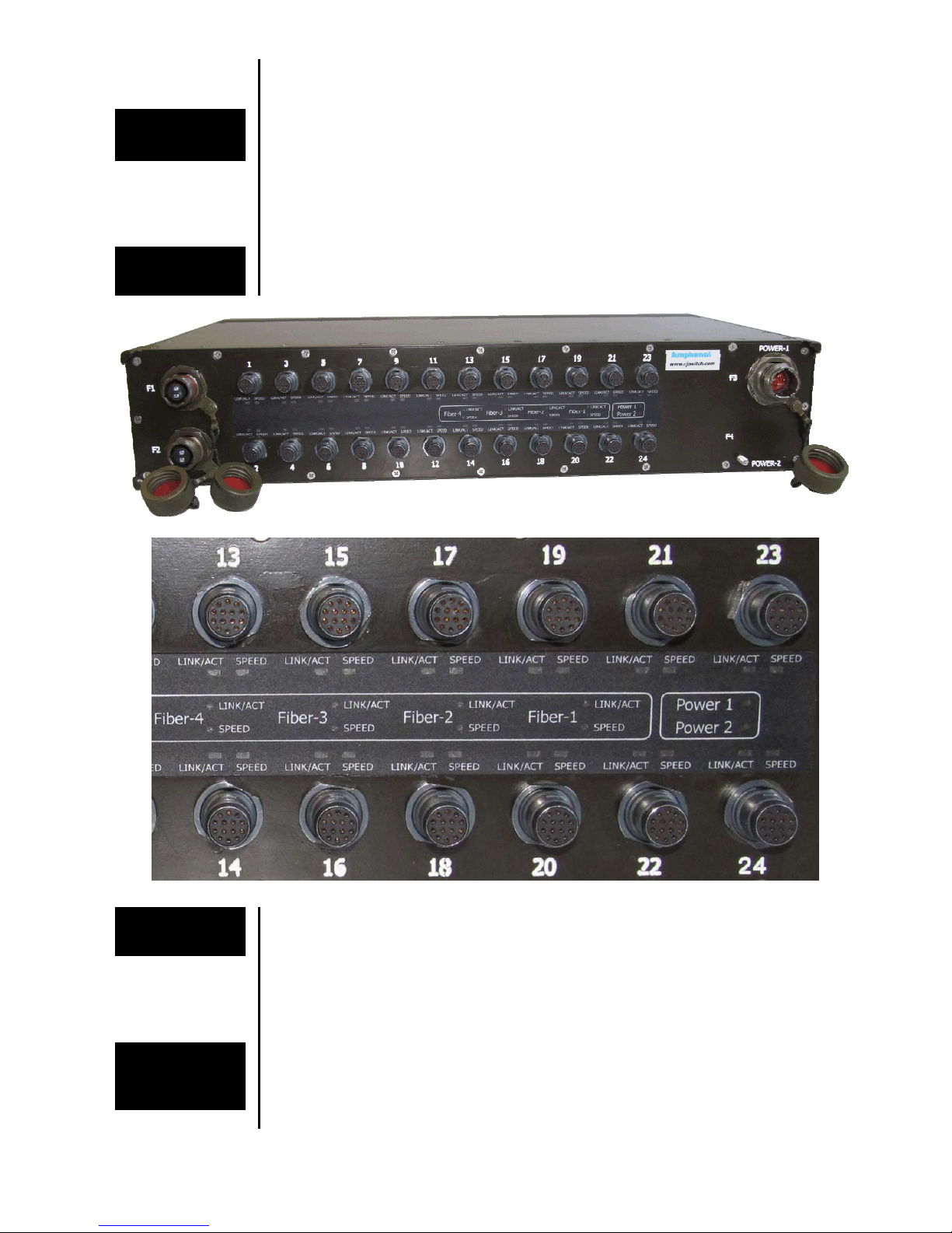
Operation
The switch supports triple speed 10/100/1000BaseTx (up to 1000 Mbps) for each of the 24
ports. Each of these ports will independently auto-sense the speed, allowing you to
interface to regular, fast or gigabit Ethernet devices.
The switch offers also 4 combo ports providing alternative 4 ports 100/1000Base-FX.
These ports withstands up to 10 Gbps.
Performance
Specifications
These general specifications apply to these switches. Refer to Section 5 for complete
technical specifications.
Copper Ports 24x 10/100/1000BaseT(x) (Shielded SCE Terrapin connectors)
Fiber ports 4x optional combo fiber ports up to 10Gbps rated
Voltage 24Vdc Nominal (18-32V)
Power Consumption: 20W Typical
Ethernet Standards IEEE 802.3 (10BaseT), 802.3u (100BaseTX), 802.3x (Full
Duplex), 802.3z (Gigabit)
IEEE 802.1x MAC based Authentication
IEEE 802.1Q Vlan Tagging
IEEE 802.1P QoS
IEEE 802.1S Multiple STP
IEEE 802.1W Rapid STP
IEEE 802.1AD Link Aggregation
MIL standards MILSTD-1275, MILSTD-461E, MILSTD-810F GM, IP67
Electromagnetic MIL-STD-461E Electromagnetic compatibility
CE-102, CS-114, CS-115, CS-116, RE-102, RS-103
Operating Temp. -35ºC to +75ºC (-31ºF to +167ºF) – Cold Start-Up
Waterproof IP67

RESMLAC 28MG IG rev. 1.1 Page 4 of 14 Last Rev: 28-Nov-11
Amphenol – 948, Promenade de l‘Arve – B.P. 29 – 74311 THYEZ Cedex – France - +33(0)4.50.89.28.00 – www.rjswitch.com
Section 2 Hardware
Overview
The switches can be mounted directly to a flat surface or to a wall. Refer to the mechanical
drawing below. Its high protected enclosure makes it able to withstand immersion (IP67
rating).
The Ethernet connections come out from rugged MIL-DTL-38999 serie III connectors for
power and fiber and with SCE Terrapin connectors for Ethernet.
Front Panel
Display The following describes the front panel, and LED indicators of the RESMLAC28MG.
LED Indicators
for Power
The Single Power 1 and Power 2 Led indicators on the front panel provide the operative
status of the switch. Some models come with only 1 power supply, some come with 2
separate power supplies.
On models with only 1 power supply, only Power 1 LED indicator will be operational.
Once the LED is turned on, the switch is powered and ready-for-use.
This LED will be ON solid green when proper power has been applied to the unit.
LED indicators
for Ethernet
ports
Each port has 2 LEDs indicators:
Link / Activity (Off – there is no link, Steady Green – There is a device connected,
Flashing Green – there is data transmission)
Speed (Steady Green for 1000Mbps, Off for 100 and 10 Mbps)

RESMLAC 28MG IG rev. 1.1 Page 5 of 14 Last Rev: 28-Nov-11
Amphenol – 948, Promenade de l‘Arve – B.P. 29 – 74311 THYEZ Cedex – France - +33(0)4.50.89.28.00 – www.rjswitch.com
Section 3 Installation
Selecting a
Site
As with any electronic device, you should place the switch where it will not be subject to
extreme temperatures, humidity, or electromagnetic interference that exceeds the
RESMLAC28MG‘s profile. Specifically, the site you select should meet the following
requirements:
The ambient temperature should be between -35 to 75 degrees Celsius.
The relative humidity is recommended to be less than 95% percent, non-
condensing.
Surrounding electrical devices should not exceed the electromagnetic field (RFC)
standards for MIL-STD-461E.
The switches are pre-equipped with plastic or metallic caps on all ports, including power
and Ethernet.
Make sure all connectors are protected with cap or sealed plug to
ensure sealing and prevent from deterioration of the contacts.
Mounting The RESMLAC28MG Ethernet Switch can be fastened to any flat surface by mounting the
box directly or installed inside a 19’’ rack. Refer to the mechanical drawings below. Make
sure to allow enough room to route your Ethernet and power cables.
Two types of brackets are available:
Type A for 19’’ rack mounting
Type B for mounting on any flat surface. By default type B is proposed.
6x Screws with flat and spring washer are needed to fix the brackets onto the switch.
Screw type: Pan head screw #8-32 UNC - 0.5” stainless steel
Brackets type A for rack 19’’ mounting
Brackets type B for flat surface mounting

RESMLAC 28MG IG rev. 1.1 Page 6 of 14 Last Rev: 28-Nov-11
Amphenol – 948, Promenade de l‘Arve – B.P. 29 – 74311 THYEZ Cedex – France - +33(0)4.50.89.28.00 – www.rjswitch.com
Section 4 Wiring
Overview
These switches provide connections to Ethernet devices in harsh environment. Typically a
port is used to connect to another Ethernet switch or hub that is connected to the main
Ethernet backbone. The other Ethernet ports are then connected to Ethernet devices such
as communication systems, Ethernet I/O, or industrial computers. Electrical isolation is
provided on the Ethernet ports for increased reliability.
Please follow normal Ethernet wiring practices when installing these switches.
Power plug
wiring The switches should be powered using mating plugs and backshells compliant with MIL-
DTL-38999 series III. We suggest using hereunder accessories. Another backshell can be
used but it must ensure a correct sealing protection.
Power plug
part number Military designation: JD38999/26WC4SN
Amphenol designation: TV06RW1304S
This plug is size 13. It is coming with 4 contacts size 16 (13 A nominal current).
Power plug
wiring
Contact Signal Suggested Harness Color
A 24 V (+) red
B Not connected Not connected
C 24 V (-) black
D Not connected Not connected
Note: cable assemblies where both A and B are connected to 24V+ and both C and D are
connected to 24V- are accepted.
Tooling The plugs are using crimp contacts size 16.
We suggest using hereunder tooling.
Crimping tools Amphenol No Military No
Crimping tool 809857 M22520/1-01
Positioner 809858 M22520/1-04
Plastic insertion and
removal tools
Colour Amphenol No Military no
Blue 809855 M81969/14-03

RESMLAC 28MG IG rev. 1.1 Page 7 of 14 Last Rev: 28-Nov-11
Amphenol – 948, Promenade de l‘Arve – B.P. 29 – 74311 THYEZ Cedex – France - +33(0)4.50.89.28.00 – www.rjswitch.com
Backshell We suggest using TVNSA backshells with corresponding heat shrinks to come with
the TV06RW1304S plug for power..
These backshells, providing an electrical continuity between cable and connector,
ensure a high level or of EMI/RFI protection. The sealing is ensured by straight heat
shrink molded piece at the rear of the backshell. NSA and SA backshells ensure the
shielding by clamping the braid with a screwing system. The free inner ring avoids
twisting of the braid during screwing.
Heat-shrinks are molded pieces for harsh environment, fluid resistant (with
preinstalled adhesive).
Backshell designation: TVNSA 13 014
Heat shrink designation: 804223
TVNSA backshell dimensions
Plug size A length
mm (in) A thread
Metric B max
mm (in) C max
mm (in) Ø E max
mm (in) Ø G max
mm (in)
13 (C) 35.60
(1.402) M18x1.0
-6H 22.70
(0.894) 12.70
(0.500) 21.64
(0.852) 22.60
(0.890)
TVNSA backshell assembly instruction
1. Prepare the cable for termination process and slide onto
the cable the items in the order shown on figure 1.
2. Screw the backshell at the rear of the connector.
3. Fold back the braid on the outer jacket and fix it (figure
2).
4. Install the braid as shown on figures 3 and 4:
Release the braid and cover the backshell (a) and the
connector’s shell. Slide the first ring (b) over the braid.
Fold back the braid on the ring (b) and slide the second ring
(c) over the braid and the first ring (b). Screw the last ring
(d) at the rear of the backshell. If necessary, fix the extra
braid on the outer jacket of the cable. If this installation
(double folding of the braid) is not possible, refer to figure
5: Slide the first ring (b).
Release the braid and cover the backshell (a) and the
connector’s shell. Cut the braid as shown. Slide the second
ring (c) over the braid and the first ring (b).
Screw the last ring at the rear of the backshell.
5. Install the heat-shrink molded piece.

RESMLAC 28MG IG rev. 1.1 Page 8 of 14 Last Rev: 28-Nov-11
Amphenol – 948, Promenade de l‘Arve – B.P. 29 – 74311 THYEZ Cedex – France - +33(0)4.50.89.28.00 – www.rjswitch.com
Ethernet plug
wiring These switches provide connections to Ethernet devices on the battlefield. Typically a
port is used to connect to another Ethernet switch or hub that is connected to the main
Ethernet backbone. The other Ethernet ports are then connected to Ethernet devices such
as communication systems, Ethernet I/O, or industrial computers. Electrical isolation is
provided on the Ethernet ports for increased reliability.
Please follow normal Ethernet wiring practices when installing these switches.
Ethernet plug
part number The switches should be connected using mating inline
receptacles from SCE Terrapin series.
We suggest using the L1K Latch inline receptacle or 01K
Snatch inline receptacle.
P/N for the latch inline receptacle: SCE2-B-L1K07-14PN.
Note: A grounding ring is provided with the 985 option.
P/N for the latch inline receptacle with grounding ring:
SCE2-B-L1K07-14PN-985.
This plug has size 7. It is coming with 14 contacts 23 AWG
with solder termination. Only contacts A to H should be
connected following to below wiring.
SCE2-B-LIK07-14PN
pinout
- Rear view -
Ethernet plug
pinout Use data-quality (not voice-quality) twisted pair cable rated
category 5e (or better) with standard RJ45 connectors.
Wiring of Ethernet cordsets shall respect following table.
(T568B colour code).
SCE2 RJ-45 Signal type Colour
A 1 Tx 2 White / Orange
B 2 Rx 2 Orange
C 3 Tx 3 White / Green
D 4 Rx 1 Blue
E 5 Tx 1 White / Blue
F 6 Rx 3 Green
G 7 Tx 4 White / Brawn
H 8 Rx 4 Brawn
Accessories Accessories such as heatshrinks boots, braid retention strap and metal dust caps can be
offered. Consult the TERRAPIN catalog for further details.
Here are the heatshrinks suggested for using with SCE2-B-L1K07-14PN:
Right angled or
Straight boot Amphenol P/N Raychem Tyco P/N Hellerman P/N
Straight 123GB-0798-07-S 202K132-25/225 154-44-GW24
Right angled 123GB-0798-07-R 202D132-25/225 1107-4-GW24

RESMLAC 28MG IG rev. 1.1 Page 9 of 14 Last Rev: 28-Nov-11
Amphenol – 948, Promenade de l‘Arve – B.P. 29 – 74311 THYEZ Cedex – France - +33(0)4.50.89.28.00 – www.rjswitch.com
DB9 plug
wiring These switches can be accessed with a serial connection.
The serial port is available only on port 1.
SCE to DB9
cordset To access the switch using a serial link, we suggest
preparing a cordset SCE to DB9.
The DB9 shall be female connector.
Use a latch inline receptacle for the SCE connector.
P/N : SCE2-B-L1K07-14PN.
This plug has size 7. It is coming with 14 contacts 23 AWG
with solder termination. Only contacts M, N and P should
be connected following to enclosed wiring.
SCE2-B-LIK07-14PN
pinout
- Rear view -
Suggested
cordset
Cordset Wiring SCE2 DB-9 Signal type
M 2 Rx
N 3 Tx
P 5 GND

RESMLAC 28MG IG rev. 1.1 Page 10 of 14 Last Rev: 28-Nov-11
Amphenol – 948, Promenade de l‘Arve – B.P. 29 – 74311 THYEZ Cedex – France - +33(0)4.50.89.28.00 – www.rjswitch.com
Section 5 Management
Accessing to
the switch You can access to the switch with 3 ways:
Web interface
Hyper Terminal / Console / CLI
Telnet
Each access method is independent and can be used separately.
After accessing the switch, use the Techaya MILTECH-9028 Users manual for details
regarding management features with CLI.
The web interface comes with an on-line help.
Web
Interface Web interface access requires that you know the IP address of the switch.
Use any of the 24 ports to connect to your computer.
Change your computer’s IP address to the same subnet before trying accessing the switch.
The default IP address of the switch is 192.168.1.111.
The default subnet mask is 255.255.255.0.
The User Name is “admin”.
The password is “admin” or blank/empty.
Hyper
Terminal Hyper Terminal access requires connecting the SCE/DB9 cordset to the port 1 of the
switch.
Open HyperTerminal and configure its properties with:
Bits per second: 115200
Data bits: 8
Parity: None
Stop bits: 1
Flow control: None
Telnet Telnet access requires enabling the telnet option via the web interface of via the CLI.
Then you can access to Telnet using the switch IP address.

RESMLAC 28MG IG rev. 1.1 Page 11 of 14 Last Rev: 28-Nov-11
Amphenol – 948, Promenade de l‘Arve – B.P. 29 – 74311 THYEZ Cedex – France - +33(0)4.50.89.28.00 – www.rjswitch.com
Section 6 Features Overview
Switching
Features Here’s a brief explanation of some of the features found in these switches documented by
this manual.
ETHERNET PORTS
24 x switched 10/100/1000 (Triple speed Ethernet) ports
4 Gigabit Combo ports for fiber up to 10G per port
STANDARDS COMPLIANCE
IEEE 802.3 10 Mbps 10BASE-T (Ethernet)
IEEE 802.3u 100BASE-TX 100 Mbps (Fast Ethernet)
IEEE 802.3x Full Duplex
IEEE 802.3z 1000BASE-TX (Gigabit Ethernet)
IEEE 802.1x MAC based Authentication
IEEE 802.1Q Vlan Tagging
IEEE 802.1P QoS
IEEE 802.1S Multiple STP
IEEE 802.1W Rapid STP
IEEE 802.1AD Link Aggregation
STANDARDS
MILSTD-1275B
MILSTD-461E: CE-102, CS-114, CS-115, CS-116, RE-102, RS-103
MILSTD-810F GM
IP67
Support up to 50ms holdup time, and 6VDC drops
CHASSIS
Low profile rugged aluminum extrusion
Conductively cooled w/custom internal heat-sinks
Ingress protection against sand, dust and moisture
Anodize Coating, MIL-A-8625, Type II, Class 2
PERFORMANCE
96.8 Mbps wire speed forwarding rate
56 Gbps maximum forwarding bandwidth
8K MAC Address

RESMLAC 28MG IG rev. 1.1 Page 12 of 14 Last Rev: 28-Nov-11
Amphenol – 948, Promenade de l‘Arve – B.P. 29 – 74311 THYEZ Cedex – France - +33(0)4.50.89.28.00 – www.rjswitch.com
NETWORKING - GENERAL
Wire-speed hardware-based 28 ports gigabit ethernet switch
Multicasting (IGMP Snooping), GARP, GMRP, MLD and GVRP.
Multicast groups up to 8K for both IPv4 and IPv6
Broadcasting and flooding Control up to 8K Groups
802.1q Tagged based VLAN up to 4K VLAN groups
Bridge support for VLAN Q-in-Q
Link Aggregation 802.3ad, up to 16 members in group
Link Aggregation mechanism based on L2/ L3/ L4 parameters.
Jumbo Frame support up to 10K
WEB, CLI, Telnet Management.
NETWORKING – QUALITY OF SERVICE
QoS Multi-Layer Classifier: 802.1p, EtherType, VLAN-ID, IPv4/6 DSCP/ToS,
and UDP/TCP ports & ranges traffic classification.
Per port WFQ and Strict Queuing scheduling
DSCP remarking for both IPv4 and IPv6 frames
Ingress policer and ingress shaper per port with 500Kbps granularity
Egress shaper per port with 500Kbps granularity
Full-duplex flow control (IEEE802.3X) and half-duplex backpressure, symmetric
and asymmetric
NETWORKING – SECURITY
Security via Radius Authentication 802.1x, Port / MAC access control
Port Security
Per port ingress and egress port mirroring.
Mirroring per VLAN and per content awareness match
Private VLAN support per VLAN (Isolated and Promiscuous ports)
Content Aware Policiers:
o128 Content Aware Policers
o16 Content Aware rate policers with rates from 1fps to 32 million fps
o8 UDP/TCP port range policers
oAdvanced ACL through hardware based match patterns
oContent Aware Policers for generic MAC, ARP, IPv4, IPv6 protocols
oNo restriction on any mix of entries to Content Aware Policers
oContent Aware Policers actions are permit/deny, police, count, snoop and
mirror
oSpecial support for IP fragments, UDP/TCP port ranges and ARP
oExtensive CPU DoS prevention
oSurveillance functions by Content Aware Policers counters
oMultiple ACLs per port for optimal usage of Content Aware Policers

RESMLAC 28MG IG rev. 1.1 Page 13 of 14 Last Rev: 28-Nov-11
Amphenol – 948, Promenade de l‘Arve – B.P. 29 – 74311 THYEZ Cedex – France - +33(0)4.50.89.28.00 – www.rjswitch.com
Storm controllers for flooded broadcast, multicast and Unicast
NETWORKING – REDUNDANCY AND RING PROTECTION
Spanning Tree (802.1d), RSTP (802.1w) and multiple Spanning Tree (802.1S)
for fast recovery rings
RPR for up to 30 units per ring with recovery time <50ms hardware based
20-Gbps bandwidth for ring topology
QoS consistency across stack / ring
Mirroring across stack / ring
Link aggregation groups spanning multiple switches in stack / ring
POWER
Voltage Input: 24Vdc Nominal (18-32V)
Option for Redundant Power Supply with load sharing, 48VDC and 90~230VAC
Power Consumption: 20W Typical
Exceed MIL-STD-1275B and MIL-STD-704A Surge and Spike protection with
50ms holdup time and 6VDC drops
Chassis grounding
SHOCK/VIBRATION/HUMIDITY
MIL-STD-810F; 501.4I, 501.4II, 502.4I, 502.4II, 507.4, 500.4II, 514, 516I,
516VI, 514.5, 512.4
IP67
PHYSICAL
Dimensions: 440mm (L) x 200mm (W) x 88mm (H), including connectors &
hardware, 2U, 19’’ rack
Weight: 5.6kg
Set of 6.5mm mounting holes on bottom for mounting to any flat surface.
19’’ standard mounting ears
COOLING
No Moving Parts. Passive Cooling
OPERATING TEMP
-35ºC to +75ºC (-31ºF to +167ºF) – Cold Start-Up
STORAGE TEMP
-45ºC to +85ºC (-49ºF to +185ºF)

RESMLAC 28MG IG rev. 1.1 Page 14 of 14 Last Rev: 28-Nov-11
Amphenol – 948, Promenade de l‘Arve – B.P. 29 – 74311 THYEZ Cedex – France - +33(0)4.50.89.28.00 – www.rjswitch.com
Section 7 Service Information
Service
Information
We sincerely hope that you never experience a problem with any Amphenol product. If you
do need service, call Amphenol at +33(0) 450 89 28 00 and ask for Applications
Engineering. A trained specialist will help you to quickly determine the source of the
problem. Many problems are easily resolved with a single phone call. If it is necessary to
return a unit to us, an RMA (Return Material Authorization) number will be given to you.
Amphenol tracks the flow of returned material with our RMA system to ensure speedy
service. You must include this RMA number on the outside of the box so that your return
can be processed immediately.
The applications engineer you are speaking with will fill out an RMA request for you. If the
unit has a serial number, we will not need detailed financial information. Otherwise, be sure
to have your original purchase order number and date purchased available.
We suggest that you give us a repair purchase order number in case the repair is not covered
under our warranty. You will not be billed if the repair is covered under warranty.
Please supply us with as many details about the problem as you can. The information you
supply will be written on the RMA form and supplied to the repair department before your
unit arrives. This helps us to provide you with the best service, in the fastest manner.
Normally, repairs are completed in two days. Sometimes difficult problems take a little
longer to solve.
We apologize for any inconvenience that the need for repair may cause you. We hope that
our rapid service meets your needs. If you have any suggestions to help us improve our
service, please give us a call. We appreciate your ideas and will respond to them.
For Your Convenience:
Please fill in the following and keep this manual with your Amphenol system for future
reference:
P.O. #:__________________ Date Purchased: ___________________
Purchased From:______________________________________________
Product
Support To obtain support for Amphenol products:
Visit our website. http.//www.rjswitch.com
Phone: +33(0) 450 89 28 00
Fax: +33(0) 450 96 29 75
E-mail: mailto:[email protected]
Mailing Address: Amphenol, Promenade de l’Arve, B.P.29, 74311 Thyez Cedex, France
For more
information You will find all useful information on the RJ-Switch series on the dedicated website:
http://www.rjswitch.com
Other manuals for RESMLAC 28 MG
1
Table of contents
Other Amphenol Network Router manuals