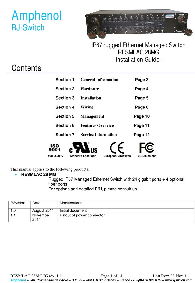
Amphenol RJS-ML-MG7F3G-CAPS User manual

Managed Switch Hardware Manual Page 1 of 14 Last Revised: 25-Jun-13
Amphenol – 948, Promenade de l‘Arve – BP 29 – 74311 THYEZ Cedex – France - +33(0)4.50.89.28.00 www.rjswitch.com
Amphenol
RJ-Switch
IP65/68 sealed Managed
Rugged Ethernet Switch
- ser Manual -
Contents
Section 1 General Information Page 4
Section 2 Installation Page 5
Section 3 Power Wiring Page 6
Section 4 Ethernet Wiring Page 9
Section 5 Technical Specifications Page 12
Section 6 Service Information Page 14
This manual applies to the following products:
•
RJS-ML-MG7F3G-(704)-(PSM)-(CAPS) - Managed IP68 Ethernet switch with 7x 10/100 Mbps
ports and 3 10/100/1000 Mbps ports, Olive drab cadmium plating on both receptacles and
enclosure
•
RJS-BKN-MG7F3G-(704)-(PSM)-(CAPS) - Managed IP68 Ethernet switch with 7x 10/100 Mbps
ports and 3 10/100/1000 Mbps ports, Black painted enclosure with nickel plated receptacles
Note: 704 = option: filter for power supply allowing better lightening protection
PSM = option: the switch is powered with 85-264 VAC instead of DC power
CAPS = option: the switch comes with caps fixed onto each receptacle

Managed Switch Hardware Manual Page 2 of 14 Last Revised: 25-Jun-13
Amphenol – 948, Promenade de l‘Arve – BP 29 – 74311 THYEZ Cedex – France - +33(0)4.50.89.28.00 www.rjswitch.com
Amphenol Statement of Limited Warranty:
Products shall benefit from a legal guarantee of one year following the date of delivery in accordance with the terms and
conditions indicated hereunder.
In all instances, Seller’s guarantee shall be limited to free replacement, in identical quantities, of the Product acknowledged
as defective by Seller with the exclusion of any compensation or damages and interests other than agreed in a specific
contract.
The guarantee is subject that Client notifies Seller of defect immediately following discovery thereof by any written means
during the legal guarantee period. Defective Products shall be returned to Seller in accordance with the same procedure as
that applicable to Products which do not comply with orders as indicated under article 9 hereinabove.
The following shall be excluded from the guarantees provided by Seller:
- Product defects resulting from inadequate maintenance, or supervision and, more widely, any use which does not comply
with written instructions of Seller and indicated in technical notices and/or product specifications, or default in respecting
applicable standards or professional customs and uses;
- Product defects resulting from an external cause or any modification or intervention by Client or third party without the
prior written consent of Seller;
- The guarantee shall not cover normal wear and tear of Products;
- Product defects resulting generally in whole or in part from damage or accidents attributable to Client or a third party;
- More specifically whether the cover of the switch enclosure have been opened.
- Whether the components have been damaged in transit or have not been stored by the Customer in conditions in
accordance with the specification.
- The guarantee shall not cover any defects resulting from instructions given by Client to Seller ;
- Whether the components have been subjected to abuse (mechanical, electrical or thermal) on installation or on use and, in
the case of slices/dice, have been subjected to handing or such operations as the welding of connecting wires mounting by
soldering or sticking.
- Whether the unfitness or defectiveness of the components has resulted from exceeding the maximum values for usage
(temperature limit, maximum voltage, etc.) as defined by the Vendor, or from incorrect choice of application.
- Damages resulting from force majeure, such as this is defined under article 11 of Amphenol Socapex Sales Conditions
hereunder, or resulting from any unpredictable event or natural disaster.
- Furthermore, the guarantee shall not cover consequential liability, direct or indirect which may result from the failure of a
component supplied by the Vendor.
Client shall retain sole and exclusive liability for the use of Products provided by Seller and the suitability thereof for use.
Client should ensure that its premises and storage conditions are adequate for the due and proper storage of Products and
ensure all safety guarantees as stipulated by regulations in force. No guarantee shall be provided by Seller in this regard.
CE Declaration of conformity:
This equipment complies with the requirements relating to electromagnetic compatibility and security.
EN55022 (Emissions);
EN55024 (EN50082-1 ou -2) et/ou EN61326-1 (Immunity);
EN61010-1 ou EN60950 (Electrical safety);
This meets the essential protection requirements of the European Council Directive 89/336/EEC on the approximation of
the laws of the Member States relating to electromagnetic compatibility.
Note: All information in this document is subject to change without notice.

Managed Switch Hardware Manual Page 3 of 14 Last Revised: 25-Jun-13
Amphenol – 948, Promenade de l‘Arve – BP 29 – 74311 THYEZ Cedex – France - +33(0)4.50.89.28.00 www.rjswitch.com

Managed Switch Hardware Manual Page 4 of 14 Last Revised: 25-Jun-13
Amphenol – 948, Promenade de l‘Arve – BP 29 – 74311 THYEZ Cedex – France - +33(0)4.50.89.28.00 www.rjswitch.com
Section 1
General Information
Overview
This manual will help you install and maintain the Amphenol Rugged Ethernet Managed
switches. Installation of the MG7F3G managed switches will enable the user to wire redundant
connections between nodes, manage the network by monitoring/gathering network data, allow for
browser or telnet configuration, increase network performance, and more.
Unlike an Ethernet hub that broadcasts all messages out all ports, these switches will intelligently
route Ethernet messages only out the appropriate port. The major benefits of this are increased
bandwidth and speed, reduction or elimination of message collisions, and deterministic
performance when tied with Unmanaged systems.
Note: This manual only covers the installation and wiring of these switches.
Please refer to the separate Software User Manual for managed switches for
details on configuring and using any of the management functions such as
SNMP, RSTP, IGMP, port mirroring, etc.
Refer also to the Ethernet Switch Tool’s comprehensive On-line help for more
details!
Managed
switch
Operation
Unlike a regular Ethernet switch, very resilient networks can be implemented because the Managed
Switch has the intelligence to detect and allow for ring Ethernet topologies. In other words,
implementing this switch will optimize the network for optimal bandwidth conditions, reduce the
number of collisions, and allow for redundant data path connections to reduce/eliminate downtime.
To further aid in network reliability and performance, SNMP is available to extract and exchange
network statistical information. Through the use of SNMP, various groups of statistical
information can be obtained such as TCP, RMON, IP, and more to aid the user’s job to extrapolate
the “health” of the network.
The Managed Switches can support 10BaseT (10 Mbps), 100BaseT (100 Mbps) and 1000BaseT
(1000Mbps) on their RJ45 ports (depending on the ports). Each of these ports will independently
auto-sense the speed, allowing you to interface to regular, fast or gigabit Ethernet devices.
Performance
Specifications
These general specifications apply to the Switches. Refer to Section 7 for complete technical
specifications.
10 Ethernet ports (shielded) 7x 10/100 plus 3x 10/100/1000 (with auto-negotiation, auto-crossover
and auto-polarity)
Ethernet Protocols All standard IEEE 802.3 (see Specifications for details)
Managed Ethernet Switch Type Managed with SNMP, RSTP, IGMP, VLANs and much more
Ethernet Isolation 1500 Volts RMS (for 1 minute)
Temperature Operating -40°C to +70°C
Storage -40°C to +85°C
Sealing IP65/68 2 m water for 24 hours
Shocks MIL-STD-810F 40g, 11ms, 18 saw tooth shocks
Surge and Spike protection
(with -704 option) MIL-STD-461E CE102 conducted emission
MIL-STD-704A 600V input transient, applied for 10µs
MIL-STD-1275A: Spikes: +/- 250 V for 100us
Surges: 100 V for 50 ms at 0.5 mohm
Ripple: 14VAC pk-pk)
Vibrations RTCA/DO-160C Sinusoidal vibrations 5-55 Hz: 0.01 inch ;
55-500 Hz: 1.5 g
Altitude MIL-STD-810F 50,000 ft – 15,000 m

Managed Switch Hardware Manual Page 5 of 14 Last Revised: 25-Jun-13
Amphenol – 948, Promenade de l‘Arve – BP 29 – 74311 THYEZ Cedex – France - +33(0)4.50.89.28.00 www.rjswitch.com
Section 2 Installation
Overview
All switches share the same footprint and can be mounted directly to a flat surface or to a wall. Refer
to the mechanical drawing below. Its high protected enclosure makes it able to withstand water jets
(IP65 rating) but also immersion until 2m depth for 24 hours (IP68 rating).
The Ethernet connections for all models come out from rugged MIL-DTL-38999 III connectors from
RJField range (see www.rjfield.com). Make sure to allow enough room to route your Ethernet cables.
Figure 3A – Mechanical Dimensions
Figure 3B – Mechanical Description

Managed Switch Hardware Manual Page 6 of 14 Last Revised: 25-Jun-13
Amphenol – 948, Promenade de l‘Arve – BP 29 – 74311 THYEZ Cedex – France - +33(0)4.50.89.28.00 www.rjswitch.com
Section 3 Power Wiring
Overview
The Managed Switches can be powered from the same DC source that is used to power your I/O
devices. The continuous voltage needs to be applied between the P1 and/or P2 terminal and the
Minus terminal (shown hereunder). The terminal GND should be tied to panel or chassis ground.
To reduce down time resulting from power loss, the Managed Switch can be powered redundantly.
2 contacts for power are available on the switch (P1 and P2). You may use only one or both up to
your need.
Refer to the DC Power diagram hereafter for wiring details.
Note: the P2 terminal is not available with -704 or PSM option.
Plugs and
backshells
The switches should be powered using mating plugs and backshells compliant with MIL-
DTL-38999 series III. We suggest using hereunder accessories. Another backshell can be
used but it must ensure a correct sealing protection.
Accessories part numbers
RJS-ML-MG7F3G (-options) RJS-BKN- MG7F3G (-options)
Plugs TV 06 RW 0935 S
(Size 9; using 6 contacts #22D)
TV S06 RF 0935 S
(Size 9; using 6 contacts #22D)
Suggested Backshells TVNSA 09 014 TVNSA 09 023
Heat shrinks 804221 804221
Crimping
tools
The plugs are using crimp contacts.
We suggest using hereunder tooling.
Crimping tools for all models
Amphenol No Military No
Crimping tool 809 801 M22520/2-01
Positioner 809 835 M22520/2-07
Contact insertion
and removal tool
(plastic) (*) 809 856 M81969/14-01
(*): Note: metallic tools are also available. Consult dedicated Tri-Start TV-CTV catalog (E113) for details.

Managed Switch Hardware Manual Page 7 of 14 Last Revised: 25-Jun-13
Amphenol – 948, Promenade de l‘Arve – BP 29 – 74311 THYEZ Cedex – France - +33(0)4.50.89.28.00 www.rjswitch.com
Wiring power
inputs
The diagrams below show the rear face of mating plugs.
The plugs to be used with the switches are from our TV series.
They are compliant with MIL-DTL-38999 series III.
In case you would like to power your switch using a redundant
power supply, we suggest using a second plug.
Note : the contact 6 is not connected.
Note: The use of 2 contacts P1 and P2 facilitates the cabling of redundant power inputs. It allows using an
additional backup battery.
Note: P2 and OK terminal are not active with -704 option. Only one connector shall be plugged.
Dimensions of acceptable wires
Contact size Gauge AWG
/ Section mm²
Outside diameter (mm)
min max Min Average Max
22D 28
0.095
22
0.38
0.76 1.20 1.37
Plugs dimensions
Plug size B Thread Class
2A (mm) Q Max (mm) V thread metric
9 (A) .6250 21.82 M12x1-6g

Managed Switch Hardware Manual Page 8 of 14 Last Revised: 25-Jun-13
Amphenol – 948, Promenade de l‘Arve – BP 29 – 74311 THYEZ Cedex – France - +33(0)4.50.89.28.00 www.rjswitch.com
Backshells
We suggest using TVNSA backshells with corresponding heat-shrinks. See previous page for
part numbers.
These backshells, providing an electrical continuity between cable and connector, ensure a
high level or of EMI/RFI protection. The sealing is ensured by straight heat-shrink molded
piece at the rear of the backshell. NSA and SA backshells ensure the shielding by clamping
the braid with a screwing system. The free inner ring avoids twisting of the braid during
screwing.
Heat-shrinks are molded pieces for harsh environment, fluid resistant (with preinstalled
adhesive).
TVNSA backshell dimensions
Plug size A length
mm (in) A thread
Metric B max
mm (in)
C max
mm (in)
Ø E max
mm (in)
Ø G max
mm (in)
9 (A) 35.60
(1.402)
M12x1.0
-6H
16.70
(0.658)
6.90
(0.272)
15.62
(0.615)
16.50
(0.650)
TVNSA backshell assembly instruction
1. Prepare the cable for termination process and slide
onto the cable the items in the order shown on figure 1.
2. Screw the backshell at the rear of the connector.
3. Fold back the braid on the outer jacket and fix it
(figure 2).
4. Install the braid as shown on figures 3 and 4:
Release the braid and cover the backshell (a) and the
connector’s shell. Slide the first ring (b) over the braid.
Fold back the braid on the ring (b) and slide the second
ring (c) over the braid and the first ring (b). Screw the
last ring (d) at the rear of the backshell. If necessary, fix
the extra braid on the outer jacket of the cable. If this
installation (double folding of the braid) is not possible,
refer to figure 5: Slide the first ring (b).
Release the braid and cover the backshell (a) and the
connector’s shell. Cut the braid as shown. Slide the
second ring (c) over the braid and the first ring (b).
Screw the last ring at the rear of the backshell.
5. Install the heat-shrink molded piece.

Managed Switch Hardware Manual Page 9 of 14 Last Revised: 25-Jun-13
Amphenol – 948, Promenade de l‘Arve – BP 29 – 74311 THYEZ Cedex – France - +33(0)4.50.89.28.00 www.rjswitch.com
Section 4 Ethernet Wiring
Overview
The Managed Switches provides connections to Ethernet devices on the battlefield. Typically the
gigabit port is used to connect to another Ethernet switch or hub that is connected to the main
Ethernet backbone. The other Ethernet ports are then connected to Ethernet devices such as PLCs,
Ethernet I/O, or industrial computers. Electrical isolation is provided on the Ethernet ports for
increased reliability.
RJ45 Wiring
Guidelines
Use data-quality (not voice-quality) twisted pair cable rated category 5 (or 5e for gigabit) with
standard RJ45 connectors. For best performance use shielded cable.
Please note that these cables are available as straight-thru or cross-over configurations. Either type
can be used because these switches support auto-MDI/MDIX-crossover.
Most standard Ethernet cordsets follow one of the TIA-568 guideline given hereafter.
RJ45 Cable
Distance
The maximum cable length for 10/100/1000BaseT is typically 100 meters (328 ft.).
Duplex
Operation
The RJ45 ports will auto-sense for Full or Half duplex operation, while the fiber ports are
configured for full duplex operation. Note: Fiber devices with half duplex settings should still
communicate with the switch. If otherwise then contact your switch vendor.
Network
Device Check
The Managed Switches are capable of supporting 10/100BaseT or 10/100/1000BaseT following to
the port. Make sure you connect the appropriate devices to each port.

Managed Switch Hardware Manual Page 10 of 14 Last Revised: 25-Jun-13
Amphenol – 948, Promenade de l‘Arve – BP 29 – 74311 THYEZ Cedex – France - +33(0)4.50.89.28.00 www.rjswitch.com
Ethernet
reinforced
plugs
The reinforced RJ45 plug is field installable and does not
require any special tools. It can be installed over any standard
Ethernet patch cable (though you may have to remove the latch
cover if it has an over-molded boot). Refer to the diagrams for
mechanical and assembly details.
This plug may be assembled with 4 different coding. Use the
coding A to make your assembly. For more details, please
consult:
http://www.rjfield.com/ethernet_connectors_rjf-tv_en.htm.
RJS-ML-MG7F3G RJS-BKN- MG7F3G
Ethernet Plug part number RJF TV 6 M G RJF TV 6 M N
Plating Olive drab Cadmium Nickel (RoHs compliant)
RJFTV6 plug dimensions and A coding
RJFTV6 plug assembly instructions
1- Push down the RJ45
cordset latch, and fix it
inside the insert.
2- Press in and click the
other part of the insert.
3- Insert in the metallic
housing. The RJ45
cordset latch should be at
the same position than the
main key of the shell to
meet the A coding.
Plug Receptacle
Code A

Managed Switch Hardware Manual Page 11 of 14 Last Revised: 25-Jun-13
Amphenol – 948, Promenade de l‘Arve – BP 29 – 74311 THYEZ Cedex – France - +33(0)4.50.89.28.00 www.rjswitch.com
CAPS for
Ethernet ports The models of switches with –CAPS (example: RJSML-MG7F3G-CAPS) termination
are pre-equipped with caps on all ports, including power and Ethernet.
The models without –CAPS termination (example: RJSML-MG7F3G) do not have caps
on ports. The required number of caps may be ordered separately as accessories.
In the case you order the cap separately, it may be
screwed directly on the receptacle.
Note: The screw comes with the cap.
Part numbers for Ethernet ports caps
RJS-ML-MG7F3G RJS-BKN-MG7F3G
Ethernet Plug part number RJS ML C7G RJS ML C7 N
Plating Olive drab Cadmium Nickel (RoHs compliant)

Managed Switch Hardware Manual Page 12 of 14 Last Revised: 25-Jun-13
Amphenol – 948, Promenade de l‘Arve – BP 29 – 74311 THYEZ Cedex – France - +33(0)4.50.89.28.00 www.rjswitch.com
Section 5 Technical Specifications
Technical
Specs
Here are the technical specifications for the Ring and Managed Switches covered by this manual.
General Specifications:
Ethernet switch type Managed with 10 Ethernet ports
Latency for 10 Mbps ports 16 us + frame time (typical) Varies on load and settings
Latency for 100 Mbps ports 5 us + frame time (typical)
Full or half duplex operation Configurable per port
“OK” Output
MG7F3G: ON if P1 and P2 have power and switch software is running
MG7F3G-704: ON when software is running
MG7F3G-PSM: ON when software is running; output power: 24VDC
OK Output Voltage
MG7F3G: Same as switch input voltage
MG7F3G-704: Same as switch input voltage
MG7F3G-PSM: output voltage: 24VDC
Maximum current output 0.5 Amp
Environmental Direct panel or wall mounting
Input power 7.0 W (typical - all ports active at 100 Mbps)
(10 W maximum)
Input voltage 10-30 VDC for MG7F3G models, redundant
10-30 VDC for MG7F3G-704 models
85-264 VAC for MG7F3G-PSM models
Ethernet isolation 1500 VRMS 1 minute
Operating temperature range -40 to +70 °C
Storage temperature range -40 to +85 °C
Vibration IEC68-2-6, RTCA/DO-160C
Electrical safety
UL508/CSA C22, EN61010-1
EMI emissions FCC part 15, ICES-003, EN55022
EMC immunity IEC61326-1, IEEE C37.90
Shocks MIL-STD-810F (40g)
Surge and Spike protection (with -704 option) see below for details
Altitude 50,000 ft – 15.000 m
Protection IP65 & IP67 & IP68 protection
Salt spray 48h with nickel plating
500h with olive drab cadmium plating
Dimensions (L x W x H) See mechanical diagrams for details
IEEE Ethernet compliancy
IEEE 802.3/u 10 Mbps & 100 Mbps Fast Ethernet
IEEE 802.3ab 1000 Mbps Gigabit Ethernet
IEEE 802.1p Priority queuing - QoS, CoS, ToS/DS
IEEE 802.3x Full-Duplex with Flow Control
IEEE 802.1D/w Rapid Spanning Tree for redundant rings
IEEE 802.1Q VLAN for traffic segregation

Managed Switch Hardware Manual Page 13 of 14 Last Revised: 25-Jun-13
Amphenol – 948, Promenade de l‘Arve – BP 29 – 74311 THYEZ Cedex – France - +33(0)4.50.89.28.00 www.rjswitch.com
Copper RJ45 Ports: (10/100BaseT or 10/100/1000BaseT)
10/100/1000BaseT ports Shielded RJ45
Coupling mechanism RJFTV - Tri start Thread (MIL-DTL-38999 series III type)
Protocols supported All standard IEEE 802.3
Auto-crossover Yes, allows you to use straight or cross wired cables
Auto-sensing operation Full and half duplex
Auto-negotiating 10BaseT and 100BaseT and 1000BaseT as applicable
Auto-polarity Yes, on the TD and RD pair
Flow control Automatic
Ethernet isolation 1500 VRMS 1 minute
Plug and play Yes
Cable requirements Twisted pair (Cat. 5 or better) (shielded recommended)
Max. cable distance 100 meters
704 option: improved EMC filtering for power supply
Input Reverse Voltage
Protection Continuous as well as surges and spikes
Conducted emissions
Power leads MIL-STD-461E
Test level: CE102
Conducted emissions Def Stan 59-41
Test level: DCE01 DCE02
Spikes MIL-STD-1275 A
Criteria: +/- 250 V for 100 us
Surges MIL-STD-1275 A
Criteria: 100 V for 50 ms at 0.5 mohms
Ripple MIL-STD-1275 A
Criteria: 14 VAC pk-pk
600 V input transient MIL-STD-704A
Criteria: Applied for 10 us, 50 ohms source impedance

Managed Switch Hardware Manual Page 14 of 14 Last Revised: 25-Jun-13
Amphenol – 948, Promenade de l‘Arve – BP 29 – 74311 THYEZ Cedex – France - +33(0)4.50.89.28.00 www.rjswitch.com
Section 6 Service Information
Service
Information
We sincerely hope that you never experience a problem with any Amphenol product. If you do
need service, call Amphenol at
+33(0) 450 89 28 00
and ask for Applications Engineering. A
trained specialist will help you to quickly determine the source of the problem. Many problems are
easily resolved with a single phone call. If it is necessary to return a unit to us, an RMA (Return
Material Authorization) number will be given to you.
Amphenol tracks the flow of returned material with our RMA system to ensure speedy service.
You must include this RMA number on the outside of the box so that your return can be processed
immediately.
The applications engineer you are speaking with will fill out an RMA request for you. If the unit
has a serial number, we will not need detailed financial information. Otherwise, be sure to have
your original purchase order number and date purchased available.
We suggest that you give us a repair purchase order number in case the repair is not covered under
our warranty. You will not be billed if the repair is covered under warranty.
Please supply us with as many details about the problem as you can. The information you supply
will be written on the RMA form and supplied to the repair department before your unit arrives.
This helps us to provide you with the best service, in the fastest manner. Normally, repairs are
completed in two days. Sometimes difficult problems take a little longer to solve.
We apologize for any inconvenience that the need for repair may cause you. We hope that our
rapid service meets your needs. If you have any suggestions to help us improve our service, please
give us a call. We appreciate your ideas and will respond to them.
For Your Convenience:
Please fill in the following and keep this manual with your Amphenol system for future reference:
P.O. #:__________________ Date Purchased: ___________________
Purchased From:______________________________________________
Product
Support
To obtain support for Amphenol products:
Visit our website. http.//www.rjswitch.com
Phone: +33(0) 450 89 28 00
Fax: +33(0) 450 96 29 75
E-mail: mailto:contact@rjswitch.com
Mailing Address: Amphenol, Promenade de l’Arve, B.P.29, 74311 Thyez Cedex, France
You will find all useful information on the RJ-Switch series on the dedicated website:
http://www.rjswitch.com
For more
information
This manual suits for next models
5
Table of contents
Other Amphenol Network Router manuals