Amplificazioni Lombardi LCOMP2 User manual

AMPLIFICAZIONI
LCOMP2
www.amplificazionilombardi.it
manual

AMPLIFICAZIONI
Potentially dangerous situations can arise which can
cause injury.
Potentially dangerous situations can arise which can
cause damage to equipment.
Potentially dangerous situations can arise that can lead
to malfunctioning equipment.
reference manual
www.amplificazionilombardi.it
ATTENTION !
symbology
ATTENTION !
equipment under electricity
LCOMP2 manual
Version 1.0, 25/03/2010
© by Lombardi Amplificazioni all rights reserved.
The information in this guide were checked exactly but no guarantee is given
regarding the correctness.
LombardiAmplifications assumes no responsibility for any errors or inaccuracies
contained in this manual or products described therein.
As producers, we reserve the right to make changes in the framework of laws
designed to improve quality.
Amplificazioni Lombardi
Via G. Mengozzi 21 / b, cap.47011
Castrocaro Terme (FC) - ITALY
Telephone - Fax +39 0543 767482
E-mail: [email protected]
Website: www.amplificazionilombardi.it
general information
LCOMP2

AMPLIFICAZIONI
Before using a product of LombardiAmplifications ensure
that you read well the manual in order to observe the
safety precautions that will help you make proper use
of equipment to prevent and avoid damages.
Keep this manual for future reference.
Precautions during use
www.amplificazionilombardi.it
ATTENTION !
information on use of the compressor
To prevent electric shock do not remove the lid.
Contact qualified personnel only.
Unplug the power cord before open this product.
To reduce the risk of electric shock do not use this
product near water.
Do not install near heat sources.
Protect the power cord from being walked on or pinched.
Unplug this apparatus during lightning storms or when
is not used for long periods of time.
LCOMP2

AMPLIFICAZIONI
www.amplificazionilombardi.it
LCOMP2 is a compressor that combines to the exceptional fidelity and trasparency
of the circuitry with resistive optocoupler, the modern technology, the careful choice
of the selected and low noise components ,the quality control with handmade
assembly, the fully analog processing signal, the balanced stage output with
transformer... all these features give to the LCOMP2 a superlative quality. Also has
LCOMP2
an original look between vintage
and modern style, there is the
control of input and output volume,
threshold and ratio compression.
Led's VU meter is backlit,
immediate and easy to read with
a switch for choose between
compression / output level signal
[dB]. Button for a stereo control on
a single channel (A). Versatility of
application from a soft compressor to a limiter. It's a perfect machine for any type
of application: live, recording studio and mastering.
output level [dB]
input level [dB]
+5
0
-5
-10
-15
-20
-30 -25 -20 -15 -10 -5 0 +5
threshold
8:1
lim.
12:1
lim.
20:1
lim.
2:1
comp.
4:1
comp.
threshold

AMPLIFICAZIONI
input in A:
in B:
input impedance
output out A:
out B:
Output load
Max level input / output
equivalent input noise
maximum input level
gain
THD (harmonic distortion)
frequency response
attack time
release time
compression ratio
compression threshold
power supply
power transformer
dimensions
weight
technical specifications
page 5 of 13
www.amplificazionilombardi.it
XLR (Cannon) female parallel with 6.3 mm jack
- Balanced
XLR (Cannon) female parallel with 6.3 mm jack
- Balanced
47 Kohm - balanced input
25 Kohm - unbalanced input
XLR (Cannon) male parallel with 6.3 mm jack -
balanced of transformer output
XLR (Cannon) male parallel with 6.3 mm jack -
balanced of transformer output
150 ohm or higher
+ 20 dB
< -90dB (15.7 KHz of bandwidth)
depends on the selection of mic / line in the back
will have different levels:
- maximum range HIGH +20dB*
- maximum range LOW 0 dB*
(* 0dB = 0,775 V RMS)
depends on the selection of mic / line in the back
will have different levels:
- maximum range HIGH 40dB
- maximum range LOW 20 dB
<0,001% without the threshold
20 Hz - 20 KHz
1 to 10 ms Depending on the signal
100 to 1 ms by the time the period of limitation
2:1, 4:1, 8:1, 12:1, 20:1 selectable via front panel
switches
Adjustable front panel
ratio low range high range
2:1 -61dB* -41dB*
4-8-12-20:1 -45 dB* -25dB*
(* 0dB = 0,775 V RMS)
internal switch for 115V / 220-240V
toroidal
2 RACK unit
7,2 Kg
LCOMP2

AMPLIFICAZIONI
description of the front compressor
www.amplificazionilombardi.it
page 6 of 13
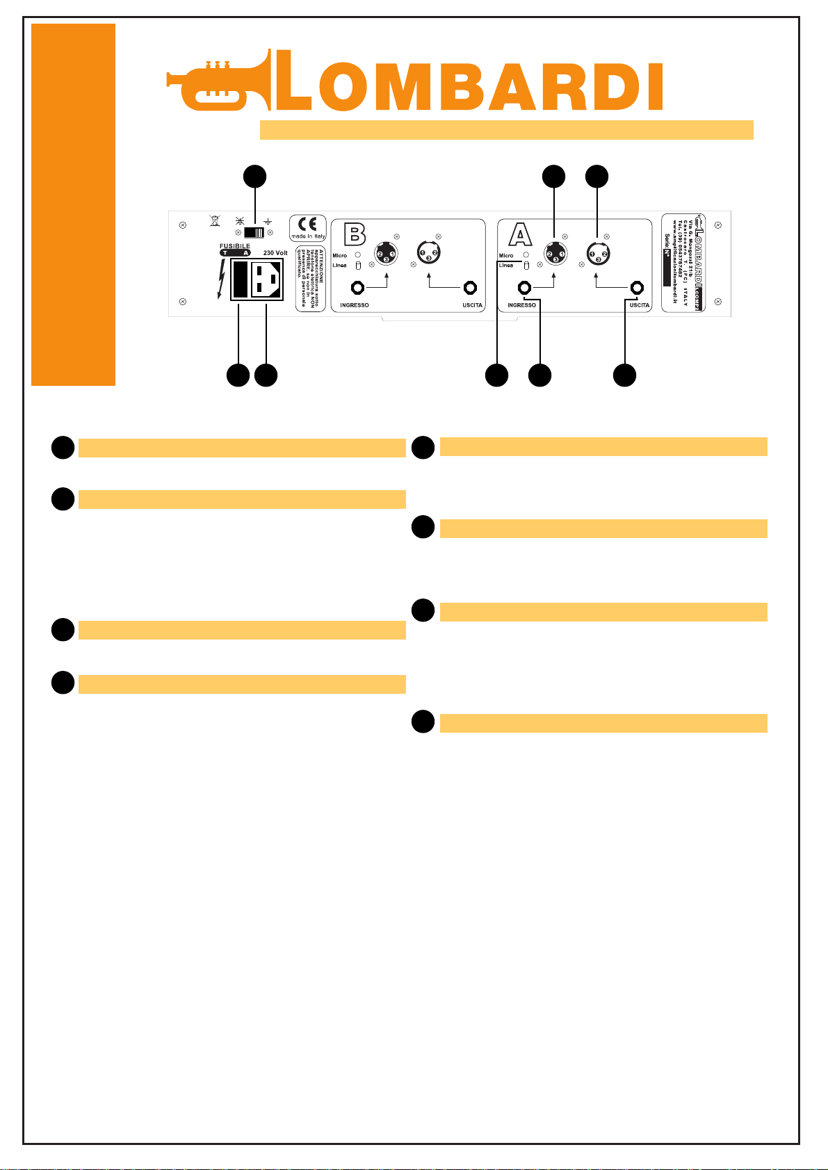
There are 4 holes in front panel for rack
mounting. The space within a rack is 2 units.
mounting RACK
Potentiometer to adjust in increments of
compression ratio, the numerical scale of
reference shows the different compression
ratios possible.
RATIO (rapporto)
The green LED (switched "bypass" down)
indicates the channel is excluded (bypass),
then the input signal is unchanged.
LED BYPASS (escluso)
LCOMP2
Potentiometer to adjust the input volume, the
numerical scale of reference is figured in dB.
INPUT (ingresso)
This switch once and hold (with LED
"excluded" on) indicates that the channel is
excluded (bypass), then the input signal is
unchanged.
switch BYPASS (escluso)
The red LED indicates when the input signal
is too high
LED PEAK (picco)
Potentiometer for adjusting the compression
threshold, the numerical reference scale
ranges from 1 to 10. (increaseing this pot the
treshold is going down)
THRESHOLD (soglia)
Potentiometer to adjust the output volume,
the numerical scale of reference is figured
in dB.
OUTPUT (uscita)
This switch pressed (with LED "control A"
on) indicates that the channelAand channel
B are governed by only channel A.
control in channel "A" (controllo in A)
VU-meters or LED indicating the output level
or the level of compression.
LED VU-meters
This switch lets you decide if the LED VU-
meters show the output level or the level of
compression.
switch output level / level compression
(liv. uscita / liv. compressione)
LED control in channel "A" (controllo in A)
Power switch ON and OFF.
switch on/off (accensione / spegnimento)
This red LED when turned on (switch "control
A" down) indicates that the channel A and
channel B are governed by only channel A.
1 2
3
713
1
2
3
4
810
9
546
12
11
5
6
7
8
9
10
11
12
13

AMPLIFICAZIONI
description of the rear compressor
www.amplificazionilombardi.it
page 7 of 13
switch for switching the ground insertable.
switch
fuse to protect equipment.
fuse:
220/240V: T 0,315 A
115V: T 0,630 A
FUSE (fusibile)
LCOMP2
VDE Power
Input power
Switch OFF - Micro LED red OFF:
- Line in
- High signal level
- Salt used in Insert, insert monitor, powered
speakers, mixer, etc. ..
Switch ON - Micro LED red ON:
- Mic input
- Low signal level
- Low impedance
- Amplification > 20 dB
- Used in Insert a mic channel, direct
microphone, etc. ..
switch and LED line / mic (linea / micro)
balanced input jack 6,3mm
1 ground - 2 signal - 3 phase
input jack 6,3mm
balanced input XLR femmina
1 ground - 2 signal - 3 phase
input XLR (cannon)
balanced output XLR maschio
1 ground - 2 signal - 3 phase
balanced of transformer output
output XLR (cannon)
balanced output jack 6,3mm
1 ground - 2 signal - 3 phase
balanced of transformer output
uscita jack 6,3mm
1
2
1
2
3
4
FUSE
3 5
5
6
7
8
5 84
6 7

AMPLIFICAZIONI
www.amplificazionilombardi.it
page 8 of 13
LCOMP2
XLR
male
1
2
3
jack
stereo
3
2
1
XLR
male
1
2
3
jack
stereo
3
2
1
XLR
female 1
2
3
INPUT
balance
channel A
jack
stereo 3
2
1
mic / line
input
volume threshold
switch to
control in "A"
XLR
female 1
2
3
jack
stereo 3
2
1
channel B OUTPUT
channel A or channels together
switch
mic / line
switch
ratio
output
volume
ratio
threshold
input
volume
balance
INPUT
channel B
OUTPUT
control
compressor
output
transformer
control
compressor
output
transformer

AMPLIFICAZIONI
Monitoring the level of compression and limiting
CHANNEL A
- Switch the instrument on “ liv. Uscita ” (output level)
- Set the radio switch “ Rapporto ” on 8:1
- Set the Threshold “ Soglia “ to 0
- Set the “ Ingresso “ (input) level to the maximum value
- The “ Controllo in A “ switch(Control in A) has to be disconnected
- Verify that the mic/line button on the rear pannel, is positioned to
"linea" (line)
- With a sine wave generator give a signal (sine wawe, 2KHz freq ,
250mV intensivity) into the input circuit of the channel
- Adjust the "uscita" level (output) on the yellow LED (0dB)
- Using the "soglia" control (threshold) to bring the signal down to
-1dB
- Adjust the "uscita" control (output) and brindg the signal to 0 dB
- Increase the signal generator up to 2,5 V (equal to +20dB)
- check that the LED meter light up to +1,5 dB
- If necessary adjust the trimmer located inside into the main
boardsigned R24 (channel A) until the meter indicate +1,5db
- Then move the "rapporto" switch (ratio) on 12:1 and 20:1 and
verify that the signal value is displayed amounted to +1 dB (with
12:1) and 0 dB (with 20:1); work on the same trimmer to reach
this level
CHANNEL B
Same mode of channel A through the trimmer initialed R 124
calibration
www.amplificazionilombardi.it
LCOMP2
page 9 of 13
Input Circuit
instrument calibration
The device has a level indicator LED meter.
In the rest position (no signal) with the switch set to "Liv. Compressione",
the Led bar is lit up at 0 db (yellow LED).
If this doesn't occur, it is possibile to calibrate the instrument using two
trimmers located inside the unit into the main board (R28 for channel
A, R128 for channel B).
Adjust the trimmer until you get 0db (yellow led lit up).
R24
R124
R128R28

AMPLIFICAZIONI
www.amplificazionilombardi.it
page 10 of 13
LCOMP2
In the rear panel of the compressor are located input and
output connection for each channel.
input channel A:
XLR (Cannon) male
jack 6.3 mm female
both connector are balanced and parallel connected
1 ground - 2 signal - 3 phase
input channel B:
XLR (Cannon) male
jack 6.3 mm female
both connector are balanced and parallel connected
1 ground - 2 signal - 3 phase
Output Channel A:
XLR (Cannon) female
jack 6.3 mm female
both connector are balanced and parallel connected
with an output transformer
1 ground - 2 signal - 3 phase
Output Channel B:
XLR (Cannon) female
jack 6.3 mm female
both connector are balanced and parallel connected
with an output transformer
1 ground - 2 signal - 3 phase
inputs and connections

AMPLIFICAZIONI
inputs connection use
www.amplificazionilombardi.it
page 11 of 13
input A
or
input B
outputs connection use
LCOMP2
output A
or
output B
mixer
mixer
mixer
mixer
amplifier
amplifier
balanced
signal
unbalanced
signal
balanced
signal
unbalanced
signal
JACK stereo/
XLR:
1-3 ground
2 signal
JACK mono:
1 ground
2 signal
JACK stereo/
XLR:
1 ground
2 signal
3 phase mic
mic
JACK stereo/
XLR:
1-3 ground
2 ignal
JACK mono:
1 ground
JACK stereo/
XLR:
1 ground
2 signal
3 phase

AMPLIFICAZIONI
Cabinet size in mm [inches]
www.amplificazionilombardi.it
front
page 12 of 13
rear
side
LCOMP2
480 [18,9]
442 [17,4]
87 [3,43]87 [3,43]
365 [14,37]
380 [14,96]
87 [3,43]
FUSE

AMPLIFICAZIONI
This device complies with European directives regarding
electromagnetic compatibility (EMC) 89/336/EEC as amended
by Directives 92/31/EC and 93/68/EC and the low voltage directive
(LVD) 73/23/EC as amended Directives 93/68/EC.
This device complies with European Directive 2002/95/EC and
subsequent amendments concerning the restriction of certain
hazardous substances in the production of electrical and electronic
equipment.
Under the WEEE Directive 2002/96/EC and its amendment
2003/108/EC this equip ment is marked with the symbol of the
crossed out wheelie bin. "INFORMATION TO USERS: Under
Article 13 of Legislative Decree no.151 July 25, 2005-
Implementation of Directives 2002/95/EC and 2002/96/EC, relating
to the use of hazardous substances in electrical and electronic,
as well as waste disposal.
The waste bin symbol indicates that the product at the end of its
useful life, must be separated from other waste. You must bring
the equipment to come to suitable separate collection of waste
electrical and electronic equipment, or return
the retailer when purchasing new equivalent appliance, the ratio
of one to one. Proper waste collection to start following the
treatment and environmentally compatible disposal contributes
in preventing possible adverse environmental effects
and health and promotes the reuse and recycling materials that
make up the equipment.
Illegal disposal of the product by the user includes the application
of administrative sanctions provided for in Legislative Decree no.
22/1997.
compliance with European Community
www.amplificazionilombardi.it
LCOMP2
made in Italy
Table of contents
Popular Compressor manuals by other brands

Indel B
Indel B TB16AM Instructions for use

Panasonic
Panasonic Matsushita DD57C94GBU6 Specification sheet

Ingersoll-Rand
Ingersoll-Rand P185WIR Operating, Maintenance & Parts Manual

Rothenberger
Rothenberger ROPULS Instructions for use

Kooper
Kooper 2196438 User instructions

QSP
QSP DB-8000-XL operating instructions

ALDI
ALDI WorkZone WZK 183 user manual

Ingersoll-Rand
Ingersoll-Rand IR2PS Operation and maintenance

Woodstar
Woodstar cb 50 Translation from the original instruction manual

American Eagle
American Eagle SRS-65 owner's manual

Quincy
Quincy QR-25 Series instruction manual

Gude
Gude 225/08/24 Translation of the original instructions