Ampt Ampt-CU User manual

Manual
AmptCommunicationsUnit
InstallationManual
57070008‐120141110


Copyright2014AMPT,LLC3
InformationandDisclaimer
Copyright 2014 AMPT, LLC. All rights reserved.
No part of this document may be reproduced, retransmitted, or copied in any form without the
expressed and written permission of Ampt.
Ampt makes no representations, expressed or implied, that with respect to this documentation
or any of the equipment and/or software it may describe, including (with no limitation) any
implied warranties of utility, merchantability, or fitness for any particular purpose. All such
warranties are expressly disclaimed. Ampt shall not be liable for any indirect, incidental, or
consequential damages under any circumstances. (The exclusion of implied warranties may
not apply in all cases under some statutes, and thus the above exclusion may not apply.)
The following specifications are subject to change without notice, even though every attempt
has been made to make this document complete, accurate and up-to-date. Readers are
cautioned, however, that Ampt reserves the right to make changes without notice and shall not
be responsible for any damages, including indirect, incidental or consequential damages,
caused by reliance on the material presented, including, but not limited to, omissions,
typographical errors, arithmetical errors or listing errors in the content material.
Ampt LLC
4850 Innovation Drive
Fort Collins, Colorado 80525
Tel 970-372-6950
www.ampt.com

4
ImportantSafetyInformation
Warnings
A warning identifies a hazard to equipment or personnel. It calls attention to a procedure or
practice, which, if not correctly performed, could result in damage to or destruction of part or
all of the Ampt equipment and/or other equipment connected to the Ampt equipment or
personal injury.
The following boxes are used to alert you to important safety information.
Warning:
Indicatesahazardoussituationwhich,ifnotavoided,couldresultindeathorseriousinjury.
Caution:
Indicatesahazardoussituationwhich,ifnotavoided,couldresultinminorormoderate
injury.
Notice:
Indicatesasituationthatcanresultinpropertydamageifnotavoided.
Note:
Thissymbolaccompaniesnotesthatcallattentiontosupplementaryinformationthatyou
shouldknowandusetoensureoptimaloperationoftheAmptsystem.

Copyright2014AMPT,LLC5
TableofContents
InformationandDisclaimer.............................................................................................................3
ImportantSafetyInformation..........................................................................................................4
Warnings..............................................................................................................................................................4
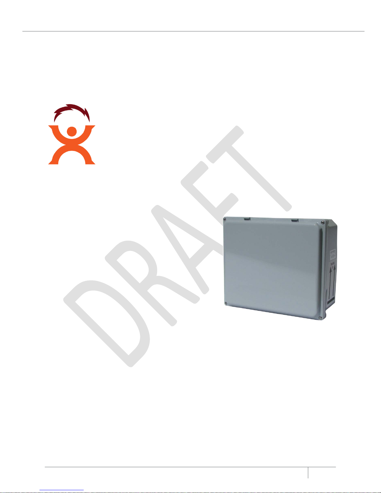
Chapter1:Introduction...........................................................................................................7
GeneralDescription.........................................................................................................................7
Specifications...................................................................................................................................8
ModbusRegisterMap......................................................................................................................9
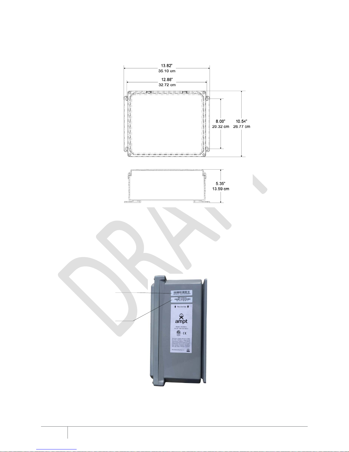
DimensionalDrawing.....................................................................................................................10
PhysicalOverview..........................................................................................................................10
Labels.................................................................................................................................................................10
Internal...............................................................................................................................................................11
UnderstandingtheStatusLEDs......................................................................................................12
Chapter2:InstallingtheAmpt‐CU........................................................................................13
InstallingtheEthernetCableFeed‐through....................................................................................14
MountingtheEnclosure.................................................................................................................16
ConnectingPoweroverEthernet...................................................................................................17
ConfiguringtheAmpt‐CUNetworkSettings...................................................................................18
RestoringFactoryDefaults.............................................................................................................19
Appendix...............................................................................................................................21
Compliance....................................................................................................................................21
FCCCompliance..................................................................................................................................................21


Chapter 2: Installing the Ampt-CU
Copyright2014AMPT,LLC.7
Chapter1:
Introduction
GeneralDescription
The Ampt communications unit (Ampt-CU) provides
wireless two-way communication with every Ampt
converter
The Ampt-CU links to your SCADA or monitoring
system via Modbus to provide highly accurate and
synchronous data. This solution eliminates the need
for smart combiners which lowers costs.
With Ampt communication, system designers,
operators, owners, and financiers gain a level of
transparency and predictability unmatched by
conventional monitoring solutions.
This improved system planning and decision-making capability lowers PV project risk and
increases return on investment.

8
Specifications
SystemLayout
PVblocksize Upto3200 kWpDC
AmptconvertersperAmpt‐CUUpto2000
Exampleoflayout 125stringsx16modules/string =2000Amptconverters
Maximumradiocommunications
operatingrange200mradius
DataCommunications
InterfacewithdatamonitoringsystemModbus/TCP
ConnectionwithdatamonitoringEthernet10/100Base
T
InterfacewithAmptconvertersTwo‐waywireless
Resolution
MeasurementaccuracyAmperage:±0.25%
Reportingrate,typical5minutes,2000converters
Localdatastorage45 dayrollingbuffer
Electrical
PowersupplyPoweroverEthernet(PoE)
PoweroverEthernet(PoE)Class0,802.3afModesAandB,802.3atType1(RJ‐45connector)
Mechanical
EnclosureIP‐66
Dimensions13.82”x10.54”x5.35”
(35.10 cmx26.77cmx13.59cm)
Weight5.6lbs(2.5kg)
Ambienttemperature,operating‐40
°
Fto+185
°
F(‐40
°
Cto+85
°
C)
General
ComplianceFCCPart15,classB
IEC60950‐1,61000‐6‐1,61000‐6‐3

Chapter 2: Installing the Ampt-CU
Copyright2014AMPT,LLC.9
ModbusRegisterMap
Ampt StringViewrecords use the SunSpec protocol for device ID and variable record
length, enabling site-specific operation. The SunSpec Common Model precedes the map
below. Contact Ampt or one of our monitoring partners for more information.
Start
offset
SizeNameType R/W Description
11IDUint16 RAmptSunSpecVendorCode64050
21LUint16 RVariablenumberof16bitregisterstofollow:
12+N*16
FixedBlock(15
)
31DCA_SFInt16 RCurrentscalefactor
42Reserve
d
‐‐
61DBWh_SFInt16 REnergyscalefactor
71Reserve
d
‐‐
81NUint16 RNumberofstrings
96Reserve
d
‐‐
Registerblocksforstringdatafollow.Repeatblockforeachstring.Twostringsareshownasanexample.
151StringIDInt16 RThestringnumber.
162Reserve
d
‐ ‐
182StringdatatimestampUint32 RTheUTCtimestampofthemeasurements.
201OutDCA Int16 RStringoutputcurrentinmA
216Reserve
d
‐ ‐
272DCWhUint32 RDailyintegratedstringoutputenergy
292Reserve
d
‐ ‐
311StringIDInt16 RThestringnumber.
322Reserve
d
‐‐
342StringdatatimestampUint32 RTheUTCtimestampofthemeasurements.
361OutDCA Int16 RStringoutputcurrentinmA
376Reserve
d
‐‐
432DCWhUint32 RDailyintegratedstringoutputenergy
452Reserve
d
‐‐
Repeatblockforadditionalstrings

10
DimensionalDrawing
Figure1:Ampt‐CUdimensionaldrawing
PhysicalOverview
Labels
Figure2:Serialnumber,modelnumber,andMACaddresslabels
Serialandmodel
numberlabel
MACaddresslabel

Chapter 2: Installing the Ampt-CU
Copyright2014AMPT,LLC.11
Internal
Figure3:Interfacepanel
ComponentDescription
EthernetportRJ‐45connectorforPoweroverEthernet(PoE)andEthernetcommunication.
RS‐485portReservedforengineeringuse
TerminationswitchReservedforengineeringuse.
ResetbuttonPressingthisbuttonforcestheAmpt‐CUtoreboot.
RestorebuttonThisbuttonrestoresthenetworksettingsandpasswordbacktotheirfactorydefault
values.SeeRestoringFactoryDefaultsonpage19formoredetail.
PowerLEDThisgreenLEDisoncontinuously whentheinputvoltageis abovetheminimum
threshold.
ComLEDThisLEDdisplaysbootstatus.
FaultLEDThisredLEDcommunicatesfaultconditions.
CablelocksRoutetheinputpowerandcommunicationcables throughtheseguides.
Ethernetport
RS‐485portand
Termswitch
Resetbutton
Restorebutton
PowerLED
ComLED
FaultLED
Cablelocks

12
UnderstandingtheStatusLEDs
The Ampt-CU has three status LEDs. When input power is first applied to the Ampt-CU, all
LEDs are on continuously for several seconds. Then the Com LED flashes amber while
software is booting. Once boot up is complete and the Ampt-CU is operating normally, both
the Power and Com LEDs are on solid green.
NameStateDescription
PowerContinuousGreenInput powersupplyvoltageexceedsthe minimumthreshold.
ComFlashingAmberSoftwareisbootingup.
ContinuousGreenBootprocessiscomplete.
FaultContinuousRedWhenthisLEDisonsolidred afterthebootupprocess,afaultcondition
hasbeendetected.Cycletheinputpower.IfthisLEDisstillonafterthe
ComLEDfinishesflashing(duringthebootprocess),thencontactAmpt
support.

Chapter 2: Installing the Ampt-CU
Copyright2014AMPT,LLC.13
Chapter2:
InstallingtheAmpt‐CU
This chapter addresses the following topics:
Installing the Ethernet Cable Feed-through
Mounting the Enclosure
Connecting Power Over Ethernet
Configuring the Field Computer Network Settings
Restoring Factory Defaults

14
InstallingtheEthernetCableFeed‐through
A liquid-tight wire grip is recommended for the Ethernet cable feed-through. The markings on
the bottom of the unit show where to make a hole for the wire grip.
Figure4:Bottomviewofthecommunicationunit
1. Make sure the communication unit is not powered up.
2. Use a drill or punch to create a hole for the wire grip within the marked area.
Notice:
Drillingoutsideofthedesignatedareamaydamageinternalelectronic
components.
Figure5:Drillholeforthewiregripwithinthemarkedarea
Installliquid‐tight
wiregripinthisarea

Chapter 2: Installing the Ampt-CU
Copyright2014AMPT,LLC.
15
3. Install your wire grip. An example is shown below.
Figure6:Exampleofaninstalledliquid‐tightwiregrip

16
MountingtheEnclosure
Connect the hardware as shown in the figure below, or using a similar method, to mount the
Ampt-CU enclosure.
Figure7:MountinghardwareforAmpt‐CU
Note:
The1‐5/8”washer(number5above)isrecommendedforstrutandunevenmounting
surfaces.
Note:
IfaverticalpoleisusedbehindtheUnistrut,itshouldbeplacednearthehorizontalcenter
oftheAmpt‐CU.
IDDescription
1 4 each ¼-20 x 1.25” 18-8 SS Hex Head Cap Screw (McMaster Carr 92240A544 or
equivalent)
2 4 each ¼ STD split lock washer 18-8 SS (Grainger 1NY97 or equivalent)
3 4 each ¼ STD flat washer 18-8 SS (Grainger 1NU48 or equivalent)
4 1 each Ampt-CU
5 4 each 1 hole washer, flat plate fitting (1-5/8” series) Unistrut P1062 EG or
equivalent (McMaster Carr 3133T11 or equivalent)
6 2 each Unistrut or Kindorf 1-5/8” x 13/16” x 16” galvanized slotted channel
7 4 each ¼-20 strut spring nut, galvanized (McMaster Carr 3259T17or equivalent)

Chapter 2: Installing the Ampt-CU
Copyright2014AMPT,LLC.17
ConnectingPoweroverEthernet
You will need to use a PoE injector that meets the requirements in the Specifications section
on page 8. The diagram below illustrates the basic installation of a PoE injector; however, be
sure to follow the installation instructions that comes with your PoE device.
Caution:
LivevoltagesmaybepresentonthePoEcables.
Figure8:GenericPoweroverEthernet(PoE)connectiondiagram–followtheinstructionsforyourdevice
1. Route the Ethernet cable through the feed-through and cable locks. An example is
shown below.
Figure9:Ethernetcableroutingandconnection
2. Connect the cable to the Ethernet port.
3. Twist the ends of the cable locks together to hold the cable in place.
Note:
Keepwiresoutoftheantennaareaasnotedonthepanel.

18
ConfiguringtheAmpt‐CUNetworkSettings
Note:
CompletingthetasksinthissectionshouldbecompletedbyaNetworkAdministrator.
Please note the following:
Default IP address of the field computer is 192.168.1.249
Web interface to configure the field computer is accessed via port 8080
Modbus data is accessed via port 502
To configure the Ampt-CU network settings:
1. Configure the TCP/IP settings of your laptop to:
a. IP Address - 192.168.1.248
b. Netmask - 255.255.255.0
2. Ensure the Ampt-CU is powered up. The Power LED should be on and solid green.
3. Connect your laptop to the field computer using the Ethernet ports of each device. If using
PoE, the PoE injector must be connected between the laptop and the Ampt-CU.
4. Open your web browser and enter the default IP address (http://192.168.1.249:8080/) in
the address bar.
5. Complete the fields on the login page
a. Login: admin
b. Password: password
6. Once logged in, use the menu on the left to:
a. Change your password
b. Configure network settings
c. Set time zone and network time servers
d. Manage the layout file
e. Setup communications
f. Reference the Modbus map
g. View string/inverter currents, voltages, power
h. Download string data in CSV format - new hardware will not have any data
available until it has been online at least a day with a live system.
i. Perform a system test
j. Enable Ampt support access
k. Reboot the system

Chapter 2: Installing the Ampt-CU
Copyright2014AMPT,LLC.19
Figure10:NetworkSettingsHomeScreen
7. Follow the onscreen directions for each task.
RestoringFactoryDefaults
The network settings and password can be restored to factory default values by pressing and
holding the Restore button during the boot process. If you are using this feature to restore the
password, be sure to record your network settings first. See Configuring the Ampt-CU
Network Settings on page 18 for more details.
To restore the network settings and password:
1. Press the Restart button
2. The LEDs will be on continuously for several seconds.
3. When the Com LED flashes, press and hold the Restore button until the Com and Fault
LEDs alternate flashing.
4. The network settings and password are restored and the unit automatically reboots.

20
This manual suits for next models
1
Table of contents
Popular Conference System manuals by other brands

RADVision
RADVision SCOPIA XT100 Series user guide

Prentke Romich Company
Prentke Romich Company Accent 800 user guide

Philips
Philips LFH9750 - Desktop 9750 Digital Transcriber user manual

Crestron
Crestron UC-M50-T-UPGRD quick start

Sennheiser
Sennheiser ADN C1 quick guide

Poly
Poly G7500 Administrator's guide