Amptec Research 620LK User manual

13231 Rooster Springs Rd.
Austin, TX 78737
amptec.com
AMPTEC RESEARCH
MODEL 620LK OPERATION AND
MAINTENANCE MANUAL

620LK Operation and Maintenance Manual – Rev. J – Updated January 2020
Page 2
13231 Rooster Springs Rd.
Austin, TX 78737
amptec.com
SECTION A: RECEIVING AND INITIAL INSPECTION
A-1 Introduction to AMPTEC 620LK Bonding Milliohmmeter
p. 3
A-2 Unpacking and Inspection
p. 3
A-3 Setup and Preparation for Use
p. 4
SECTION B: 620LK SPECIFICATIONS
B-1 Specifications for AMPTEC 620LK Bonding Milliohmmeter
p. 5
SECTION C: 620LK COMPATIBLE ACCESSORY ITEMS
C-1 Available Accessories and Test Leads
p. 6
SECTION D: OPERATION, FUNCTION, AND USE
D-1 General Use
p. 7
D-2 Front Panel
p. 7
D-2.1 Test Leads and Chassis Ground Connector
p. 7
D-2.2 Connections and 4 Wire Kelvin Information
p. 8
D-2.3 Main Power Switch
p. 8
D-2.4 Display and Backlight
p. 9
D-2.5 Resistance Range
p. 9
D-2.6 Low Battery Display Indicator
p. 9
D-2.7 Autolock Feature Information
p. 9
D-3 620LK Padded Carrying Case Photo and Information
p. 11
D-4 Detailed Use Description
p. 11
SECTION E: MAINTENANCE, REPAIR, AND CALIBRATION
E-1 General Maintenance, Repair, Calibration Information
p. 13
E-2 Returning the 620LK to AMPTEC for Maintenance, Repair, and Calibration
p. 13
E-3 Circuit Board Operation Overview
p. 13
E-4 Block Diagram and Circuit Description
p. 14
E-5 Principle of Operation
p. 14
E-6 Troubleshooting and Diagnostic Testing
p. 14
E-6.1 Current Source PCB Diagnostic Test Routine
p. 15
E-6.2 DVM PCB Diagnostic Test Routine
p. 15
E-7 620LK Calibration Adjustment Procedure
p. 15
E-7.1 Recommended Calibration Standards
p. 16
E-8 PCB Removal from Case
p. 16
E-9 Battery Compartment Design and Description
p. 17
E-9.1 Battery Replacement
p. 17
SECTION F: SAFETY APPROVALS AND CLASSIFICATIONS
F-1 UL-913 Intrinsically Safe Certification
p. 18
F-2 MIL. STD. 810 MTD. 511 Certification
p. 18
SECTION G: REVISION HISTORY AND MANUAL NOTES
G-1 Manual Revision History
p. 19
G-2 Manual Notes
p. 19
TABLE OF CONTENTS

620LK Operation and Maintenance Manual – Rev. J – Updated January 2020
Page 3
13231 Rooster Springs Rd.
Austin, TX 78737
amptec.com
SECTION A: RECEIVING AND INITIAL INSPECTION
A-1 Introduction to AMPTEC 620LK Bonding Milliohmmeter
Originally designed at the request of Lockheed Martin’s engineering team, the AMPTEC
620LK Bonding Milliohmmeter has become the standard in its industry, being used in
aircraft hangars across the globe. The 620LK meter provides extremely safe and
reliable resistance testing on explosive or volatile devices at all times. Our various
safety board approvals (found in section F on page 18) demonstrate our dedication to
making quality products that are safe to use in a variety of atmospheres and
environments.
The AMPTEC 620LK Bonding Milliohmmeter is UL-913 approved as an intrinsically safe
apparatus for use in Class 1, Division 1, Groups A, B, C, and D locations for ambient
temperatures from -20° C to 50° C (T3 zones). The AMPTEC 620LK meter is also MIL.
STD. 810 MTD. 511 approved for use in explosive and volatile atmospheres.
Devices/processes that the 620LK meter can be used for include, but are not limited to:
Electrical chassis ground connections and continuity determination(s) on
electrical subsystems used in general purpose aircraft, helicopters, fighter jets,
UAVs, drones, missiles, etc.
Continuity determinations on fuses, electrical cable connections, heavy duty
metal to metal connections
Bonding measurements for metal to metal connections
Featuring an all metal case with a separate F.O.D. resistant battery compartment, the
AMPTEC 620LK meter has been specifically designed to keep ease of use and
reliability in mind. When it comes to safety, the 620LK meter has failsafe output circuitry
pioneered by AMPTEC to ensure that test current levels do not exceed the specified
failsafe current, even in worst-case component failure situations.
We’re extremely proud of the engineering and quality that goes into each and every one
of our products we’ve created over the past 20 years. We hope you enjoy working with
our 620LK meter and encourage you to contact us if you have any questions or
comments. Thank you for your business!
A-2 Unpacking and Inspection
Should the box you receive your product in be damaged upon its arrival, notify AMPTEC
and the shipping carrier immediately. If your 620LK meter appears damaged, the
carrier’s agent should authorize repairs before the unit is returned to our facility.
If the unit fails to operate or meet performance specifications (listed in section B on
page 5) notify the carrier’s agent and AMPTEC immediately. Retain the shipping
container for the carrier’s inspection.
Do not, under any circumstance, return equipment to any of AMPTEC’s facilities or
sales offices without first obtaining an RMA number (see section E-2 on page 13) from

620LK Operation and Maintenance Manual – Rev. J – Updated January 2020
Page 4
13231 Rooster Springs Rd.
Austin, TX 78737
amptec.com
an AMPTEC staff member. We must obtain your full contact information in order to
properly coordinate the repair and return of the AMPTEC meter.
A-3 Setup for Preparation and Use
The following quick-step guide can be taken to power up and use the AMPTEC 620LK
meter:
1) The meter may be set up to operate as soon as the power is turned on, which
can be accomplished by pressing and holding down the power switch for 2
seconds.
2) Connect the unit’s chassis ground panel jack on the front panel to a local earth or
ground connection.
3) Check the product’s display for a low battery indication. If the product has a low
battery, the display will say “LO BAT”. To see instructions on battery
replacement, see section E-9.1 on page 17.
4) Perform a visual test lead integrity check. It is recommended that the user
perform a basic visual inspection of their test lead set to confirm there is no
damage to any portion of the set.
5) Perform a multimeter continuity test of your test lead set. To do so, ensure all
four wires are isolated from each other, and then connect each pin to its
corresponding opposite pin. Many multimeters will simply beep to indicate that
the leads you are testing are operational.
For a more detailed instructional information on how to use the 620LK meter, see
section D-4 on page 11.
The 620LK meter may be used in any area where the environment does not exceed the
specifications listed in section B on page 5. When possible, avoid exposing the meter to
extremes of temperature, which will affect accuracy and shorten battery life. One should
become familiar with the basic test lead usage and the autolock feature described in
detail in this manual in Section D-2.4 on page 9 in order to properly use the unit.

620LK Operation and Maintenance Manual – Rev. J – Updated January 2020
Page 5
13231 Rooster Springs Rd.
Austin, TX 78737
amptec.com
SECTION B: 620LK SPECIFICATIONS
B-1 Specifications for AMPTEC 620LK Bonding Milliohmmeter
Resistance Range/Resolution/Accuracy:
Calibration: It is recommended that the product is calibrated in 1 year intervals. See
section E-7 on page 15 for calibration instructions.
Dimensions: 7.69” W x 7.56” D x 3” H.
Hazardous Use Locations: Unit is independently UL-913 approved for use in Class 1,
Division 1, Groups A, B, C, and D locations from -20° C to 50° C, as well as MIL. STD.
810 MTD. 511 approved for use in explosive and volatile fuel atmospheres.
Instrument Display: Display is 20,000 counts, 4 ½ digit liquid crystal display with a
back light that indicates autolock. See section D-2.7 on page 9 for additional information
about the autolock feature.
Low Battery Indication: Display shows “LO BAT”.
Measurement Update Rate: Appox. 3 readings per second.
Open Circuit Current Source Compliance Voltage: ~5.0 VDC
Over-Range Indication: Display shows “1 - - - -” and “>>>OR”.
Power: Disposable AA alkaline batteries inside separate chemical and F.O.D. resistant
metal battery box. 4 batteries power the unit, and are 1.5 VDC AA alkaline type Duracell
MN1500. Do not mix battery brands and always replace all batteries at same time. See
section E-9.1 on page 17 for instructions on battery changing.
Temperature Range: Unit can operate from -20° C to 40° C at rated accuracy. Unit can
be stored from -20° C to 70° C.
RANGE
200 mΩ
2 Ω
NOMINAL CURRENT
100 mA
100 mA
RESOLUTION
0.01 mΩ
0.1 mΩ
ACCURACY
± 0.05% of reading
± 0.05% of reading

620LK Operation and Maintenance Manual – Rev. J – Updated January 2020
Page 6
13231 Rooster Springs Rd.
Austin, TX 78737
amptec.com
SECTION C: 620LK COMPATIBLE ACCESSORY ITEMS
C-1 Available Accessories and Test Leads*
620LK Product Packages:
620LK COMMERCIAL AIR PKG: Includes meter, case (630-100), and
probes (630-406S)
620LK LM PKG: Includes meter, case (630-100), leads (630-405S), leads
(630-406S), and spare set of spiked tips (OP-PT-SK)
620LK Meter Accessories:
630-100: Padded F.O.D. resistant case
620LK Test Leads and Probes:
600-PG: 5’ dual pistol grip probes
600-PROC: 5’ compass probe and dual point clamp
600-PROX2: 4’ Dual compass style probes
600-401C: 5’ twin single point current clamps & two voltage probes
630-300: 4’ Kelvin clip lead set
630-304: 4’ 4-Wire banana jack test lead set
630-304G: 4’ 4-Wire banana jack test lead set with ground
630-305: 4’ Twin single banana jack lead set
630-401: 4’ Single point handheld Kelvin probes
630-405K: 10’ heavy duty spiked Kelvin probes
630-405S: 10’ heavy duty spear Kelvin probes
630-406S: 5’ heavy duty spear Kelvin probes
630-407P: 10’ and 5’ heavy duty spiked probes w/ spare tips
630-408J: 10’ heavy duty Kelvin clamp test lead set
KIT8268: Set of 600-401C probes, 600-PROC probes, 600-PG probes,
600-PROX2 probes, and 630-401 probes in pelican case
AMPTEC is also well-versed in making custom accessories and lead/probe sets.
Contact us for any custom requirement you may have to see if AMPTEC can provide
you with a solution.
*For pricing information on our packages, accessories, and lead/probe sets, please
contact AMPTEC. Please note that the above list may change over time, as we update
our price list on an annual basis. Contact AMPTEC to receive the most current list of
620LK compatible accessory items.

620LK Operation and Maintenance Manual – Rev. J – Updated January 2020
Page 7
13231 Rooster Springs Rd.
Austin, TX 78737
amptec.com
SECTION D: OPERATION, FUNCTION, AND USE
D-1 General Use
The AMPTEC 620LK is a milliohmmeter designed to safely measure low level DC
resistance from 0.01 to 1999.9 mΩ. The 620LK meter uses internal solid state voltage
reference(s) that permit the product to be used immediately after the unit has been
turned on (temperature range limits permitting). If you flip the carrying case lid
completely open, and connect the carrying case strap to the unit’s front buckle, the unit
can be carried hands free.
To use the 620LK meter to make a resistance measurement, first connect the desired
measurement leads to the Trident connector on the front panel of the meter. Place the
measurement leads across the unknown resistance value that needs to be measured.
At this point, the 620LK meter should start updating the LCD screen once an electrical
connection has been made. After approximately 3 seconds, the meter will produce a
beeping sound, and the backlight will turn on to illuminate the LCD screen. If the
measurement leads are removed from the component that was being measured, the
meter will hold the resistance reading on the screen. The 620LK meter will resume
measuring resistance once the measurement leads sense a new applied resistance
value, or by pressing the “Auto Measure Reset” button.
If you have any other general use questions, please contact AMPTEC.
D-2 Front Panel
The below sub-sections, D-2.1 through D-2.7, provide information on the features,
design, and uses of the 620LK meter’s front panel. The below photo also shows the
details of the 620LK’s front panel.
D-2.1 Test Leads and Chassis Ground Connections
The AMPTEC 620LK meter test lead connection uses a 4 terminal-in connector on its
front panel, as seen in the diagram on the next page.
The unit’s front panel chassis ground panel jack (which also accepts an external banana
jack) is wired to its all metal case, metal front panel, rear panel, battery compartment,

620LK Operation and Maintenance Manual – Rev. J – Updated January 2020
Page 8
13231 Rooster Springs Rd.
Austin, TX 78737
amptec.com
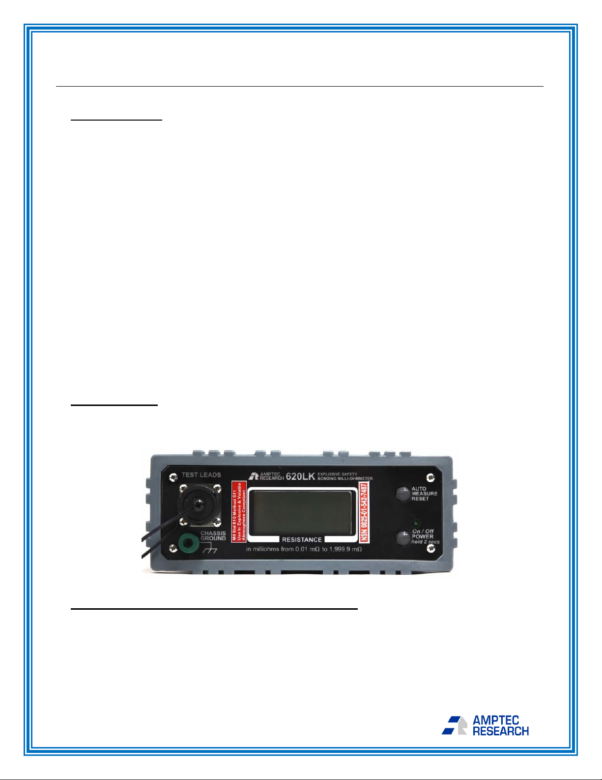
and “pin G” of the test lead connector (see
diagram on right). The unit’s chassis ground can
also be plugged into an earth ground connection
(for example, at the test site to preclude any static
voltages from building up, if desired). To prevent
damaging the gold pins and sockets, only use
AMPTEC test leads that are model 620LK
compatible. When using AMPTEC test leads or
probes, the notched connector end plugs directly
into the single access notched main connector.
Turn the connector collar clockwise until you feel
the click of the mating connector.
D-2.2 Alternate Connections and 4-Wire Kelvin Information
The AMPTEC 620LK meter is
compatible with most AMPTEC 630
series accessories. 620LK compatible
test lead/probes use a Trident
connector on the front panel as the
main connection for lead/probe sets.
The diagram on the right also provides
insight on how the 620LK operates.
The Trident connection provides the
same pin socket arrangement, 4-Wire
current high/low, and voltage sense high/low routed to the end of the leads, and the 4-
Wire Kelvin wires then terminate in a variety of configurations depending upon the
accessory. The 620LK keyed access connector also makes it virtually impossible during
normal operation to incorrectly connect lead/probe sets.
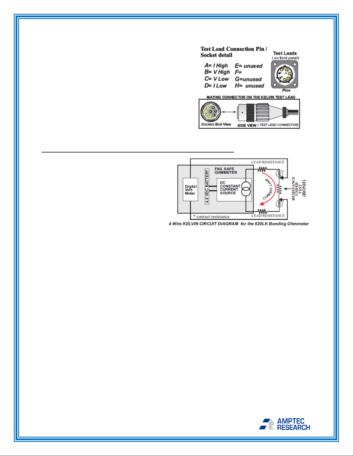
The 620LK meter measures DC resistance with a 4-Wire Kelvin, or 4 terminal ohms,
technique. Fundamentally, the 4-Wire Kelvin resistance method avoids measurement
errors induced from the resistance of the test lead/probes and the contact resistance of
the lead/probes to the device under test. Two of the wires, current high and current low,
pass through the bond resistance under test in a current loop as part of a constant
current source of 100 mA. It doesn’t matter if the current loop is longer or if there is
some contact resistance with the connection under test, because the constant current
source’s compliance voltage works to maintain 100 mA flowing in the loop. The other 2
wires, voltage high and voltage low, sense the voltage drop across the resistance under
test. The voltage measurement is high impedance. Meaning, virtually no current is
drawn in either voltage sense lead wire.
In conclusion, with 4-Wire Kelvin measurements, long distance test leads do not create
a measurement error as long as you have enough compliance voltage remaining in the
constant current loop. If test resistance is too high for the range, the meter will flash
“1 - - - -” and “>>>OR” to indicate the meter is over range.

620LK Operation and Maintenance Manual – Rev. J – Updated January 2020
Page 9
13231 Rooster Springs Rd.
Austin, TX 78737
amptec.com
D-2.3 Main Power Switch
To turn the unit on, the unit’s main power switch must be pressed for 2 seconds. This
momentary hold down routine was designed to prevent accidental power on while the
product is in its carrying case. When the power switch is first pressed and held, the
instrument’s LCD display should light up, as well as a small LED on the front panel,
indicating that the unit is now on. If the switch is pressed again, the unit will turn off. The
main power switch is covered with a silicon rubber boot to provide added water/dust
resistance. Under the rubber boot, there is a rubber o-ring for added weather
resistance.
The 620LK meter is set to automatically turn itself off after 5 minutes of no use in order
to preserve battery life. Contact AMPTEC if you would like to have this feature
deactivated.
D-2.4 Display and Backlight
The 620LK’s display backlight is yellow in color, and will light up when the unit is
powered on. As the 620LK’s display is LCD (liquid crystal display) and high quality, the
display itself should have a life lasting many years. Should the display become
damaged or stop operating properly, it can be replaced at an AMPTEC facility.
The unit’s autolock feature turns the meter’s backlight on and will freeze the reading
unless the “AUTO MEASURE RESET” button on the front panel is pressed or the meter
senses probe continuity is still established. Additionally, the display backlight is off while
the measurement portion of its cycle is active.
D-2.5 Resistance Range
The 620LK can make measurements from 0.00 to 1999.9 mΩ.
The meter starts in Auto Range, but pressing the “AUTO
MEASURE RESET” button when the meter’s backlight is not on
allows the user to cycle through the Auto, 200 mΩ, and 2 Ω
ranges.
If a measurement is made that results in the unit being over-
range, the display will indicate this with “>>> OR” and “1 - - - -“.
D-2.6 Low Battery Indicator
If the unit is running low on battery, the display will indicate this by showing “LO BAT” in
the top left corner. See section E-9.1 on page 17 for information on how to change the
instrument’s batteries.
D-2.7 Autolock Feature Information
The 620LK meter has a built-in autolock feature, in which the unit senses continuity was
established, and automatically samples readings and locks on the most accurate
resistance measurement.

620LK Operation and Maintenance Manual – Rev. J – Updated January 2020
Page 10
13231 Rooster Springs Rd.
Austin, TX 78737
amptec.com
This autolock feature within the meter works by taking 16 resistance measurements in
the positive polarity and averaging them. Another 16 resistance measurements are then
taken in the negative polarity and averaged. The two averaged values from the positive
and negative polarities are then averaged together to produce the final autolocked
measurement, which is the reading displayed while the backlight is on.
To assist the user, the meter produces an audible beeping indicator along with the lit
backlight once an autolock measurement has been found. This beeping allows the user
to focus on the placement of the measurement leads, instead of on the meter’s display.
The autolock feature also enables the measurement to reset automatically if continuity
is sensed or front panel button “AUTO MEASURE RESET” is pressed. The display’s
backlight will turn off while the measurement portion of its cycle is active, and light up
when the instrument has locked on a measurement.

620LK Operation and Maintenance Manual – Rev. J – Updated January 2020
Page 11
13231 Rooster Springs Rd.
Austin, TX 78737
amptec.com
D-3 Carrying Case Photo and Information
The 620LK can be carried and
operated easily hands free. Using
the straps on the case, you can hang
the meter over your head and neck,
leaving your hands free to use a
lead/probe set to make a
measurement. The below itemized
list references figure 2.
Item A: ITT Cannon/Trident Kelvin
test lead Connector with waterproof
dust cap.
Item B: Chassis ground connector.
Chassis is connected completely to
case. Case is all alluminum,
including front and rear panels.
Item C: 4 ½ Digit LCD Display
with “LO BAT” and “<<<OR”
shown as an example.
Item D: AUTO MEASURE
RESET BUTTON. Press and
hold to reset a measurement
that has been locked.
Item E: Power On/Off Switch
with LED. Press and hold for 2
seconds to power the unit on.
The display backlight and a
small LED on the front panel will
indicate the power is on.
D-4 Detailed Use Description
The below provides a detailed description on the best way to use the 620LK meter for
bond measurements.
Starting out, the Kelvin probes should not be touching a conductor - the meter is open
circuit and the display indicates "1- - - -". Find a clean area on both the part you need to
test (no paint or coating), and the metal chassis of your test item. Pointed probes work
best on aluminum parts as this type of material often has a thin coating (aluminum
oxide) that is a non-conductor. Press and hold each probe with a steady hand, and note
it is only necessary to push the probe tip springs in about half way. Do not move the
FIGURE 1
FIGURE 2

620LK Operation and Maintenance Manual – Rev. J – Updated January 2020
Page 12
13231 Rooster Springs Rd.
Austin, TX 78737
amptec.com
probes for 3 to 5 seconds. The meter has 2 resistance ranges (a 199.99 mΩrange and
a 1.9999 Ωrange) and needs a little settling time to automatically determine which
range is best before displaying the calculated bond value.
When the display backlight comes on, the meter has made a bond measurement. The
probes may be removed while the unit's backlight is on, as the unit’s autolock feature
freezes the reading. The backlit frozen measurement will stay frozen until you either
press the "AUTO MEASURE RESET" button or press the test probes against a
conductor (meaning continuity is sensed). When ready to make another measurement,
simply place the probes back on the test items, and the meter will automatically make
another measurement. See section D-2.7 on page 9 for more information regarding the
autolock feature.
The user may use the unit's carrying case with padded straps to securely hold the bond
meter around their neck, while their hands hold the Kelvin probes and make bond
measurements. Repetitive measurements assure a good bond measurement; it may be
necessary to hold the probes down for 2 consecutive displayed measurement cycles to
avoid any timing issue of probe placement in the unit's measurement cycle, and
assuring the first initial settling in on the proper range. Bond measurement is almost
always a pass/fail test to determine if the bond is better than a given resistance level.

620LK Operation and Maintenance Manual – Rev. J – Updated January 2020
Page 13
13231 Rooster Springs Rd.
Austin, TX 78737
amptec.com
SECTION E: MAINTENANCE, REPAIR, AND CALIBRATION
E-1 General Maintenance, Repair, and Calibration Information
The AMPTEC 620LK meter was designed with the intent of using high quality, strong,
and reliable components both internally and externally. As a result, the unit is extremely
reliable and rarely requires repair. Should the unit require maintenance or repair that
cannot be performed by the end user, we recommend sending the product to AMPTEC
RESEARCH’s facility to perform this service. Malfunctions can sometimes be the result
of bad test lead/connection wiring, wrong connections, misinterpretation of
specifications, low battery levels, or a misunderstanding of how to use the product.
The below sections will provide information on sending your unit to AMPTEC for repair,
as well as how the user can perform some maintenance, troubleshooting, and
calibration techniques on their own.
E-2 Returning the 620LK to AMPTEC for Maintenance, Repair, and Calibration
AMPTEC RESEARCH has been proudly providing product support for all of our
equipment for the past 20 years. Part of this support is offering maintenance, repair, and
calibrations for our instrumentation. Our staff is highly trained across our product lines
and is capable of fixing nearly any issue your instrument may have. AMPTEC maintains
one sole facility for both the manufacturing and repair of its products:
AMPTEC RESEARCH CORP.
14101 Hwy 290. W.
Bldg. 2000A
Austin, TX, USA 78737
Should you have a product that you would like to be sent in for maintenance, repair, or
calibration, it can be sent to the address above.Before sending in a product to our
facility, you must contact a member of our staff and receive an RMA #. We can be
reached via email at info@amptec.com or phone at 512-858-4045. The purpose
process of this is so that we can obtain your full contact information and properly
coordinate the return of the AMPTEC meter.
Once we have received your meter, we will diagnose the issue for free and provide you
with pricing information. If diagnosing the problem requires one of our technicians to
open the product in order to reach the internal circuitry, a calibration fee will be required
for us to send the product back to you. This is because we have a plant-wide policy that
all instrumentation must be calibrated before leaving our facility – it would be unethical
to allow out of ordnance products to be sent to an end user.
E-3 Circuit Board Operation Overview
There is one internal printed circuit board (PCB) that performs the digital ohmmeter
resistance measurement. The AMPTEC 620LK meter uses a constant current source
circuit and DVM circuitry all on one PCB. When the constant current source is combined
with the digital voltmeter circuit, the result is a stable DC resistance measurement.

620LK Operation and Maintenance Manual – Rev. J – Updated January 2020
Page 14
13231 Rooster Springs Rd.
Austin, TX 78737
amptec.com
The DVM PCB’s electronics use a high input impedance voltage sense circuit. This
circuit draws very little current, while measuring the DC voltage drop across the
resistance under test. The AMPTEC 620LK main PCB slides in easily, by following
grooves on the inside of the aluminum case.
Schematics for the 620LK’s PCB are protected and strictly confidential, regardless of
the circumstance.
E-4 Block Diagram and Circuit Description
E-5 Principle of Operation
Using Ohm's Law (V/I =R), the AMPTEC 620LK Bond Meter first outputs constant DC
current through a given test resistance, then measures the voltage drop across it while
scaling its display as resistance. The 1.9999 Ωrange outputs a constant 100 mA DC
level of test current. On a 1 Ω resistor, the 620LK 100mA output should get a 100mV
drop (0.10V/0.10A). For DVM scaling on the 2 Ωrange, voltage drop is amplified using a
x10 (for range scaling), hence a 10 mV drop becomes 100mV. This DVM input is
displayed as 100.00 m Ωon a 0.100 Ωstd. During the cycle, the meter changes
polarity, samples again, and displays the average reading of both polarities.
E-6 PCB Troubleshooting and Diagnostic Testing
If the malfunction is a faulty part, the repair of the 620LK meter can be attained by
replacing the proper internal PCB. There are no serviceable components (much of the
components are surface mount) on the 620LK PCBs, so it is often a case of entire PCB
replacement. See section E-2 on page 13 for more information about sending your
product in for repair.
The following sub-sections will facilitate the diagnosis as to whether the AMPTEC
620LK current source circuitry or digital voltmeter circuitry needs repair or replacement.
These steps should only be performed by authorized personnel who are trained to do
so.

620LK Operation and Maintenance Manual – Rev. J – Updated January 2020
Page 15
13231 Rooster Springs Rd.
Austin, TX 78737
amptec.com
E-6.1 Current Source PCB Diagnostic Test Routine
The following steps can help determine if the current source circuitry is faulty:
1) Put output leads across a 0.100 Ω resistance standard (0.005% or better).
2) Measure the voltage drop with a DC Voltmeter. It should be 0.0100V.
If the above test proves untrue, then the current source circuitry is possibly faulty, and
may need replacing. See section E-2 on page 13 for more information about sending
your product in for repair.
E-6.2 Digital Voltmeter (DVM) PCB Test Routine
The following steps can help determine if the DVM circuitry is faulty:
1) Short the output leads.
2) Check for a reading of 0.000.
3) Put the output leads across a 0.100 Ω resistance standard.
4) The display should read 100.00 mΩ (± 10 counts depending on the resistor’s
accuracy).
If the above test proves untrue, then the DVM circuitry is possibly faulty, and may need
replacing. See section E-2 on page 13 for more information about sending your product
in for repair.
E-7 620LK Calibration Procedure
The 620LK’s rear panel calibration sticker must be removed to access the two
adjustment potentiometers located on the DVM PCB.Please note that if the tamper-
proof calibration sticker is removed, this voids the product’s calibration and
warranty.
All the meter’s calibration adjustments (via trimpots) are accessed through two holes
located in the upper right area of the rear panel, under the tamper-proof calibration
sticker. The two holes (see diagram below) are for zero and full-scale adjustments. A
set of two hole plugs normally cover the zero and full-scale adjustment holes.

620LK Operation and Maintenance Manual – Rev. J – Updated January 2020
Page 16
13231 Rooster Springs Rd.
Austin, TX 78737
amptec.com
Zero Adjustment: With a precision 0.001 Ω (1.0 mΩ) resistance standard that’s
0.005% or better, connect 4-Wire Kelvin test jacks (630-304) to the AMPTEC 620LK
meter. Through the top far right rear panel hole, adjust the trim-pot (see above diagram
labeled zero) to make the meter read the exact value of the .0 mΩ laboratory standard
resistor (i.e. ~1.00 mΩ value will be displayed). Because of the autolock feature, you will
have to wait 5 to 10 seconds between adjustments and readings for settling and an
updated display of the measurement. The meter will continue to sample and hold, and
then resample as long as it senses any continuity.
Full-scale Adjustment: Next, connect the meter via the 630-304 test leads across a
precision 100 mΩresistance standard which is a 0.005% or better accuracy resistance
standard. Adjust the full-scale pot, using the hole located to the top left of the rear panel
zero pot access hole (see above diagram labeled fullscale), until the display is the
actual value of the 100 mΩresistance standard in milliohms (i.e. 99.97 mΩif the
standard is actually 0.09997 Ωs). Because of the autolock feature, you will have to wait
5 to 10 seconds between readings for settling and an updated display of the
measurement. The meter will continue to sample and hold, and then resample as long
as it senses any continuity.
Finally, connect the meter via the 630-304 test leads across a precision 1.0 Ω
resistance standard which is a 0.005% or better accuracy resistance standard. Allow a
few seconds for settling time. Keep in mind the meter autoranges up to the 2.0 Ω range
when measuring a value above 200 mΩ. Verify the meter is within 5 counts (± .005 Ω)
on a 1.0 Ω standard.
This concludes the adjustment procedure for the AMPTEC 620LK meter.
E-7.1 Recommended Calibration Standards
We recommend using our 630-304 4-Wire banana jack test lead set to calibrate the
620LK meter. If you are interested in purchasing a set of these leads, please contact
AMPTEC.
If you need to purchase resistance standards, we recommend using a reputable
manufacturer and insuring that all standards are N.I.S.T. traceable. AMPTEC currently
uses Ohm-Labs for many of its standards.
AMPTEC has a full-scale calibration laboratory within its manufacturing facility, and has
the full capability to calibrate your product(s) for you. If you are interested in using our
calibration services, please see section E-2 on page 13.
E-8 PCB Removal
Removing the PCB from any of our products is strongly discouraged. If a user is going
to perform the task, they need be authorized and trained. AMPTEC provides a free PCB
replacement for products under warranty, and a small fee for non-warranty products.
Removing the PCB from the 620LK meter will void the product’s warranty and
calibration.

620LK Operation and Maintenance Manual – Rev. J – Updated January 2020
Page 17
13231 Rooster Springs Rd.
Austin, TX 78737
amptec.com
The following procedure can be
performed to remove the PCB from the
620LK meter:
1) Use a Philips screwdriver to
remove the 620LK’s 4 front panel
screws located in the corners.
2) Pull the front panel forward
carefully and slowly.
3) Slide out the display PCB. Use
caution with doing this, as there
are 4 wires (battery supply positive
and negative, and 2 DVM sense
wires) and a single ribbon cable
(going to the display PCB) that
connect the front panel electronics
to DVM PCB circuitry mounted
inside the case.
4) Slide out main PCB.
5) Disconnect all wires and cables
that go to the faulty PCB.
6) Reinstall all wires and cables onto
the new PCB.
7) Follow the calibration procedure in
section E-7 on page 15.
8) Slide the main PCB back in, and
replace the front panel and screws.
E-9 Battery Compartment Design and
Description
The metal battery compartment is
powder coated to make it chemically
resistant to battery leakage, and backed with a water tight rubber based compression
gasket liner. The battery supply wiring insulation is made of extra thick (> 5mm) Teflon
to provide excellent resistance to abrasion. Since the batteries are in a separate
compartment where the operator has no access to the unit’s internal electronics, any
user may replace the batteries as needed and this activity does not interfere with the
unit’s warranty or calibration.
E-9.1 Battery Replacement
To replace the batteries, you must remove the two retaining screws securing the battery
compartment cover plate on the rear panel. In order to be UL-913 compliant, the
batteries must be AA alkaline (1.5 VDC) type Duracell MN1500. Do not mix battery
batches or brands for any reason. Make sure to replace all four batteries at the same
time, and re-secure new batteries with a plastic cable tie or similar fastener.

620LK Operation and Maintenance Manual – Rev. J – Updated January 2020
Page 18
13231 Rooster Springs Rd.
Austin, TX 78737
amptec.com
SECTION F: SAFETY APPROVALS AND CLASSIFICATIONS
F-1 UL-913 Intrinsically Safe Certification
The AMPTEC 620LK meter is independently UL-
913 approved as an intrinsically safe apparatus for
use in Class 1, 2, 3, and 4, Division 1, Groups A, B,
C, and D locations from temperatures -20° C to 50°
C. This certification was gained in 2013, and is
maintained with quarterly inspections by an
independent party.
AMPTEC also follows UL-913’s quality standards
plant-wide, including the adoption of a quality
manual, policies for non-conforming parts, policies
for personnel, and many more.
If you are interested in obtaining a copy of
AMPTEC’s UL-913 certification, please contact our
sales dept.
F-2 MIL. STD. 810 MTD. 511 Certification
The AMPTEC 620LK meter is MIL. STD. 810 MTD.
511 approved for use in explosive and volatile fuel
environments.
If you are interested in obtaining a copy of
AMPTEC’s MIL. STD. 810 MTD. 511 certification
please contact AMPTEC.

620LK Operation and Maintenance Manual – Rev. J – Updated January 2020
Page 19
13231 Rooster Springs Rd.
Austin, TX 78737
amptec.com
SECTION G: REVISION HISTORY AND MANUAL NOTES
G-1 Manual Revision History
The below table details changes made over time to this manual.
Revision Name
Date
Description
Rev. J 01/2020
Revision history table added, manual notes added,
accuracy spec. updated, table of contents updated
G-2 Manual Notes
The below area may be used to write notes and/or any other pertinent information.
____________________________________________________________
____________________________________________________________
____________________________________________________________
____________________________________________________________
____________________________________________________________
____________________________________________________________
____________________________________________________________
____________________________________________________________
____________________________________________________________
____________________________________________________________
____________________________________________________________
____________________________________________________________
____________________________________________________________
____________________________________________________________
____________________________________________________________
____________________________________________________________
____________________________________________________________
____________________________________________________________
____________________________________________________________
____________________________________________________________
Table of contents
Other Amptec Research Measuring Instrument manuals

Amptec Research
Amptec Research 620UK-4 User manual

Amptec Research
Amptec Research 620A-4 Manual

Amptec Research
Amptec Research 601ES Manual

Amptec Research
Amptec Research 620A-4 User manual

Amptec Research
Amptec Research 620UK-B User manual

Amptec Research
Amptec Research 720A User manual

Amptec Research
Amptec Research 620A SERIES User manual

Amptec Research
Amptec Research 620A-4 Manual