AMPTech S User manual

SOFTCLOSE AUTOMATIC
MODEL S
INSTALLATION GUIDE
V. M3 SOC20-MKII FD/AD

Table of contents
2
Specifications 4
Below you will find more detailed information about the supplied
components. 4
Technical data of the Soft Close doors 4
Technical data ens engine for theSoftclose automatic 4
List of the required tools for the installation 5
Please check the scope of delivery of the order before starting the installation.
7
List about the scope of delivery 7
Installation guide 8
Front door 8

Table of contents
3
About this guide
Product
descriptions
All specifications and descriptions of the products in this installation
manual have been verified and tested at the time of writing and are valid
for the respective version mentioned in the manual. We reserve the right
to make modifications and improvements to the products at any time.
Errors and inaccuracies
If you notice any errors or inaccuracies in this installation guide, or if you
notice that some descriptions are not complete, please use the following
We are open to your recommendations and suggestions and will gladly
accept them under the e-mail.
Copyright
This document is protected by copyright and is the intellectual property of
AMP Engineering GmbH. The contents of this manual may not be
modified, duplicated or copied in whole or in part without the express
written consent of AMP Engineering GmbH.
Safety instructions
The softclose automatic system has been designed to allow the doors to close
comfortably and safely. Nevertheless, pay attention to possible warnings on the
display of your on-board computer and do not start the journey under any
circumstances if an error is displayed. If you have any questions or problems with
the Softclose automatic, please contact AMPTech by phone +49 176 64990890 or
by e-mail support@amptech.store.

4
Specifications
Below you will find more detailed information about the supplied components.
Technical data of the Soft Close doors
Softclose
Operating voltage
12 V direct current
Operating current
5 A
Technical data ens engine for theSoftclose automatic
Softclose motor
Operating voltage
12 V direct current
Operating current unloaded
≤1,1 A
Motor speed unloaded
280 - 360 rpm
Locking torque
≥4 Nm
Maximum current
20 A
Transmission ratio
26,4
Acoustic emission
≤60 dB

5
Preparations
To ensure that the installation can be carried out quickly, tools required for
the installation should be provided before starting. The required tools are
listed below.
List of the required tools for the installation
Tool list
Position
Designation
1
Pliers
2
Soft pad (blanket or similar)
4
Scissors
5
Plastic mounting lever
7
Ratchet/Ratchet
8
Socket wrench set / nut
9
Cordless screwdriver
10
Cable ties in large and small
11
Adhesive tape
12
Cutting tool (knife)
13
Torx set
14
Storage box for screws

6
15
Flashlight
16
Insulating tape
17
Rust protection
18
Cable lubricant
19
Alubutyl
💡Tip
A commercially available toolbox contains many of the
tools needed.

Preparations
7
Please check the scope of delivery of the order before starting the
installation.
List about the scope of delivery
Scope of delivery
Position
Designation
1
4 softclose motors
2
4 harnesses
3
2 Y connectors for power supply
4
2 Ground cable black
After checking the scope of delivery and providing the tools, you can
proceed with the installation instructions.

8
Installation guide
Before starting the installation, prepare a storage area for the components
to be removed during the installation. It is also recommended to store
clamps and screws in a labeled container to prevent confusion later.
This installation guide describes the installation of the softclose mechanism
on the two doors on the right-hand side of the vehicle in the direction of
travel. The installation is identical on the right-hand side of the vehicle in the
direction of travel and can therefore be carried out according to the same
instructions.
💡Tip
Start the installation at the passenger door.
Front door
Two T30 screws behind the metal door handle and a 10 mm hexagon
screw behind the handle trim are removed first.
These are each behind a plastic cover, which must be removed
beforehand using a plastic tool.
● The door panel can be levered out manually or with the help of a
plastic tool to the rear, starting from the front upper edge (at the level
of the side mirror).
● Cables connected to the door panel and the Bowden cable for
opening the door must be disconnected from the door panel in the
next step.

9
● 6 T20 screws are removed so that the plastic inner lining can be
dismantled
The speaker is also dismantled by removing 4 screws
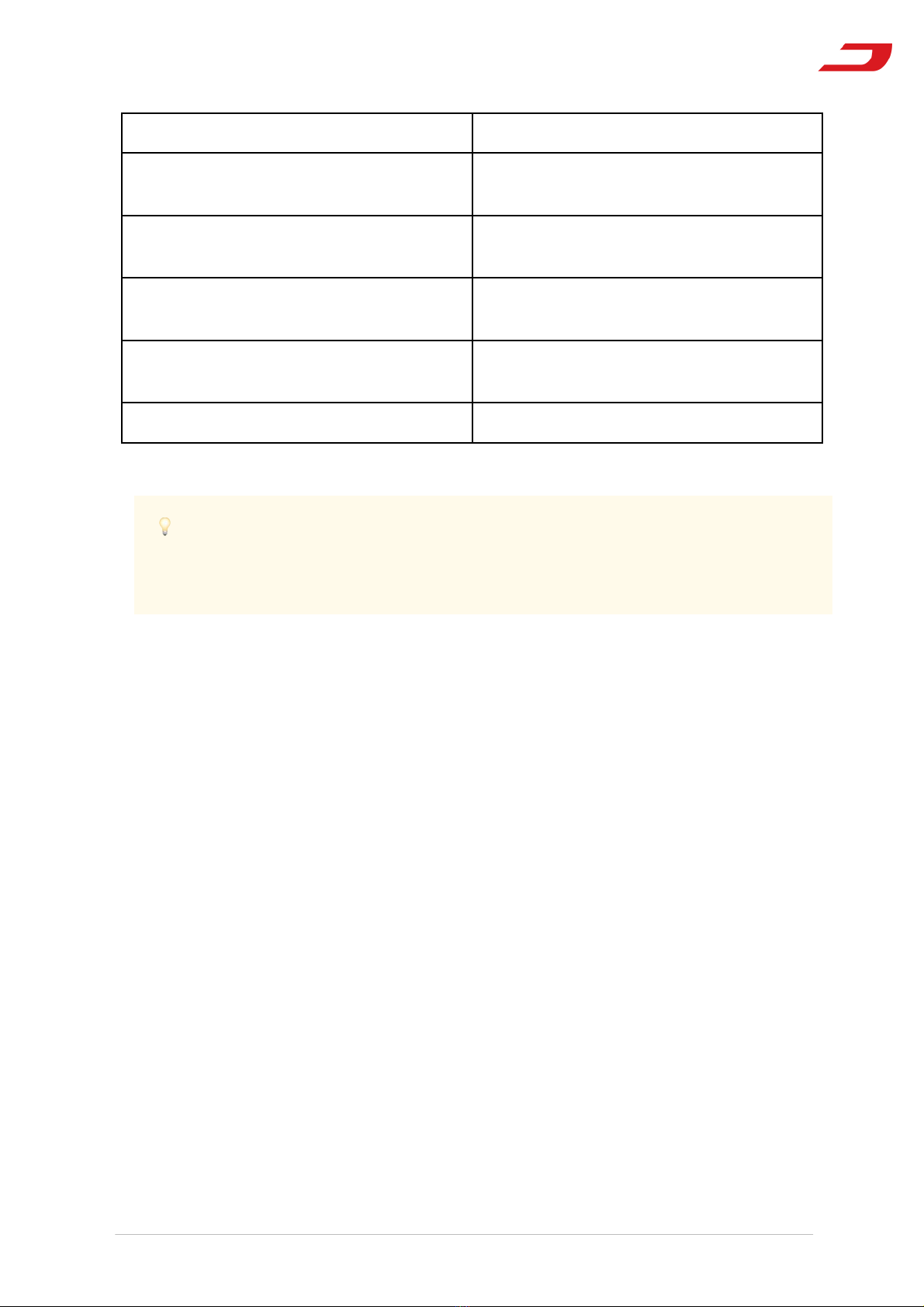
● The next step is to remove 2 T30 screws from the lock unit so that the
lock can be carefully lifted out through the opening behind the
windowpane guide. The plug connected to the lock unit must be
disconnected before lifting it out.
ATTENTION:The window must be fully raised during this step.
● The Bowden cable must be removed from the old lock and connected
to the new lock unit. To do this, loosen the plastic barbs with a slotted
wrench.
The lock unit with yellow Styrofoam is used for the right side of the
vehicle (analogously, unit with blue Styrofoam is for the left side of the
vehicle).
First, the Bowden cable must be attached to this lock.
ATTENTION: The end piece of the Bowden cable must be hooked
behind the lug provided for this purpose in the new lock.
● Attach the plug for the lock unit to the new lock unit
● The new lock unit can now be inserted into the door behind the
windowpane guide. The two T30 screws previously loosened on the
old lock are used to secure the new lock unit.
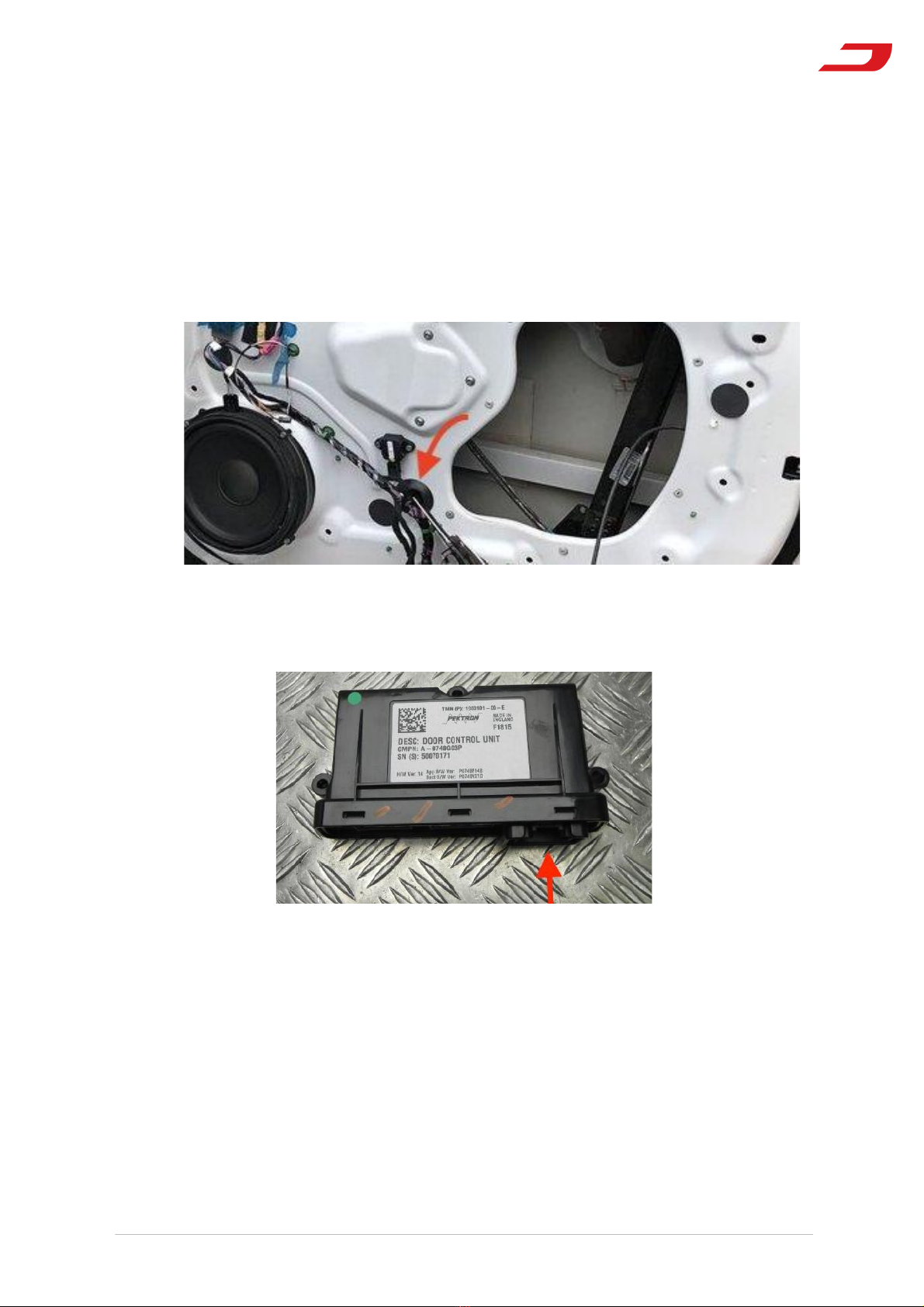
● In the next step, the soft close motor is glued to the door body facing
outwards with the butyl already attached to the motor. Make sure
that the pull cable of the motor is not kinked and leads straight from
the motor to the lock unit.

10
● The cables of the lock should be fixed on the door body facing the
inside of the vehicle so that they do not interfere with the window
when it is lowered. Alubutyl strips can be used for this purpose.
● The cables of the soft close motor should be attached to the door body
facing outwards - Alubutyl can also be used here.
The black and yellow cable of the new unit are to be led out through
the rubber sealing hose from the inside of the door (see picture)
Attach the power supply Y-connector to the bottom of the Tesla
door control unit located on the plastic trim.

11
○ For the next steps, the door sill trim must be removed. This is
secured with clamps and can be pushed out towards the inside
of the vehicle. In this way, access is gained to the cable hose that
connects the vehicle interior with the door. In the next steps, the
power cable is routed out of the door and the ground cable is
routed into the door through this hose.
○ Both the Y-connector (power) and the ground cable have a long
and a short End - For the following steps, make sure that the
correct end is used.
○
The short end of the yellow power cable (from the Y connector) is to be
connected to the yellow power cable of the clamping unit.
1. Subsequently, the long end of the power cable must also be routed
into the vehicle interior. To do this must:
2. The long end of the
cable through an
opening back to the
inside of the door body
(see picture)
Be routed from
inside the door
body to the vehicle
interior via the
door's cable
conduit
Attention: It is recommended to use a retraction aid and cable
lubricant during this step in order not to damage the cables
already present in the cable conduit. The speaker opening
serves as access for this step.

12
○ The black ground
cable is routed to the
connector in the
same way. To do this
must:
○ The short end of the
black ground cable
from the vehicle
interior first through
the cable hose into the interior of the door body and then
through the opening shown in the picture above to the black
plug of the door lock unit.
○ Attention: Also for this step it is recommended to use a
retraction aid and cable lubricant in order not to damage the
cables already present in the cable conduit. The speaker
opening serves as access for this step.
● The forked cable lug of the black ground cable can be fixed under any
body bolt in the interior of the vehicle.

13
System test
After the power and ground cables have been connected to the
clamping unit, a first manual function test can be performed. To do
this, press the latch of the lock with the door open using a plastic tool.
After an initial latching position is reached, the softclose motor pulls
the latch completely closed. The door must then be opened from the
inside. This is done by pulling the Bowden cable. The latch of the lock
is then pressed again and the lock is opened by the outer door handle.
Finally, the window is carefully moved to the lowest and then to the
highest position. Check if there are any collision points between the
window lifting device and the installed cable. If this is the case,
carefully check the above-mentioned steps for fastening the cables
and plugs.
If all tests are successful, the door panel can be removed.
ATTENTION: This test must be performed with each door before
the first closing, otherwise a malfunction or incorrect installation
will not be detected.
Dismantling the front door
● If all function tests have been carried out successfully, the
loudspeaker can be reinstalled.
● The connection of the power plug is located in a waterproof section of
the door. Nevertheless, this must be insulated for safety reasons.
Conventional insulating tape can be used for this purpose.
● Excess cables are to be fixed to the existing cable harnesses with
Velcro or plastic cable ties
● The cable connections with the door panel must be restored
● The end cap of the Bowden cable should be hung in the designated
place of the door handle in the door panel.
Finally, the door panel can be removed.
Rear door
The locking latches of the rear doors of the Tesla Model S are located in the
C-pillar of the vehicle, unlike the front doors. For this reason, access via the
rear is required to replace the lock with the AMPTech locking unit.

14
The T20 screw of the plastic side trim piece of the tailgate is removed
so that the trim piece can then be removed.
The overlying panel, fixed with clamps, is removed by levering it
towards the vehicle interior.
● For the next steps, the rear seat must be folded down.
Then remove the belt guide's adjacent pastiche cover. This is
fastened with 4 metal clips and must be levered in the direction of
the interior.

15
The plastic holder underneath is fixed with two pin clamps. To
remove them, first pry out the pins with plastic tools and then
remove the clamp mount.
The side support of the seat must be removed by pulling it at the
upper end in the direction of travel and then lifting it out upwards.
● Now the paneling can be pushed to the side so that the cover of the
hatch to the lock is visible.
● Remove the black oval cover of the hatch to replace the lock unit in
the next step.
In the next step, the 2 T30 screws of the clamping unit are loosened from
the outside so that the lock can be removed.

16
After the lock has been led out through the hatch, the plug and
emergency bowden cable with the associated housing part must be
removed from the lock unit. To remove the bowden cable, loosen two
T8 screws.
● The next step is to install the housing of the emergency hoist in the
new clamping unit. To do this, first insert the hook of the Bowden
cable into the hole provided for this purpose in the new clamping
unit. The housing is then brought into position and fastened using
the two T8 screws.
● The plug for the closing signal must then be plugged in and locked
in place
● The clamping unit is then to be positioned through the hatch in
under the C-pillar and fastened with the two previously loosened
T30s
● The new clamping unit must then be connected to the voltage and
power cable, which has been pulled from the front to the rear.
The soft-close motor of the lock unit is also routed through the hatch
under the C-pillar and positioned behind the lock. To secure this unit, it is
fitted with a butyl strip.

17
System test
Deconstruction of the rear door
● Once all functional tests have been successfully performed,
dismantling can begin.
● The black oval cover of the hatch must be modified with a drill or
milling cutter so that the power cable of the clamping unit can be fed
through it.
● The connection of the power plug of the rear is located in a waterproof
section of the interior. Nevertheless, this must be insulated for safety
reasons. Conventional insulating tape can be used for this purpose.
● Excess cables should be secured to the existing wiring harnesses with
Velcro or plastic cable ties and routed behind the trim and sill panels.
Finally, the door panel can be removed.
The first closing of the door is done carefully and under observation of the
positions of the closing latch on the door and the closing latch in the C-pillar.
If these are not positioned correctly in relation to each other, the latch can
be fine-tuned in a final step.

18
Checklist
After wiring:
● All plugs are connected
● The cables and connectors in the door are tied together with cable
ties and fixed with tape
● The screw on the voltage supply in the driver's compartment is
tightened
● The ground is tapped on the driver's side and passenger side
● The connectors of the ground and power supply are isolated
The clamping unit and the control unit are securely fastened
Attaching the door panel::
● All plugs on the door panels are connected
The clamps of the door panels are all engaged
System test:
● Door opener, window regulator, loudspeaker and door lock are
working
● The windows can be raised and lowered without any problems
● All doors close with the soft close mechanism
The emergency Bowden cable works
Deconstruction:
● All routed cables are located underneath the panels and are not
visible
● All claddings are attached and fastened
Table of contents
Other AMPTech Automobile Accessories manuals
Popular Automobile Accessories manuals by other brands

Whispbar
Whispbar S42W Fitting instructions

Metra Electronics
Metra Electronics 99-5807 installation instructions

RBO
RBO IT FITS RBO1120 product manual

Track Dog Racing
Track Dog Racing TDR-01M111 Quick start quide

Mont Blanc
Mont Blanc RF 25 Fitting instructions

Rugged Radios
Rugged Radios RZR PRO XP Mount installation guide