AMPTech X User manual

AUTOMATIC FRUNK
MODEL X
INSTALLATION GUIDE
V. MX FNK20-MKIV
About this guide 3

Table of contents
2
Specifications 4
Technical data of the lifting arms 4
Technical data of the engine for automatic frunking 4
Preparations 5
List of tools needed for the installation 5
List about the scope of delivery 6
Installation guide 7
Remove cladding 7
Replace lifting arms 8
Modify clamping unit 10
Wiring 13
System test and system settings 17
Checklist 19
Deconstruction 21

3
About this guide
Product
descriptions
All specifications and descriptions of the products in this installation manual
have been verified and tested at the time of writing and are valid for the
respective version mentioned in the manual. We reserve the right to make
modifications and improvements to the products at any time.
Errors and inaccuracies
If you notice any errors or inaccuracies in this installation guide, or if you
notice that some descriptions are not complete, please use the following e-
We are open to your recommendations and suggestions and will gladly
accept them at the email
.
Copyright
This document is protected by copyright and is the intellectual property of
AMP Engineering GmbH. The contents of this manual may not be modified,
reproduced or copied in whole or in part without the express written
consent of AMP Engineering GmbH. Likewise, the commercial use of this
manual is prohibited.
Safety instructions
The automatic frunk control was designed to enable convenient and safe
opening and closing of the front cover (frunk). Nevertheless, as such it does
not replace the visual inspection. Therefore, always check that your frunk is
securely closed before starting a journey. In any case, the safety instructions
marked "🚫CAUTION:..." in these instructions must be observed. In case of
disregard of the safety instructions and resulting damages to the AMPTech
components or even vehicle parts, the warranty claim as well as any liability
for damages or consequential damages expires due to own fault (see GTC's
on www.amptech.store/agb/, V. Liability). If you have any questions or
problems with the Frunkautomatic, please contact AMPTech under the

4
Specifications
Below you will find more detailed information about the supplied components.
Technical data of the lifting arms
Lifting arms
Maximum lift arm length
360 mm
Minimum lifting arm length
112 mm
Highest diameter
32 mm
Maximum operating force
700 N
Operating voltage
12 V DC voltage
Operating current
5 A
Operating temperature
-30° Celsius −85° Celsius
Protection class
Static IP 67, on the move IP 65
Technical data of the engine for automatic frunking
Motor for automatic frunk
Operating voltage
12 V DC voltage
Operating current unloaded
≤1,1 A
Motor speed unloaded
280 - 360 rpm
Locking torque
≥4 Nm
Maximum current
20 A

5
Transmission ratio
26,4
Acoustic emission
≤60 dB
Preparations
To ensure that the installation can be carried out quickly, tools required for
the installation should be provided before starting. The required tools are
listed below.
List of tools needed for the installation
Tool list
Position
Designation
1
Torx T20/T30
2
Needle nose pliers
4
Slotted screwdriver
5
Plastic mounting lever
7
Ratchet/Ratchet
8
Socket wrench set/nut (10mm,
13mm)
9
Cable ties in large and small
10
Adhesive tape
11
Cutting tool
💡Tip
A commercially available toolbox contains many of
the tools you need.

Preparations
6
Please check the scope of delivery of the order before starting the
installation.
List about the scope of delivery
Scope of delivery
Position
Designation
1
2 lifting arms
2
Softclose motor with emergency
release tab
3
Control unit
4
Cable tie
5
Power adapter plug with fuse
6
2 cable harnesses
7
2 adapter plates with ball joints
8
2 screws (hexagon socket)
9
Acoustic signal generator
10
Double-sided adhesive tape (3M)
After checking the scope of delivery and providing the tools, you can
proceed with the installation instructions.

Installation guide
Before proceeding to the removal of the inner lining, it is advisable to expose
storage areas for the parts removed in the course of the installation. In
addition, it is helpful to keep the clamps and screws that are removed
sorted.
Remove cladding
● Remove the four interior trim panels arranged around the front
storage compartment. To do this, pull the panels upwards with a jerk
(Figure 1).
Figure 1: Plastic cladding in the frunk
● Remove the front storage compartment carpet trim by reaching
under the rubber lip and separating the carpet trim from the rubber
lip
● Disconnect the two plugs for the storage compartment lighting and
the plug for the pushbutton. The plugs are locked according to the
barb principle
● Then lift out the carpet lining
● The plastic tray under the fairing is fixed with 20 hexagonal screws
(10mm). Loosen the screws (Figure 2)

Installation guide
8
Figure 2: Screwing of the plastic tray
● Lift out the plastic tray
Replace lifting arms
● Remove the lift arms by levering the locking cotter pin with the
slotted screwdriver and pulling on the respective end of the lift arm
by hand until the lift arm releases at the attachment point (Figure 3)
Figure 3: Loosening the lifting arms
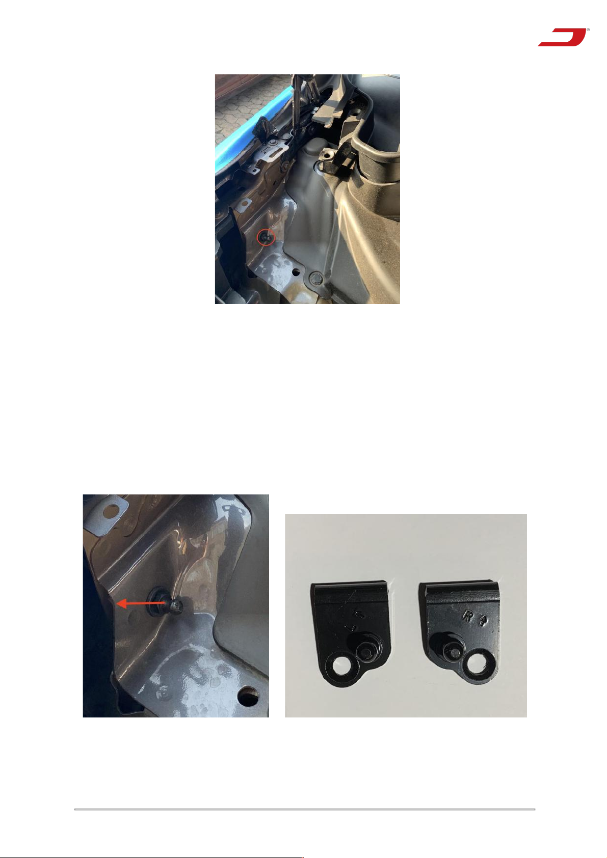
● Loosen the joints at the lower attachment points of the lifting arms
using a socket wrench (13mm) (Figure 4)
Installation guide
9
Figure 4: Lower attachment point
● Use the adapter plates included in the scope of delivery and screw
them to the lower attachment points of the lift arms using the screws
included in the scope of delivery. The adapter plates are marked with
"L" (left) and "R" (right) and refer to the left and right side of the vehicle
in the direction of travel. The arrows on the adapter plates indicate the
corner of the adapter plate that is further up when attached. The
curved part of the adapter plate is guided over the sheet metal edge
marked with the red arrow (Figure 5).
Figure 5: Attaching the adapter plates
Installation guide
10
💡Tip
Loosen one lift arm and attach the new lift arm to
the lower attachment point first. After the second
lift arm has been loosened, press both lift arms
against the joint at the upper attachment point so
that the lift arms engage. A second person should
be used to replace the lifting arms.
● The lifting arms for the automatic frunk are pressed against the ball
of the ball joint with the locking split pin until they engage. A "click"
sound is heard when they engage. The front hood must be held in
position for this if necessary.
● Test with both hands whether the front cover can be moved without
any problems
Modify clamping unit
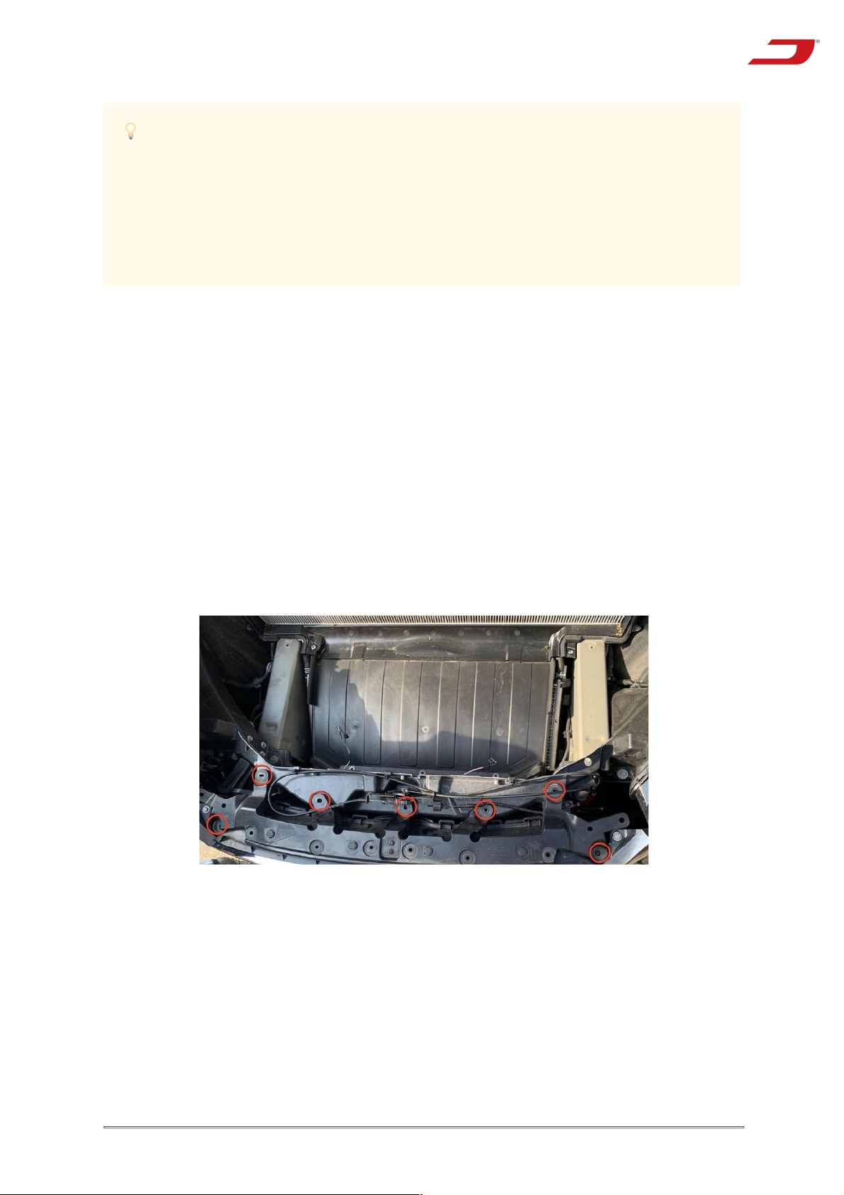
● Loosen the 7 hex head screws (10mm, hex) that secure the plastic
cover above the Tesla emblem (Figure 6)
Figure 6: Screwing of the front plastic cover
● Loosen the two pin clips at the ends of the plastic cover. These are
located underneath the plastic cover (Figure 7)
Table of contents
Other AMPTech Automobile Accessories manuals

Popular Automobile Accessories manuals by other brands


ULTIMATE SPEED
ULTIMATE SPEED 279746 Assembly and Safety Advice

SSV Works
SSV Works DF-F65 manual

ULTIMATE SPEED
ULTIMATE SPEED CARBON Assembly and Safety Advice

Witter
Witter F174 Fitting instructions

WeatherTech
WeatherTech No-Drill installation instructions

TAUBENREUTHER
TAUBENREUTHER 1-336050 Installation instruction