Introduction
These 45 series modules are the same as the original designs, and contain all of the original
components.
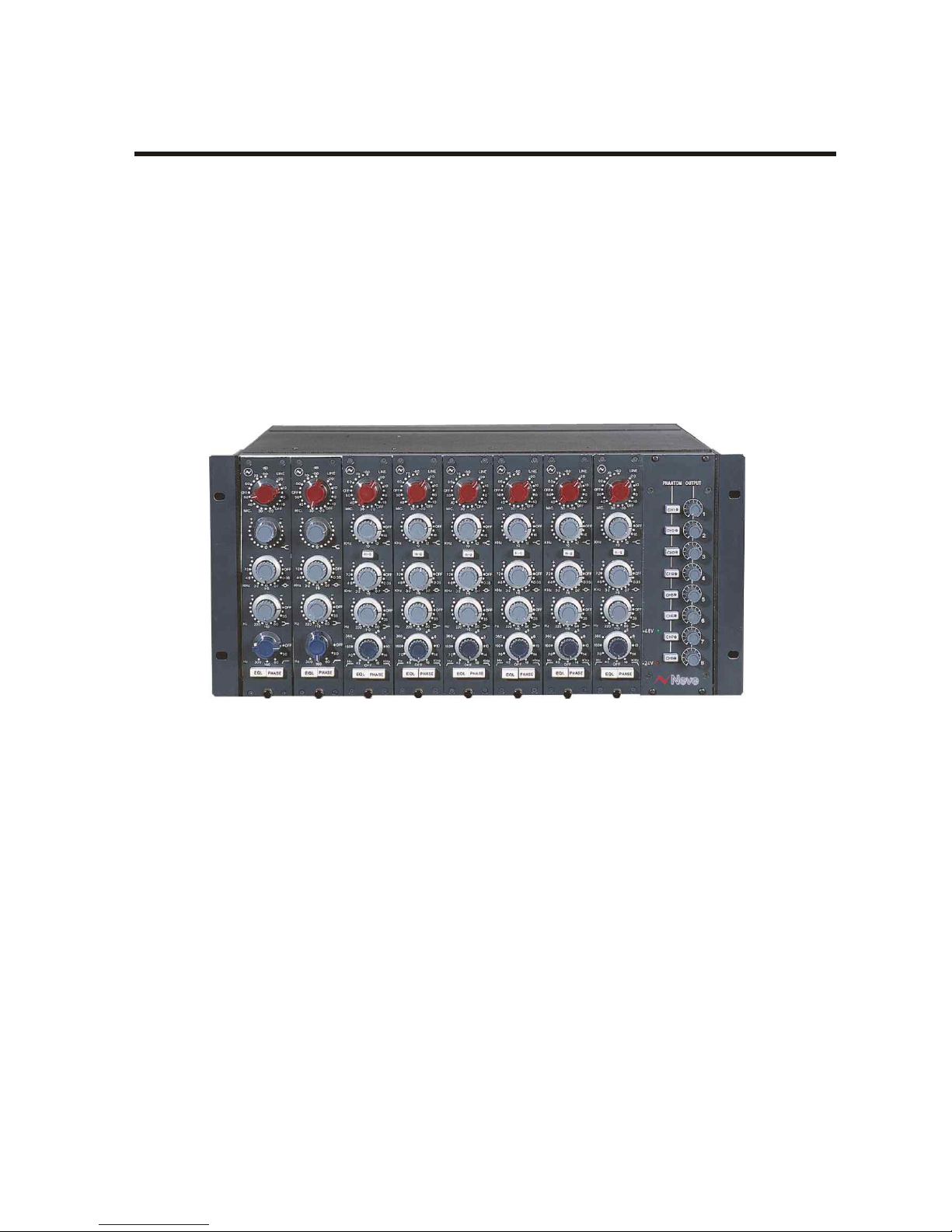
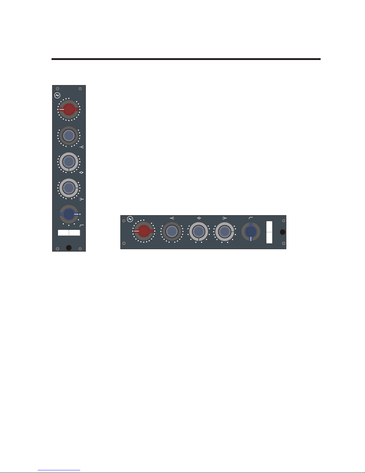
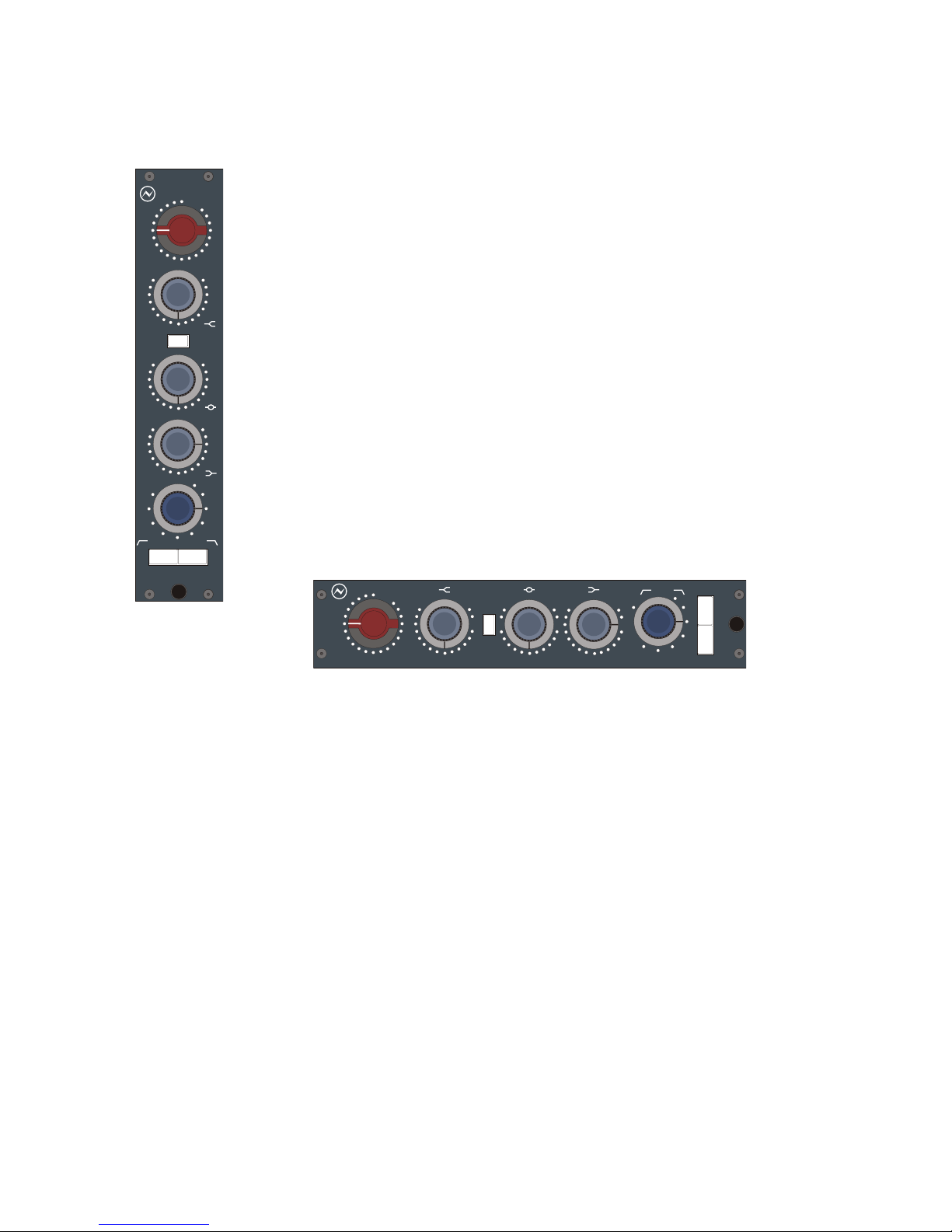
1073 Channel Amplifiers
These very popular sounding mic pre's are considered by many to capture the very essence of the
Neve sound. In manufacture since the early 1970s, the Class A design offers 3 bands of EQ with
one fixed high frequency and a high pass filter.
1084 Channel Amplifiers
Based on the same technology as the 1073s, the 1084s again deliver the unique sound and quality
of Neve. However, the 1084s offer additional features, including 3 switchable EQ bands with cut
and boost, a high Q for presence and low pass/high pass filters.
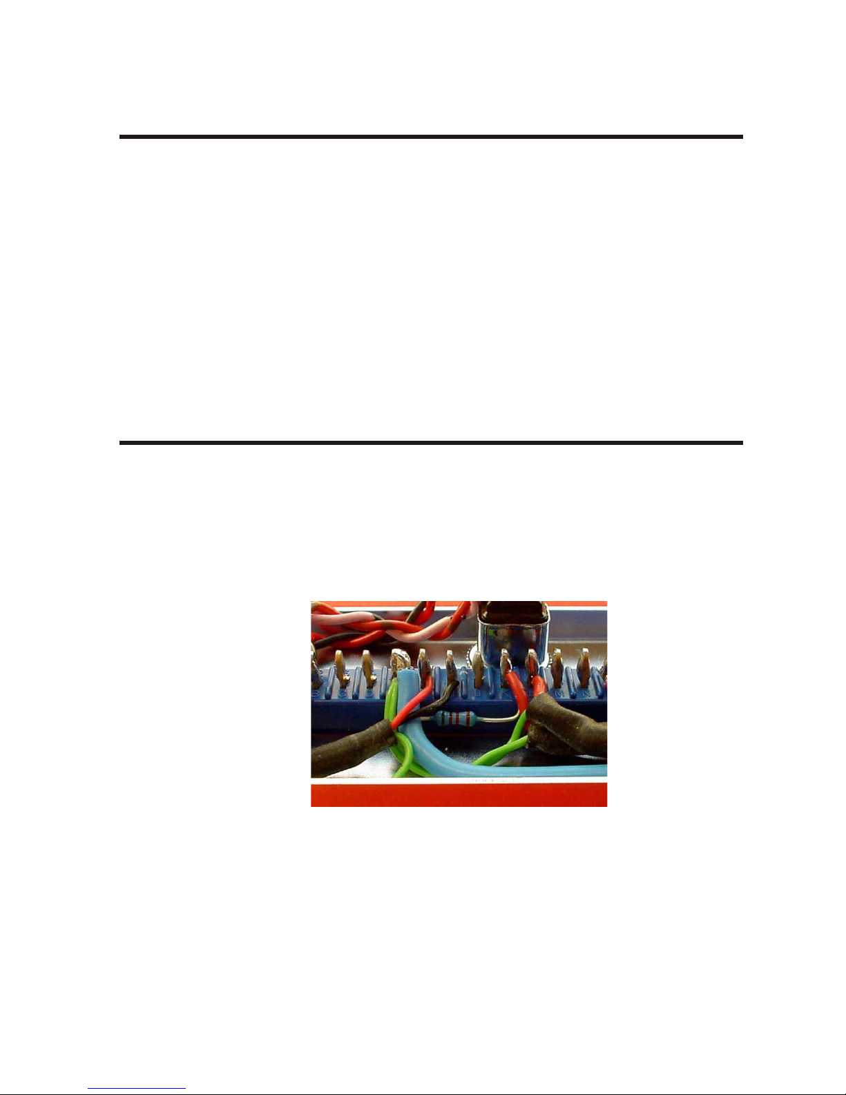
High Pass Filter (resistor modification)
Important Note
The high pass filter in both the 1073 & 1084 modules is a passive design and as such must be
correctly terminated to achieve a maximally flat response.
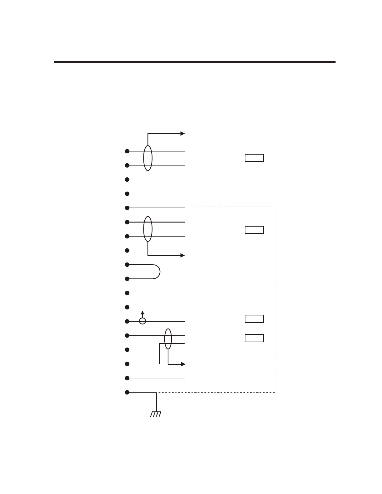
In order to achieve this there is a 5k1 resistor fitted inside the module on the back connector
between pin E (0v) and pin K (fader send) see diagram below:
In situations where the fader connection is not used (most Neve 45 series consoles except
BCM10's) then the resistor remains in place.
In situations where the fader connection is used (BCM10's and AMS Neve 1073/1084 racks)
then the 5k1 resistor should be disconnected and replaced with a fader or potentiometer whose
value is 4k7 / 5k ohms.
-All modules which leave the factory with either a 3U or 5U rack unit will have the 5K1 resistor
removed.
Failure to do so will result in incorrect levels and uneven frequency response.
User Guide Issue 3 Page 1
1073 & 1084 Channel Amplifiers Introduction