manuals.online logo
Brands
  1. Home
  2. •
  3. Brands
  4. •
  5. AMT
  6. •
  7. Water Pump
  8. •
  9. AMT 4292-96 Assembly instructions

AMT 4292-96 Assembly instructions

Specications Information and Repair Parts Manual 4292-96
4292-251-00 1 3/2015
Please read and save this Repair Parts Manual. Read this manual and the General Operating Instructions carefully before attempting to assemble, install, operate
or maintain the product described. Protect yourself and others by observing all safety information. The Safety Instructions are contained in the General Operating
Instructions. Failure to comply with the safety instructions accompanying this product could result in personal injury and/or property damage! Retain instructions
for future reference. AMT reserves the right to discontinue any model or change specications at any time without incurring any obligation.
©2015 AMT Pump Company, A Subsidiary of The Gorman-Rupp Company, All Rights Reserved.
Periodic maintenance and inspection is required on all pumps to ensure proper operation. Unit must be clear of debris and sediment. Inspect for leaks and loose bolts. Failure to do so
voids warranty.
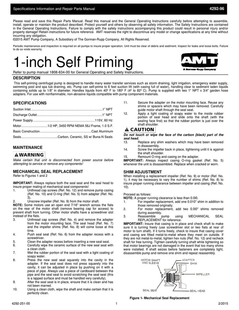
1-inch Self Priming
Refer to pump manual 1808-634-00 for General Operating and Safety Instructions.
SPECIFICATIONS
Suction Inlet…………………………………………………………..1” NPT
Discharge Outlet……………………………………………………..1” NPT
Power Supply……………………………………………..……115V, 60 Hz
Motor………………….…1/2 HP, 3450 RPM NEMA 56J Frame, 1.0 S.F.
Basic Construction…………………………………….……Cast Aluminum
Seals……………………………..Carbon, Ceramic, SS w/ Buna-N Seals
MAINTENANCE
Make certain that unit is disconnected from power source before
attempting to service or remove any components!
MECHANICAL SEAL REPLACEMENT
Refer to Figures 1 and 2
IMPORTANT: Always replace both the seal seat and the seal head to
insure proper mating of mechanical seal components!
1. Unthread cap screws (Ref. No. 12) and remove pump casing (Ref.
No. 10) and O-ring (Ref. No. 5) from adapter (Ref. No. 3).
2. Unscrew impeller (Ref. No. 9) from the motor shaft.
NOTE: Some motors use an open end 7/16” wrench across the ats on the
rear of the motor shaft (remove bearing cap for access) to prevent shaft from
turning. Other motor shafts have a screwdriver slot instead of the ats.
3. Unthread cap screws (Ref. No. 4) and remove the adapter from the
motor mounting face. The seal head (Ref. No. 7) and the impeller
shims (Ref. No. 8) will come loose at this time.
4. Push seal seat (Ref. No. 6) from the adapter recess with a
screwdriver.
5. Clean the adapter recess before inserting a new seal seat.
6. Carefully wipe the ceramic surface of the new seal seat with a
clean cloth.
7. Wet the rubber portion of the seal seat with a light coating of soapy
water.
8. Press the new seal seat squarely into the cavity in the adapter.
If the seal seat does not press squarely into the cavity, it can be
adjusted in place by pushing on it with a piece of pipe. Always
use a piece of cardboard between the pipe and the seal seat to
avoid scratching the seal seat (this is a lapped surface and must be
handled very carefully).
9. After the seal seat is in place, ensure that it is clean and has not
been marred.
10. Using a clean cloth, wipe the shaft and make certain that it is
perfectly clean.
11. Secure the adapter on the motor mounting face. Reuse any shims
or spacers which may have been removed. Carefully guide motor
shaft through the seal seat.
12. Apply a light coating of soapy water to the inside rubber portion of
seal head and slide onto the shaft (with the sealing face rst) so
that the rubber portion is just over the shaft shoulder.
Do not touch or wipe the face of the carbon (black) part of the seal head.
13. Replace any shim washers which may have been removed in
disassembly.
14. Screw the impeller back in place, tightening until it is against the
shaft shoulder.
15. Remount O-ring and casing on the adapter.
IMPORTANT: Always inspect casing O-ring gasket (Ref. No. 5) whenever the
unit is disassembled. Replace when cracked or worn.
DESCRIPTION
This self-priming centrifugal pump is designed to handle many water transfer services such as storm draining, light irrigation, emergency water supply, swimming
pool and spa tub draining, etc. Pump can self-prime to 6 feet suction lift (with casing full of water), handling clear to sediment laden liquids containing solids up to
1/8” in diameter. Handles liquids from 40º F to 180º F (4º to 82º C). Pump is supplied with two 1” NPT x 3/4” garden hose adapters. For use with nonammable,
non-abrasive liquids compatible with pump component materials.
Specications Information and Repair Parts Manual 4292-96
4292-251-00 2 3/2015
SHIM ADJUSTMENT
When installing a replacement impeller (Ref. No. 9) or motor (Ref. No. 1), it may
be necessary to vary the number of shims (Ref. No. 8) to insure proper running
clearance between impeller and casing (Ref. No. 10).
Proceed as follows:
NOTE: A proper running clearance is less than 0.0l0.
1. For impeller replacement, add one 0.010” shim in addition to those
removed originally.
2. For motor replacement, add two 0.0l0” shims removed during
assembly.
3. Reassemble pump using MECHANICAL SEAL REPLACEMENT for
reference.
IMPORTANT: Be sure that casing is in place and check shaft to make sure it
is turning freely (use screwdriver slot or two ats at rear of motor to turn shaft).
If it turns freely, check to ensure that casing cover and casing are tted metal-
to-metal where they meet on outside. If they are not metal-to-metal, tighten hex
nuts (Ref. No. 12) and recheck shaft for free turning. Tighten carefully turning
shaft while tightening so that motor bearings are not damaged in the event that
too many shims were installed. If shaft seizes before fasteners are completely
tight, disassemble pump and remove one shim and repeat reassembly.
1-inch Self Priming Utility Pump
Figure 1 - Mechanical Seal Replacement
Specications Information and Repair Parts Manual 4292-96
4292-251-00 3 3/2015
For Repair Parts contact dealer where pump was purchased.
Please provide following information:
-Model Number
-Serial Number (if any)
Part description and number as shown in parts list
Figure 2 - Repair Parts Illustrations
1-inch Self Priming Utility Pump
Repair Parts List
Ref Part Number for model:
No. Description 4292-96 Qty
1 Motor, includes Cord 1626-009-00 1
2 Seal Kit - Buna-N (standard) 4292-300-90 1
Seal Kit - Viton (optional) 4292-301-90 1
(includes Ref. Nos. 5, 6, and 7)
3 Adapter 2218-004-01 1
4 Hex Head Cap Screw * 4
5 O-Ring Gasket - Buna-N (standard) 2104-004-00 1
O-Ring Gasket - Viton (optional) 2105-023-00 1
6&7 Shaft Seal Assembly - Buna-N (standard) 1640-161-90 1
Shaft Seal Assembly - Viton (optional) 1640-161-91 1
8 Impeller Shim Package 1657-000-90 1
9 Impeller 2104-024-09 1
10 Casing 2218-005-01 1
11 Drain Plug * 1
12 Hex Head Cap Screw * 6
13 Cord Set 1639-077-00 1
14 1” NPT x 3/4” Garden Hose Adapter 1696-073-00 1
(*) Standard hardware item, available locally.

Other AMT Water Pump manuals

AMT 5150-96 Assembly instructions

AMT

AMT 5150-96 Assembly instructions

AMT 4410-95 Assembly instructions

AMT

AMT 4410-95 Assembly instructions

AMT 3890-99 Assembly instructions

AMT

AMT 3890-99 Assembly instructions

AMT Crono S-PID 30 Operating instructions

AMT

AMT Crono S-PID 30 Operating instructions

AMT 4660-99 Assembly instructions

AMT

AMT 4660-99 Assembly instructions

AMT 4230-97 Assembly instructions

AMT

AMT 4230-97 Assembly instructions

AMT 2827-98 Assembly instructions

AMT

AMT 2827-98 Assembly instructions

AMT Submersible Pump 12V DC Series Owner's manual

AMT

AMT Submersible Pump 12V DC Series Owner's manual

AMT 489 Series Assembly instructions

AMT

AMT 489 Series Assembly instructions

AMT 3670-94 Assembly instructions

AMT

AMT 3670-94 Assembly instructions

AMT 4292-96 Assembly instructions

AMT

AMT 4292-96 Assembly instructions

AMT 3826-99 Assembly instructions

AMT

AMT 3826-99 Assembly instructions

AMT 2874 Assembly instructions

AMT

AMT 2874 Assembly instructions

AMT 3100-99 Assembly instructions

AMT

AMT 3100-99 Assembly instructions

AMT 316F-95 Assembly instructions

AMT

AMT 316F-95 Assembly instructions

AMT 5585-H6 Assembly instructions

AMT

AMT 5585-H6 Assembly instructions

AMT 3899-98 Assembly instructions

AMT

AMT 3899-98 Assembly instructions

AMT 07ES05C Series Assembly instructions

AMT

AMT 07ES05C Series Assembly instructions

AMT 3160-99 Assembly instructions

AMT

AMT 3160-99 Assembly instructions

AMT 5761-95B Assembly instructions

AMT

AMT 5761-95B Assembly instructions

AMT 4294-98 Assembly instructions

AMT

AMT 4294-98 Assembly instructions

AMT 2827-95 Assembly instructions

AMT

AMT 2827-95 Assembly instructions

AMT 489B-98 Assembly instructions

AMT

AMT 489B-98 Assembly instructions

AMT 4906 Assembly instructions

AMT

AMT 4906 Assembly instructions

Popular Water Pump manuals by other brands

GORMAN-RUPP PUMPS 811/2B3-B Installation, operation, and maintenance manual with parts list

GORMAN-RUPP PUMPS

GORMAN-RUPP PUMPS 811/2B3-B Installation, operation, and maintenance manual with parts list

Baker Hughes Druck PV 62X instruction manual

Baker Hughes

Baker Hughes Druck PV 62X instruction manual

BGS technic 1609 instruction manual

BGS technic

BGS technic 1609 instruction manual

Star HSPJ100 user manual

Star

Star HSPJ100 user manual

Taco 0015e3 instruction sheet

Taco

Taco 0015e3 instruction sheet

Grundfos HYDRO MPC instructions

Grundfos

Grundfos HYDRO MPC instructions

Wacker Neuson PTS 4V Operator's manual

Wacker Neuson

Wacker Neuson PTS 4V Operator's manual

WAGNER Cobra 40-10 Original operating manual

WAGNER

WAGNER Cobra 40-10 Original operating manual

swiftech MCP355 manual

swiftech

swiftech MCP355 manual

Intex Quick-Fil AP634 owner's manual

Intex

Intex Quick-Fil AP634 owner's manual

AL’S GARDEN ART AJP quick start guide

AL’S GARDEN ART

AL’S GARDEN ART AJP quick start guide

SAER Elettropompe NCB Use and maintenance manual

SAER Elettropompe

SAER Elettropompe NCB Use and maintenance manual

VONROC GP807AA Original instructions

VONROC

VONROC GP807AA Original instructions

Denison Hydraulics Premier Series Service information

Denison Hydraulics

Denison Hydraulics Premier Series Service information

Grundfos UPS 15-40 130 manual

Grundfos

Grundfos UPS 15-40 130 manual

Wilo Wilo-Rexa PRO-S Installation and operating instructions

Wilo

Wilo Wilo-Rexa PRO-S Installation and operating instructions

Hozelock 7606 manual

Hozelock

Hozelock 7606 manual

Danfoss H1 115 technical information

Danfoss

Danfoss H1 115 technical information

manuals.online logo
manuals.online logoBrands
  • About & Mission
  • Contact us
  • Privacy Policy
  • Terms and Conditions

Copyright 2025 Manuals.Online. All Rights Reserved.