manuals.online logo
Brands
  1. Home
  2. •
  3. Brands
  4. •
  5. AMT
  6. •
  7. Water Pump
  8. •
  9. AMT 2877-95 Assembly instructions

AMT 2877-95 Assembly instructions

Specications Information and Repair Parts Manual 2874-95 thru 2879-95
2874-251-00 1 10/2016
Please read and save this Repair Parts Manual. Read this manual and the General Operating Instructions carefully before attempting to assemble, install, operate
or maintain the product described. Protect yourself and others by observing all safety information. The Safety Instructions are contained in the General Operating
Instructions. Failure to comply with the safety instructions accompanying this product could result in personal injury and/or property damage! Retain instructions
for future reference. AMT reserves the right to discontinue any model or change specications at any time without incurring any obligation.
©2016 AMT Pump Company, A Subsidiary of The Gorman-Rupp Company, All Rights Reserved.
Periodic maintenance and inspection is required on all pumps to ensure proper operation. Unit must be clear of debris and sediment. Inspect for leaks and loose bolts. Failure to do so
voids warranty.
3-Inch Self-Priming Centrifugal Pumps
Refer to pump manual 1808-634-00 for General Operating and Safety Instructions.
All units are for use with non-ammable, non-abrasive liquids compatible
with pump component materials.
MAINTENANCE
Make certain that the unit is disconnected and locked out from the power
source before attempting to service or remove any components.
NOTE: Pump casing should be removed and inspected periodically to ensure
that any foreign material or rust is not clogging internal pump parts. This unit is
equipped with a dual volute pump casing. One of the volutes runs 180 degrees,
all the way from side opposite discharge into discharge through a completely
enclosed passageway. If foreign material clogs this area, it can be dislodged
by using a wire or long spring.
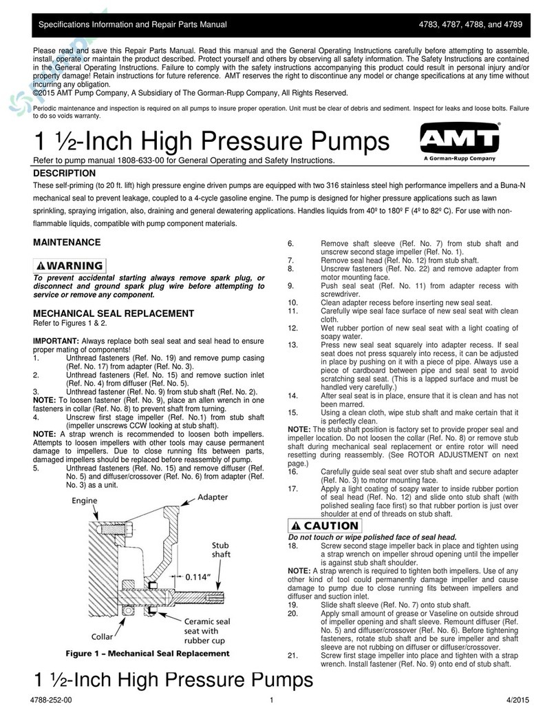
REMOVAL OF OLD SEAL
Refer to Figure 1
IMPORTANT: Always replace both seal seat (Ref. No. 10) and seal head (Ref.
No. 11) to ensure proper mating of components! Also, impeller seal washer
(Ref. No. 14) should be replaced anytime impeller lock bolt (Ref. No. 15) has
been removed.
1. Remove four bolts (Ref. No. 4) that connect adapter (Ref. No. 7) to casing
(Ref. No. 16).
2. Remove casing and casing seal (Ref. No. 8).
Care should be taken not to “pinch” or “shave” the o-ring gasket (Ref. No. 8)
between adapter and casing.
3. Using an Allen wrench, remove impeller lock bolt, impeller seal washer,and
impeller (Ref. No. 13).
IMPORTANT: Care should be taken to ensure that same number of shim
washers (Ref. No. 12) are replaced behind impeller as were removed. These
shim washers are located directly behind impeller. These washers as well as
impeller key (Ref. No. 2) become loose as impeller is removed.
4. Seal head and shaft sleeve can now be pulled from shaft.
5. Pry seal seat from adapter.
6. Push seal head from shaft sleeve.
INSTALLATION OF NEW SEAL
The precision lapped faces on mechanical seal are easily damaged. Handle
your replacement seal carefully.
1. Thoroughly clean all surfaces of seal seat cavity.
2. Using a clean cloth, wipe shaft and shaft sleeve and make certain that
they are perfectly clean.
3. Wet the rubber portion of new seal seat with a light coating of soapy water.
While wearing clean gloves or using a clean light rag, press seal seat
squarely into adapter recess. Avoid scratching polished surface. If seal will
not position properly, place a cardboard washer over polished surface and
use a piece of pipe to press in, rmly but gently.
4. Dispose of cardboard washer. Check again to see that polished surface is
free of dirt and all other foreign particles and that it has not been scratched
or damaged.
5. Wet the inside of rubber portion of new seal head with a light coating of
soapy water. Slide head onto shaft sleeve. Slide shaft sleeve with seal
head onto motor shaft. Seal head and seal seat will meet. Reinstall any
shims which have been removed. (See SHIM ADJUSTMENT section.)
IMPORTANT: Before installing new shaft sleeve, apply a bead of non-
hardening, pliable sealant (such as Permatex®, Form-A-Gasket® No. 2) to
motor shaft shoulder.
6. Replace impeller key and impeller. Replace impeller seal washer before
screwing impeller lock bolt in place.
7. Reassemble pump.
8. A short “run-in” period may be necessary to provide completely leak free
seal operation.
DESCRIPTION
These centrifugal pumps are self-priming (to 20 ft. lift) units designed for high volume liquid transfer – irrigation, de-watering, lawn sprinkling, etc. They can also
accommodate semi-solids (up to 3/8” diameter), sediment laden liquids and liquids with entrained air or gases. Casing working pressure to 125 psi (862 kPa).
The units are equipped with a cast iron pump casing designed with a full dual volute, clog resistant semi-open stainless steel impeller and a cast iron adapter.
Units are equipped with apper valves to ensure a positive prime. A mechanical seal isolates the motor from the liquid in the pump casing. The units are coupled
to 3450 RPM, totally enclosed fan cooled motors. All units are manual models, no controls are supplied. For use with nonammable, non-abrasive liquids compat-
ible with pump component materials.
Specications Information and Repair Parts Manual 2874-95 thru 2879-95
2874-251-00 2 10/2016
SHIM ADJUSTMENT
When installing a replacement impeller (Ref. No. 13) or motor (Ref. No. 1),
it may be necessary to adjust the number of shims (Ref. No. 12) to ensure
proper running clearance between impeller and casing (Ref. No. 16). Proceed
as follows:
NOTE: A proper running clearance is less than 0.010”.
1. For impeller replacement, add one (1) shim in addition to those removed
originally.
2. For motor replacement, add two (2) shims in addition to shims removed
during disassembly.
3. Reassemble pump as described in steps 6 and 7. (See INSTALLATION
OF NEW SEAL section.)
IMPORTANT: Be sure that casing is snugly in place and check shaft to make
sure it is turning freely (use screwdriver slot in the motor to turn shaft). If it turns
freely, check to ensure that adapter (Ref. No. 7) and casing are tted metal
-to- metal where they meet on outside. If they are not metal-to-metal, tighten
fasteners (Ref. No. 4) and recheck shaft for free turning. Tighten carefully,
turning shaft while tightening so that motor bearings are not damaged in the
event that too many shims were installed. If shaft seizes before fasteners are
completely tight, disassembly pump and remove one (1) shim and repeat
reassembly.
For Repair Parts contact dealer where pump was purchased.
Please provide following information:
-Model Number
-Serial Number (if any)
Part description and number as shown in parts list
Figure 1 - Repair Parts Illustrations
3-Inch Self-Priming Centrifugal Pumps
Specications Information and Repair Parts Manual 2874-95 thru 2879-95
2874-251-00 3 10/2016
Part Number for Models
3HP 5HP 7.5HP
Ref 2877-95 2878-95 2879-95
No. Description 2874-95 2875-95 2876-95 Qty
1 Motor - 1 Phase TEFC 1626-082-00 1626-078-00 1626-079-00 1
Motor - 3 Phase TEFC 1627-351-00 1627-352-00 1627-353-00 1
2 Impeller Key 1471-030-00 1471-030-00 1471-030-00 1
3 Slinger Washer 1470-093-00 1470-093-00 1470-093-00 1
4 Fastener * * * 4
5 Washer * * * 8
6 Washer * * * 12
7Adapter Assembly 1470-001-90 1470-001-90 1470-001-90 1
8 O-Ring & Flapper Valve Kit - Buna 2870-301-91 2870-301-91 2870-301-91 1
O-Ring & Flapper Valve Kit - Viton 2870-301-92 2870-301-92 2870-301-92 1
(includes Ref. Nos. 8, 14 and 19)
9 Shaft Sleeve 1555-142-00 1555-142-00 1555-142-00 1
10 & 11 Seal Assembly Buna (standard) 1640-163-90 1640-163-90 1640-163-90 1
Seal Assembly Viton (optional) 1640-163-91 1640-163-91 1640-163-91 1
12 Impeller Shim Set 1664-000-90 1664-000-90 1664-000-90 1
13 Impeller Kit 2874-013-90 2875-013-90 2876-013-90 1
(includes Ref. Nos. 13, 14 and 15)
14 Impeller Seal Washer Incl. w/Ref. 8 & 13 Incl. w/Ref. 8 & 13 Incl. w/Ref. 8 & 13 1
15 Impeller Screw Incl. w/Ref. 13 Incl. w/Ref. 13 Incl. w/Ref. 13 1
16 Casing 1543-003-01 1543-003-01 1543-003-01 1
17 3/4” NPT Pipe Plug * * * 3
18 Suction Plate 1589-000-01 1589-000-01 1589-000-01 1
19 Flapper Valve Assembly Incl. w/Ref. 8 Incl. w/Ref. 8 Incl. w/Ref. 8 1
20 Screw * * * 8
(*) Standard hardware item, available locally.
Repair Parts List

This manual suits for next models

5

Other AMT Water Pump manuals

AMT 4410-95 Assembly instructions

AMT

AMT 4410-95 Assembly instructions

AMT 5497 Assembly instructions

AMT

AMT 5497 Assembly instructions

AMT 489G-95 Assembly instructions

AMT

AMT 489G-95 Assembly instructions

AMT 489G-98 Assembly instructions

AMT

AMT 489G-98 Assembly instructions

AMT 5830 Assembly instructions

AMT

AMT 5830 Assembly instructions

AMT 4222-95 Assembly instructions

AMT

AMT 4222-95 Assembly instructions

AMT Contractor Series Assembly instructions

AMT

AMT Contractor Series Assembly instructions

AMT 4294-251 Assembly instructions

AMT

AMT 4294-251 Assembly instructions

AMT 2827-98 1/2HP Assembly instructions

AMT

AMT 2827-98 1/2HP Assembly instructions

AMT 335 Series User manual

AMT

AMT 335 Series User manual

AMT 4381-96 Assembly instructions

AMT

AMT 4381-96 Assembly instructions

AMT 4S13XAR Assembly instructions

AMT

AMT 4S13XAR Assembly instructions

AMT 2762-98 1-1/2HP Assembly instructions

AMT

AMT 2762-98 1-1/2HP Assembly instructions

AMT 5580 Assembly instructions

AMT

AMT 5580 Assembly instructions

AMT 489 Series Assembly instructions

AMT

AMT 489 Series Assembly instructions

AMT 4292-96 Assembly instructions

AMT

AMT 4292-96 Assembly instructions

AMT 4292-96 Assembly instructions

AMT

AMT 4292-96 Assembly instructions

AMT 3899-98 Assembly instructions

AMT

AMT 3899-98 Assembly instructions

AMT 5761-95B Assembly instructions

AMT

AMT 5761-95B Assembly instructions

AMT 4660-99 Assembly instructions

AMT

AMT 4660-99 Assembly instructions

AMT 3680 Series Assembly instructions

AMT

AMT 3680 Series Assembly instructions

AMT 3941-96 Assembly instructions

AMT

AMT 3941-96 Assembly instructions

AMT 5760-95 Assembly instructions

AMT

AMT 5760-95 Assembly instructions

AMT 2852-95 Assembly instructions

AMT

AMT 2852-95 Assembly instructions

Popular Water Pump manuals by other brands

Danfoss APP S Series Disassembling and assembling

Danfoss

Danfoss APP S Series Disassembling and assembling

Ingersoll-Rand ARO BD20-A Series Operator's manual

Ingersoll-Rand

Ingersoll-Rand ARO BD20-A Series Operator's manual

vacuumbrand PC 3001 basic Instructions for use

vacuumbrand

vacuumbrand PC 3001 basic Instructions for use

Graco SaniForce 24N300 Instructions - parts

Graco

Graco SaniForce 24N300 Instructions - parts

Pontec PondoMax Eco 1500 operating instructions

Pontec

Pontec PondoMax Eco 1500 operating instructions

Vogelsang VX100Q operating instructions

Vogelsang

Vogelsang VX100Q operating instructions

FMT Swiss AG PREMAxx operating instructions

FMT Swiss AG

FMT Swiss AG PREMAxx operating instructions

YAMADA Global Series Maintenance manual

YAMADA

YAMADA Global Series Maintenance manual

Pentair NOCCHI MULTI EVO Series instruction manual

Pentair

Pentair NOCCHI MULTI EVO Series instruction manual

Homa GRP Series Installation, operation and maintenance manual

Homa

Homa GRP Series Installation, operation and maintenance manual

GORMAN-RUPP PUMPS Super T T6B60S-B Installation, operation and maintenance manual

GORMAN-RUPP PUMPS

GORMAN-RUPP PUMPS Super T T6B60S-B Installation, operation and maintenance manual

Dover PSG ALL-FLO F100 Series Installation operation & maintenance

Dover

Dover PSG ALL-FLO F100 Series Installation operation & maintenance

BUSCH MINK MM 1104 CVM instruction manual

BUSCH

BUSCH MINK MM 1104 CVM instruction manual

Wilden Saniflo PS4 Hygienic Series Engineering, operation & maintenance

Wilden

Wilden Saniflo PS4 Hygienic Series Engineering, operation & maintenance

Taco 001-3914 instruction sheet

Taco

Taco 001-3914 instruction sheet

BUSCH R5 RA 0025F instruction manual

BUSCH

BUSCH R5 RA 0025F instruction manual

Textron Greenlee EHP700LU instruction manual

Textron

Textron Greenlee EHP700LU instruction manual

Sartorius 16419 operating instructions

Sartorius

Sartorius 16419 operating instructions

manuals.online logo
manuals.online logoBrands
  • About & Mission
  • Contact us
  • Privacy Policy
  • Terms and Conditions

Copyright 2025 Manuals.Online. All Rights Reserved.