Table of Contents
i
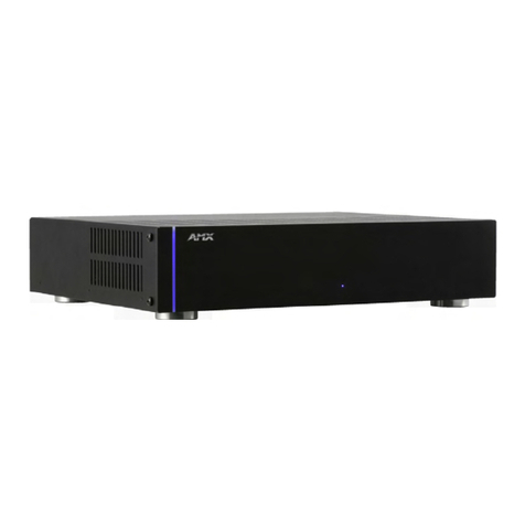
ALR-AMP-8 Alero 8 Zone Power Amplifier
Table of Contents
Important Safety Instructions.................................................................................... a
Alero ALR-AMP-8 8 Zone Power Amplifier .........................................................1
Overview .................................................................................................................. 1
Common Application....................................................................................................... 1
Product Features ............................................................................................................. 1
Product Specifications .............................................................................................. 1
Front Panel Components (LEDs) ...................................................................................... 3
POWER LED (Green/Red)............................................................................................................ 3
OC/CLIP LED (Yellow/Red).......................................................................................................... 3
THERMAL LED (Red) ................................................................................................................... 3
Rear Panel Components .................................................................................................. 3
System Diagram .............................................................................................................. 4
Controlling the Alero ALR-AMP-8 ................................................................................... 4
Installation ..........................................................................................................5
Mounting the Alero into an Equipment Rack............................................................ 5
Ventilation ....................................................................................................................... 5
Rack Mount Safety Instructions ....................................................................................... 5
Wiring and Connections............................................................................................ 5
Connecting Audio Source Devices................................................................................... 5
Audio (Signal) Inputs................................................................................................................... 6
SE/BTL (Stereo/Bridge Mode) Switches (1-8).............................................................................. 6
Connecting Input Devices in Stereo Mode ...................................................................... 6
Connecting Input Devices in Bridge Mode ...................................................................... 7
Connecting Speakers ................................................................................................ 7
Speaker Output Connectors ....................................................................................................... 8
Connecting Speakers in Stereo Mode ............................................................................. 8
Connecting Speakers in Bridge Mode ............................................................................. 9
I/O (Control Input) Port........................................................................................... 10
Pin 1 - Signal Sense ....................................................................................................... 10
External Signal Sense Switch .................................................................................................... 11
Pin 3 - 12V (In) Trigger .................................................................................................. 11
Pin 4 - Trigger (Loop Out) ............................................................................................. 11
Pin 5 - Local/Trigger GND ............................................................................................. 12
Pin 6 - 3-5V Logic Level Trigger .................................................................................... 12
3-5V Trigger Switch .................................................................................................................. 12
Pins 7 & 8 - Thermal Overload and OC (Overcurrent) Monitor Indicators ..................... 12
Pin 9 - On Signal Output / 12V Trigger ......................................................................... 13
On Signal Output...................................................................................................................... 13
12V Trigger............................................................................................................................... 13
Pin 10 - Status GND ...................................................................................................... 14
