AMX AXB-MPE Plus User manual

instruction manual
Axcess Central Controllers and Cards
AXB-MPE+
Master Port Expander
AXB-SPE
Slave Port Expander

AMX Limited Warranty and Disclaimer
AMX Corporation warrants its products to be free of defects in material and workmanship under normal use for
three (3) years from the date of purchase from AMX Corporation, with the following exceptions:
• Electroluminescent and LCD Control Panels are warranted for three (3) years, except for the display and touch
overlay components that are warranted for a period of one (1) year.
• Disk drive mechanisms, pan/tilt heads, power supplies, MX Series products, and KC Series products are
warranted for a period of one (1) year.
• Unless otherwise specified, OEM and custom products are warranted for a period of one (1) year.
• Software is warranted for a period of ninety (90) days.
• Batteries and incandescent lamps are not covered under the warranty.
This warranty extends only to products purchased directly from AMX Corporation or an Authorized AMX Dealer.
AMX Corporation is not liable for any damages caused by its products or for the failure of its products to perform.
This includes any lost profits, lost savings, incidental damages, or consequential damages. AMX Corporation is not
liable for any claim made by a third party or by an AMX Dealer for a third party.
This limitation of liability applies whether damages are sought, or a claim is made, under this warranty or as a tort
claim (including negligence and strict product liability), a contract claim, or any other claim. This limitation of
liability cannot be waived or amended by any person. This limitation of liability will be effective even if AMX
Corporation or an authorized representative of AMX Corporation has been advised of the possibility of any such
damages. This limitation of liability, however, will not apply to claims for personal injury.
Some states do not allow a limitation of how long an implied warranty last. Some states do not allow the limitation or
exclusion of incidental or consequential damages for consumer products. In such states, the limitation or exclusion of
the Limited Warranty may not apply. This Limited Warranty gives the owner specific legal rights. The owner may
also have other rights that vary from state to state. The owner is advised to consult applicable state laws for full
determination of rights.
EXCEPT AS EXPRESSLY SET FORTH IN THIS WARRANTY, AMX CORPORATION MAKES NO
OTHER WARRANTIES, EXPRESSED OR IMPLIED, INCLUDING ANY IMPLIED WARRANTIES OF
MERCHANTABILITY OR FITNESS FOR A PARTICULAR PURPOSE. AMX CORPORATION
EXPRESSLY DISCLAIMS ALL WARRANTIES NOT STATED IN THIS LIMITED WARRANTY. ANY
IMPLIED WARRANTIES THAT MAY BE IMPOSED BY LAW ARE LIMITED TO THE TERMS OF THIS
LIMITED WARRANTY.

Table of Contents
i
AXB-MPE+ Master Port Expander and AXB-SPE Slave Port Expander
Table of Contents
Product Information .................................................................................................1
AXB-MPE+ Dual and Single Master Port Expanders........................................................ 1
AXB-SPE Slave Port Expander......................................................................................... 3
Installation and Configuration .................................................................................5
AXC-EM Master Card DIP Switch Settings ....................................................................... 5
PROGRAM RS-232 DIP Switch Settings .......................................................................... 6
Configuring the MPE+ to use One or Two AXC-EM Cards............................................... 7
Wiring the AXB-MPE+ and AXB-SPE ............................................................................... 8
Guidelines ................................................................................................................................ 8
Preparing captive wires............................................................................................................ 8
Using AXlink for data and a 12 VDC power supply.................................................................. 8
Connecting an AXB-MPE+ to the AXB-SPE ............................................................................ 9
Replacing the Lithium Batteries ............................................................................................... 9
256 KB Firmware Upgrade.............................................................................................. 10
256 KB Memory Upgrade................................................................................................ 11
Installing the AXB-MPE+, AXB-SPE, and External Equipment....................................... 11
AXCESS Programming ................................................................................................... 11
Programming the AXB-MPE+ (One AXC-EM Card) .............................................................. 11
Programming the AXB-MPE+ Dual Master Port Expander (Two AXC-EM Cards) ................ 12

ii AXB-MPE+ Master Port Expander and AXB-SPE Slave Port Expander
Table of Contents

Product Information
1
AXB-MPE+ Master Port Expander and AXB-SPE Slave Port Expander
Product Information
AXB-MPE+ Dual and Single Master Port Expanders
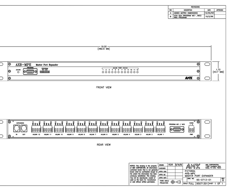
The AXB-MPE+ Dual and Single Master Port Expanders (FIG. 1) are AXCESS Control Systems
that are equipped with 12 AXlink ports that can control multiple audiovisual and lighting device up
to 3,000 feet from the control system. With the AXCESS programming software, you program the
AXC-EM cards, housed in the AXB-MPE+, to control the devices. The AXB-MPE+ Dual Master
Port Expander comes with two AXC-EM cards: the first card is the main processor and the second
is the stand-by processor. If a problem occurs with the first card, the AXB-MPE+ automatically
switches to the second card without disrupting service.
The following table lists specifications for the AXB-MPE+:
FIG. 1 AXB-MPE+ Master Port Expander and Dual Master Port Expander
AXB-MPE+ Specifications
Product Type AXlink bus expansion accessory
Program Control • AXC-EM Enhanced System Master Card built-in
• Two DB-9 RS-232 program ports
• DIP switch to set communication parameters
Device Connectors 12 four-terminal connectors for captive wire compression
Expansion Connectors Two 4-pin modular telco connectors
Power • 11.8 to 16V DC, 250mA (using 2 AXC-EM cards)
(150 mA max draw per AXC-EM card)
• 2-pin captive-wire connector
Note: Power rating does not include externally connected AXlink devices.
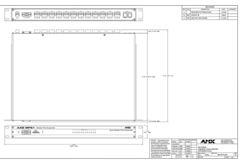
Dimensions (HWD) 1.72" x 19.00"(with rack ears) x 12.09" (4.37 cm x 48.26 cm x 30.71 cm)
Weight 6 lbs. (2.72 kg)
Rack One standard rack unit high. Rack mounts included.
AXlink 8
GND
AXM
AXP
PWR
AXM
GND
AXlink 6
AXM
PWR
GND
AXP
PWR
GND
AXlink 5 AXlink 4
GND
AXM
AXP
PWR
AXP
AXM
PWR
AXlink 3 AXlink 2
GND
AXM
AXP
PWR
GND
AXM
AXP
AXlink 1
AXP
GND
PWR
AXM
PWR
12VDC
PWR
PROGRAM MC1 / MC2
AXLINK PORT STATUS
12 435 7681091112
ON
PROGRAM
RS-232AXLINK
PROGRAM MC1
MC1
PROGRAM
RS-232
ON
MC2 21
AXLINK POR T STATUS
3547681091112
IN
AXP
AXlink 7
AXM
AXlink12EXPANSION
OUT
GND
AXlink 11
AXP
PWR
GND
AXM
AXP
PWR
AXlink 10 AXlink 9
AXP
AXM
GND
PWR
AXM
GND
AXP
PWR
AXlink status LED
PROGRAM port
PROGRAM RS-232 DIP switch AXLINK PORT STATUS LEDs
MC1 status LED
MC2 status LED
PROGRAM MC1 port
PROGRAM RS-232 DIP switch AXLINK PORT STATUS LEDs
EXPANSION IN/OUT ports
PWR connector
PROGRAM MC1 / MC2 port
AXlink connectors (1-12)
(front)
(front)
(rear)

Product Information
2AXB-MPE+ Master Port Expander and AXB-SPE Slave Port Expander
AXB-MPE+ Specifications (Cont.)
Front Panel Components:
AXlink status LED: Green LED that blinks to indicate power and AXlink communication activity.
Blink status for the AXlink LED includes:
• Off: no power or the AXC-EM Master Card is not functioning properly.
• One blink: normal operation. Device numbers match the programmed
device numbers in the AXCESS program.
• Two blinks: device numbers do not match the AXCESS program, a device
is not present, or a device is not to the right number.
• Three blinks: AXlink bus error. You should check AXlink wiring.
• Full on: AXCESS program is not present in the AXC-EM card, and there
is no AXlink activity.
MC1 and MC2 LEDs: Green LED that blinks to indicate power and AXlink communication activity
on the AXC-EM Master Cards 1 and 2. The blink patterns are identical to
those described above for the AXlink LED.
PROGRAM (MC1) port DB-9 male connector that connects to a PC or other RS-232 device. Use
the PROGRAM port to download the AXCESS programs to the AXC-EM
card.
On the Dual Master Port Expander Plus, this port is designated as
PROGRAM MC1 (Master Card #1).
PROGRAM RS-232 DIP Switch 8-position communication DIP switch that sets the baud rate, data bits, par-
ity, and stop bits. The default settings are 1 stop bit, 8 data bits, no parity,
and 38.4K baud.
AXLINK PORT STATUS LEDs 12 red LEDs that show AXlink port activity. The LEDs light when a device
connected to the port transmits data.
Rear Panel Components:
Expansion Ports (IN/OUT) Two RJ-11 4-pin modular connectors that interconnect the AXB-MPE+ and
AXB-SPE.
AXlink Ports (1-12) 12 four-pin (male) AXlink connectors. The distance between external
devices and the AXB-MPE+ is 3,000 feet (914.4 meters) for AXlink data
communication. If the external equipment requires supplemental power,
refer to the manufacturer's literature to determine what type of power sup-
ply is required.
PROGRAM port DB-9 connector (male) that connects to a PC to program the AXC-EM Mas-
ter Cards.
• For single AXC-EM Master Card configurations, you use the PROGRAM
connector to program the Master Card.
• For dual AXC-EM Master Card configurations, you use the PROGRAM
connector to program the Master Card installed in the Master #2 card slot
(MC2).
PWR connector Two-pin (male) connector that supplies 12VDC to the AXB-MPE+. The
power is distributed in parallel to each AXlink connector. The total load for
all AXlink connectors must not exceed 4 amps.

Product Information
3
AXB-MPE+ Master Port Expander and AXB-SPE Slave Port Expander
AXB-SPE Slave Port Expander
The AXB-SPE Slave Port Expander (FIG. 2) contains 12 AXlink ports that you can control with the
AXB-MPE+. You can connect the AXB-SPE to the AXB-MPE+, and then control 12 additional
AXlink bus lines. The AXB-SPE is an add-on device that connects to the AXB-MPE+ via RJ-11
modular connectors. The AXB-SPE ports are controlled by the online AXC-EM Master Card in the
AXB-MPE+.
The following table lists specifications for the AXB-SPE:
FIG. 2 AXB-SPE Slave Port Expander
AXB-SPE Specifications
Product Type AXlink bus expansion accessory
Program Control
Device Connectors 12 four-terminal connectors for captive wire compression
Expansion Connectors Two 4-pin modular telco connectors
Power • 11.8 to 16V DC, 150mA (maximum draw)
• 2-pin connector for captive wire compression
Dimensions (HWD) • 1.72" x 19.00"(with rack ears) x 12.09" (4.37 cm x 48.26 cm x 30.71 cm)
• One standard rack unit high. Rack mounts included.
Weight 6 lbs. (2.72 kg)
Front Panel Components:
AXLINK PORT STATUS LEDs 12 red LEDs that show AXlink port activity. The LEDs light when a device
connected to the port transmits data.
Rear Panel Components:
Expansion Ports (IN/OUT) Two RJ-11 4-pin connectors that interconnect the AXB-SPE and AXB-MPE+.
AXlink Ports (1-12) 12 four-pin (male) AXlink connectors. The distance between the external
AMX equipment and the AXB-MPE+ is 3,000 feet (914 meters) for AXlink
data communication. If the AMX equipment requires supplemental power,
refer to the associated product manual's to determine if supplement power is
required.
PROGRAM MC1 / MC2 port Not used.
PWR connector Two-pin (male) connector that supplies 12VDC to the AXB-SPE. The power
is distributed in parallel to each AXlink connector. The total load for all AXlink
connectors must not exceed 4 amps.
PROGRAM MC1 / MC2
EXPANSION
IN
AXlink 10
OUT
AXlink 12
GND
AXM
AXP
AXP
AXlink 11
GND
PWR
AXM
PWR
GND
AXM
GND
AXP
PWR
GND
AXlink 9
PWR
AXM
AXP
AXlink 8
AXP
AXM
PWR
AXlink 7
GND
AXM
AXP
PWR
AXlink 3
AXP
AXlink 5
PWR
AXlink 6
GND
AXM
AXP
GND
AXM
AXlink 4
PWR
GND
AXM
AXP
PWR
GND
GND
PWR
AXP
AXM
AXlink 2
AXP
AXM
PWR
AXlink 1
GND
AXM
AXP
PWR
12VDC
PWR
123456 789 1110 12
AXLINK PORT STATUS
EXPANSION IN/OUT
p
orts
PWR connector
PROGRAM MC1 / MC2
p
ort
AXlink connectors (1-12)
(rear)
AXLINK PORT STATUS LEDs

Product Information
4AXB-MPE+ Master Port Expander and AXB-SPE Slave Port Expander

Installation and Configuration
5
AXB-MPE+ Master Port Expander and AXB-SPE Slave Port Expander
Installation and Configuration
Before you install the AXB-MPE+, you should check the AXC-EM Master Card DIP switch for
correct settings, and also set the PROGRAM RS-232 DIP switch on the front panel of the AXB-
MPE+. FIG. 1 shows the orientation of the AXC-EM components discussed in this section.
AXC-EM Master Card DIP Switch Settings
All the AXC-EM Master Card DIP switch positions must be set OFF to communicate with the
AXB-MPE+.
To verify the AXC-EM Master Card DIP switch is set correctly:
1. Discharge the static electricity from your body by touching a grounded object.
2. Remove the two Phillips-head screws from the top panel on the AXB-MPE+, and slide the
panel backward to access the AXC-EM Master Cards. FIG. 1 shows the DIP switch location on
the AXC-EM card.
3. Set all the DIP switch positions OFF (down), as shown in FIG. 2. If the AXB-MPE+ is
equipped with two AXC-EM Master Cards, repeat this step on the second card.
4. Close the top panel, insert the Phillips-head screws, and tighten.
FIG. 1 AXC-EM Master Card component orientation (batteries, EPROMS, ICs and DIP switch).
FIG. 2 AXC-EM DIP switch settings
DIP switch
Lithium batteries and sockets
Firmware EPROMs
Memory ICs AXC-EM
12345678
ON

Installation and Configuration
6AXB-MPE+ Master Port Expander and AXB-SPE Slave Port Expander
PROGRAM RS-232 DIP Switch Settings
The PROGRAM RS-232 DIP switch, on the front panel of the AXB-MPE+, sets the baud rate, data
bits, stop bits, and parity communication settings. The following table lists the DIP switch
communication settings and shows a sample DIP switch setting of 1 stop bits, 8 data bits, no parity,
and 9,600 baud:
The default values are:
! 1 stop bit
! 8 data bits
! No parity
! 38.4K baud
PROGRAM RS-232 DIP Switch Settings
Switch1 2 3456 7 8
Function Stop Bits Data Bits Parity Baud Rates
Setting Off Off Off Off Off Off Off Off
Value 2 bits 7 bits Unused 300
On On On Off Off On Off Off
1 bit 8 bits Unused 600
Off On Off Off On Off
Unused 1,200
On On Off On On Off
Unused 2,400
Off Off On Off Off On
Mark 4,800
On Off On On Off On
Even 9,600
Off On On Off On On
Odd 19,200
On On On On On On
None 38,400
12345678 ON
To reset the DIP switch to its default settings, place all switches in the ON position.

Installation and Configuration
7
AXB-MPE+ Master Port Expander and AXB-SPE Slave Port Expander
Configuring the MPE+ to use One or Two AXC-EM Cards
The AXB-MPE+ Master Port Expander uses one AXC-EM master card. The AXB-MPE+ Dual
Master Port Expander uses two AXC-EM master cards. Both come factory set to either a single or
dual expander. If you are using an AXC-MPE+ Master Port Expander and want to upgrade the unit
to use two AXC-EMs:
1. Discharge the static electricity from your body by touching a grounded object.
2. Remove the two Phillips-head screws from the top panel on the AXB-MPE+, and slide the
panel backward to access the AXC-EM Master Cards (FIG. 3).
3. Locate the Jumper location (JP1A and JP1B) between the AXC-EM internal connection ports.
4. To set the Port Expander to use one master, place the jumper from JP1A on pins 1 and 2
(SINGLE) and verify that the jumper from JP1B is also on pins 1 and 2. This setting allows the
user to program the single AXC-EM card using either the front or rear Program ports. Refer to
the Programming the AXB-MPE+ (One AXC-EM Card) section on page 11 for more
information.
5. To set the Port Expander to use two master, place the jumper from JP1A on pins 2 and 3
(DUAL) and verify that the jumper from JP1B is also on pins 2 and 3. Refer to the
Programming the AXB-MPE+ Dual Master Port Expander (Two AXC-EM Cards) section on
page 12 for more information.
This setting allows the user to ONLY program:
! AXC-EM Card #1 (see FIG. 3) using the front Program port on the MPE+ and
! AXC-EM Card #2 (see FIG. 3) using the rear Program port on the MPE+.
FIG. 3 MPE+ internal locations for AXC-EM cards and respective jumpers
AXC-EM Card #2
AXC-EM Card #1
Dual/Single Master
Expander jumpers
(JP1A and JP1B)
JP1A jumper
JP1B jumper

Installation and Configuration
8AXB-MPE+ Master Port Expander and AXB-SPE Slave Port Expander
Wiring the AXB-MPE+ and AXB-SPE
You must connect a 12 VDC power supply to the AXB-MPE+ and AXB-SPE to control external
equipment. If you connect external AMX equipment, refer to the associated AMX manuals for
wiring and power supply information. This section describes how to wire a control system.
Guidelines
The AXB-MPE+ and AXB-SPE requires 12 VDC power to operate properly. The maximum wiring
distance between the control equipment and external equipment is determined by power
consumption, supplied voltage, and the wire gauge used for the cable. The maximum wiring
lengths for using AXlink power are based on a minimum of 13.5 volts available at the
AXB-MPE+'s and AXB-SPE's power supply.
Preparing captive wires
You will need a wire stripper, soldering iron, and flat-head screwdriver to prepare and connect the
captive wires.
1. Strip 0.25 inch of wire insulation off all wires and apply a light coat of solder to the ends using
a soldering iron.
2. Insert each wire into the appropriate opening on the connector according to the wiring
diagrams and connector types described in this section.
3. Turn the flat-head screws clockwise to secure the wire in the connector.
Using AXlink for data and a 12 VDC power supply
Connect the AXB-MPE+ and AXB-SPE AXlink connector to the AXlink connector on the external
equipment, and the 12 VDC power supply as shown in FIG. 4.
Do not over-torque the screw. Doing so can bend the seating pin and damage the
connector.
FIG. 4 AXlink and optional power supply wiring diagram
PWR+
AXP/TX
AXM/RX
GND-
PWR+
AXP
AXM
GND-
AXlink connector on
AXB-MPE+ or AXB-SPE
External equipment
PWR+
GND- Local 12 VDC power supply
PWR connector on
AXB-MPE+ or AXB-SPE

Installation and Configuration
9
AXB-MPE+ Master Port Expander and AXB-SPE Slave Port Expander
Connecting an AXB-MPE+ to the AXB-SPE
FIG. 5 shows how to connect the expansion cables between the AXB-MPE+ and AXB-SPE. AMX
supplies the RJ-11 module cable with the AXB-SPE.
Replacing the Lithium Batteries
There are two lithium batteries (see FIG. 1 on page 5), with a life of approximately 5 years, on the
AXC-EM Master Card that protects stored commands if there is a power loss. The batteries are not
used when DC power is supplied to the cards via the AXB-MPE+. You should write down the
replacement date on a sticker or label by adding 5 years to the date of installation, and then attach it
to the back of the AXB-MPE+
Before you replace the lithium batteries, verify that your AMX dealer has a current copy of control
commands stored in your AXB-MPE+. This will avoid any inadvertent loss of data or a service
outage.
You will need a flat-blade tool (non-conducting) that can be slipped under the lithium batteries to
pry them up and out of the sockets:
1. Discharge the static electricity from your body by touching a grounded object.
2. Disconnect all the connectors from the back panel on the AXB-MPE+. Then, remove it from
the equipment rack (if applicable), and lay it down on a non-conductive surface.
3. Remove the two Phillips-head screws from the top panel on the AXB-MPE+, and slide the
panel backward to access the lithium batteries on the AXC-EM Master Cards.
4. Carefully pry one battery out of its socket and insert the new battery.
5. Plug the power supply back into the AXB-MPE+ for approximately 1 minute. Then,
disconnect the power supply again.
6. Carefully slide the other battery out of its socket, and insert the new battery.
FIG. 5 AXB-MPE+ and AXB-SPE expansion wiring diagram
EXPANSION
A
XB
–
MPE+
A
XB
–
SPE
A
XB
–
SPE
EXPANSION
EXPANSION
IN OUT AXLINK 12
IN
IN
OUT
OUT AXLINK 12
AXLINK 12
AXLINK 1
AXLINK 1
AXLINK 1
PWR
12VDC
– +
12VDC
– +
12VDC
– +
PWR
PWR
PROGRAM
Static electricity can damage electronic circuitry. Before removing the lithium
batteries from the card, discharge any accumulated static electricity from your body
and screw-driver by touching a grounded metal object.
There is a danger of explosion if you replace the battery incorrectly. Replace the
battery with the same or equivalent type recommended by the manufacturer. Dispose
of used battery according to the manufacturer's instructions. Never recharge,
disassemble, or heat the battery above 212 °F (100 °C). Never solder directly to the
battery or expose the contents of the battery to water.

Installation and Configuration
10 AXB-MPE+ Master Port Expander and AXB-SPE Slave Port Expander
7. Close the top panel, insert the Phillips-head screws, and tighten.
8. Return the AXB-MPE+ to the equipment rack and reconnect all the connectors removed in
step 2.
256 KB Firmware Upgrade
Firmware upgrades allow you to maintain the latest available operating system for your AXB-
MPE+. This section describes how to remove and replace the firmware EPROMs on the AXC-EM
Master Cards in the AXB-MPE+. You will need a Phillips screwdriver and a non-conducting flat-
blade tool to slip under the firmware ICs to lift them out of their sockets. FIG. 1 on page 5 shows
where the firmware EPROMs are located on the AXC-EM cards.
1. Discharge the static electricity from your body by touching a grounded object.
2. Disconnect all the connectors from the back panel on the AXB-MPE+. Then, remove it from
the equipment rack (if applicable), and lay it down on a non-conductive surface.
3. Remove the two Phillips-head screws from the top panel on the AXB-MPE+, and slide the
panel backward to access the AXC-EM Master Cards.
4. Carefully pry the firmware EPROMs out of their sockets labeled U3 and U4 on card 1 and card
2 (if applicable) with a non-conducting flat-blade tool, and install the new firmware EPROMs
as shown in FIG. 6.
5. Close the top panel, insert the Phillips-head screws, and tighten.
6. Return the AXB-EM+ to the equipment rack and reconnect all the connectors removed in
step 2.
FIG. 6 EPROM and IC removal and replacement
Pin 1
Pin socket 3

Installation and Configuration
11
AXB-MPE+ Master Port Expander and AXB-SPE Slave Port Expander
256 KB Memory Upgrade
You can replace the 64 KB integrated circuits (IC) on the AXC-EM Master Cards with the optional
256 KB upgrade ICs to increase storage capacity and processor speed. You will need a Phillips
screwdriver and non-conducting flat-blade tool to slip under the 64 KB ICs and pry them out of
their sockets. FIG. 1 on page 5 shows where the memory ICs are located on the AXC-EM cards.
1. Discharge the static electricity from your body by touching a grounded object.
2. Disconnect all the connectors from the back panel on the AXB-MPE+. Then, remove it from
the equipment rack (if applicable), and lay it down on a non-conductive surface.
3. Remove the two Phillips-head screws from the top panel on the AXB-MPE+, and slide the
panel backward to access the AXC-EM Master Cards.
4. Carefully pry the memory ICs out of their sockets labeled U1 and U2 on card 1 and card 2 (if
applicable) with a non-conducting flat-blade tool, and install the new memory ICs as shown in
FIG. 6.
5. Close the top panel, insert the Phillips-head screws, and tighten.
6. Return the AXB-EM+ to the equipment rack and reconnect all the connectors removed in
step 2.
Installing the AXB-MPE+, AXB-SPE, and External
Equipment
Install the AXB-MPE+ into a standard 19-inch rack using the supplied rack kit:
1. Mount the AXB-MPE+ and AXB-SPE in the equipment rack. Connect the power supply.
2. Mount the external AMX equipment where it will be used.
AXCESS Programming
You can program the AXC-EM Master Cards in the AXB-MPE+ with an AXCESS software
program to control a wide variety of audiovisual, lighting, and audio equipment. This section
describes how to program the AXB-MPE+ equipped with one or two AXC-EM Master Cards, and
also the wiring diagram for the DB-9 PROGRAM connector. Refer to the AXCESS Programming
Language instruction manual for more detailed information.
Programming the AXB-MPE+ (One AXC-EM Card)
To program the AXC-EM Master Card in the AXB-MPE+ Master Port Expander:
1. Discharge the static electricity from your body by touching a grounded object.
2. Connect your PC to the DB-9 connector on the front or back of the AXB-MPE+. FIG. 1 on
page 5 shows where the PROGRAM DIP switch is located on the front and back panel of the
AXB-MPE+. The following table shows a DB-9 wiring diagram and pinouts.

Installation and Configuration
12 AXB-MPE+ Master Port Expander and AXB-SPE Slave Port Expander
3. Launch the AXCESS software program, select the appropriate AXCESS software program,
and download it into the AXB-MPE+. Refer to the AXCESS Programming Language
instruction manual for detailed programming and downloading information.
Programming the AXB-MPE+ Dual Master Port Expander (Two AXC-EM Cards)
To program both AXC-EM Master Cards in the AXB-MPE+ Dual Master Port Expander:
1. Discharge the static electricity from your body by touching a grounded object.
2. Connect your PC to the DB-9 connector on the front of the AXB-MPE+ to program the AXC-
EM Master Card 1 (MC1). FIG. 1 on page 5 shows where the PROGRAM MC1 and
PROGRAM DIP switches are located on the front panel. Refer to Wiring the DB-9 Connector
for a DB-9 wiring diagram and pinouts.
3. Launch the AXCESS software program, select the appropriate AXCESS software program,
and download it into the AXB-MPE+. Refer to the AXCESS Programming Language
instruction manual for detailed programming and downloading information.
4. Connect your PC to the DB-9 connector on the rear of the AXB-MPE+ to program the
AXC-EM Master Card 2 (MC2). Then, perform step 3 to program the card.
Program Connector and Pinouts
Pin Signal
2RXD
3TXD
4 +12 VDC
5GND
7 +12 VDC
Pin 1
Pin 9
Refer to the PROGRAM RS-232 DIP Switch Settings section on page 6 for
communication settings.

Installation and Configuration
13
AXB-MPE+ Master Port Expander and AXB-SPE Slave Port Expander

AMX reserves the right to alter specifications without notice at any time.
brussels • dallas • los angeles • mexico city • philadelphia • shanghai • singapore • tampa • toronto* • york
3000 research drive, richardson, TX 75082 USA • 469.624.8000 • 800.222.0193 • fax 469.624.7153 • technical support 800.932.6993
032-004-1019 4/02 ©2002 AMX Corporation. All rights reserved. AMX, the AMX logo, the building icon, the home icon, and the light bulb icon are all trademarks of AMX Corporation.
AMX reserves the right to alter specifications without notice at any time. *In Canada doing business as Panja Inc.
Other manuals for AXB-MPE Plus
1
This manual suits for next models
1
Table of contents
Other AMX Extender manuals