manuals.online logo
Brands
  1. Home
  2. •
  3. Brands
  4. •
  5. AMX
  6. •
  7. Touch Panel
  8. •
  9. AMX MST-431 User manual

AMX MST-431 User manual

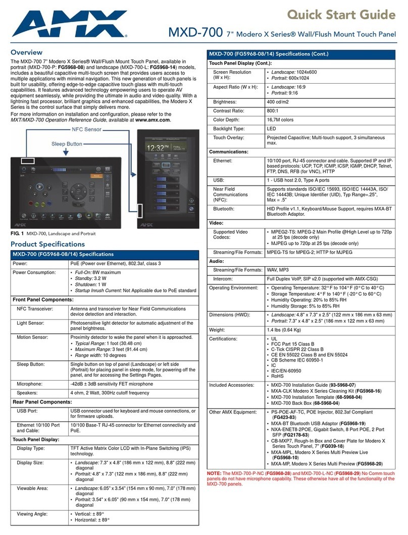
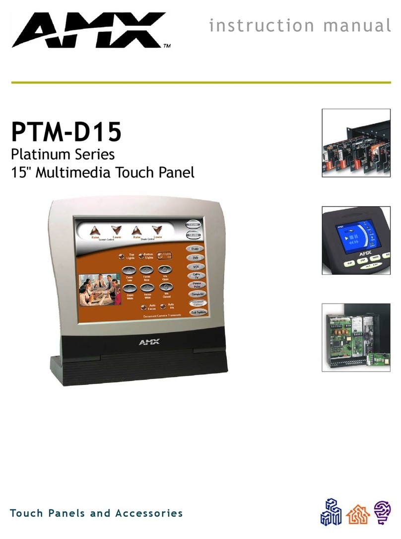
Quick Start Guide
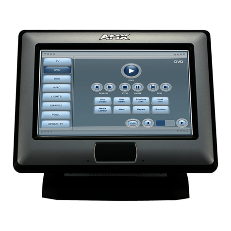
MST-431 4.3” Modero S Series Tabletop Touch Panel
Overview
The MST-431 4.3" Tabletop Touch Panel (FG2265-07) features advanced technology
empowering users to conduct seamless meetings including VoIP, brilliant 24-bit color depth,
PoE connectivity, USB and streaming video. The MST-431 also supports Bluetooth keyboard
and mouse use via the optional MXA-BT Bluetooth Adapter.
Product Specifications
Connector Locations
USB peripherals (mouse, keyboard, etc.) may be connected to the USB port on the rear of
the device. Updates to the device’s firmware can also made via the USB port.
Power via Power Over Ethernet
Power for the MST-431 is supplied via Power OverEthernet (PoE), utilizing an AMX-certified,
capacitive touch-compliant PoE injector such as the PS-POE-AT-TC High Power PoE
Injector (FG423-83) or other approved AMX PoE power source.
The incoming Ethernet cable should be connected to the RJ45 port on the panel.
Configuring and Programming
S Series touch panels are equipped with a Settings menu that provides the ability to set and
configure various features on the panels.
Note: Information on the Settings menu, panel configuration and programming is provided in
the Modero S Series Programming Guide, available at www.amx.com.
Accessing the Settings Menu
To access the Settings menu, press and hold the Sleep button on the top of the panel for 3
seconds. This invokes an on-screen prompt to release the button to enter the main Settings
page (FIG. 3).
Accessing the Configuration Page
1. From the Settings menu, select Configuration.
If the Configuration page is password protected, this opens a password keypad.
2. Enter the panel password into the keypad (the default is 1988) and select OK to access
the page (FIG. 4).
• To reboot the panel, press and hold the text under the Reboot section for two seconds.
• To shut down the panel, press and hold the text under the Shutdown section for two
seconds.
Setting the Panel’s Device Number and Device Name
In the Configuration page:
1. Press Panel to open the Panel Configuration page.
2. In the Device Name page, ensure that the Synchronize Device Names button is not
selected, and click it to deselect it if it is.
3. Press Device Number to open the Device Number keypad.
4. Enter a unique Device Number assignment for the panel and press OK.
5. Press the Device Name field to open the Device Name keypad.
6. Enter a unique Device Name assignment for the panel and press OK.
7. Click the arrow on the top left of the page once to return to the Configuration page and
twice to return to the Settings page.
FIG. 1 MST-431
MST-431 Specifications
Dimensions (HWD) 3 1/4" x 5 1/16" x 3 1/8" (82 mm x 128 mm x 79 mm)
Weight 0.9 lbs (.4 Kg)
Power Consumption • Full-On: 4 W
• Typical: 3 W
• Standby: 2 W
• Shutdown: 0.7 W
• Start-Up Inrush Current: Not applicable due to PoE standard
External Power
Supply Required Optimal performance requires use of one of the following AMX
PoE power supplies (not included):
• PS-POE-AF-TC, PoE Injector, 802.3AF Compliant
(FG423-83)
• NXA-ENET8-2POE, Gigabit PoE Ethernet Switch
(FG2178-63)
Certifications • FCC Part 15 Class B
• CE EN 55022, 55024, 60950-1
• IEC 60950-1
• C-Tick CISPR 22 Class B
• IC CISPR 22 Class B
• UL 60950-1
• VCCI CISPR 22 Class B
•RoHS
•WEEE
Environmental • Temperature (Operating): 32° F to 104° F (0° C to 40° C)
• Temperature (Storage): 4° F to 140° F (-20° C to 60° C)
• Humidity (Operating): 20% to 85% RH
• Humidity (Storage): 5% to 85% RH
• Power ("Heat") Dissipation:
On: 13.6 BTU/hr
Standby: 10.9 BTU/hr
Included
Accessories • MXA-USB-C, USB Port Cover Kit (FG5968-18)
• Cat5e Ethernet Cable, Flat Black (ECA2265-10)
• UTP CAT.5E Snap In Coupler, Black
FIG. 2 MST-431 USB Port Location
Sleep Button Microphone
USB Port
USB Port
RJ-45 Port
Speaker
FIG. 3
Settings
menu
FIG. 4
Configuration
page
For full warranty information, refer to the AMX Instruction Manual(s) associated with your Product(s).
8/14
©2014 AMX. All rights reserved. AMX and the AMX logo are registered trademarks of AMX.
AMX reserves the right to alter specifications without notice at any time.
3000 RESEARCH DRIVE, RICHARDSON, TX 75082 • 800.222.0193 • fax 469.624.7153 • technical support 800.932.6993 • www.amx.com
93-2265-07 REV: F
Accessing the Connection & Networks Page
1. From the Settings menu, select Connection & Networks.
If the page is password protected, this opens a password keypad.
2. Enter the panel password into the keypad (the default is 1988) and select OK to access
the page (FIG. 5).
Configuring the Panel’s IP Address
The first step is to configure the panel’s communication parameters. This only configures the
panel to communicate with a network, and it is still necessary to tell the panel with which
Master it should be communicating.
Network Communication With a DHCP Address
In the Connection & Networks page:
1. Select Network Connection to open the Network Connection page (FIG. 6).
2. Toggle the DHCP/Static field until the choice cycles to DHCP. This action causes all fields
on the page (other than Host Name) to be disabled.
3. Select Host Name to open the Host Name keyboard. Enter the new host name and click
OK.
Setting Static IP Information
When using DHCP settings for a panel, the DHCP server will automatically populate almost
all of the Network Connections page fields, with the exception of Hostname. When setting
the panel for Static, however, this information must be entered manually. To enter the
network connection information:
1. In DHCP/Static, press the field until the entry reads “Static”. This enables all of the
editable Network Connections page fields.
2. Select the IP Address field to open the Wired IP Address keypad (FIG. 7).
3. Enter the server’s IP address and click OK.
4. Repeat this procedure with the other fields on the Network Connections page.
5. When finished, the new connection information will be visible in the Network Connections
page.
Connecting to a NetLinx Master
To establish the type of connection to make between the panel and NetLinx Master:
1. In the Connection & Networks page, select Master Connection to open the Master
Connection page (FIG. 8).
2. Press Mode to toggle through the available connection modes (Auto, URL or Listen):
3. If you have enabled password security on your Master, you need to set the username
and password within the device.
a. Select Username to open the Master User keyboard.
b. Set your Username and select OK.
c. Select the Password to open the Master Password keyboard.
d. Set your Master Password and select OK.
e. Press the Back button twice to return to the Settings page.
Related Software and Additional Documentation (at www.amx.com)
• Programming the Modero S Series touch panels requires the use ofthe latest versions
of NetLinx Studio and TPDesign4, both available to download at www.amx.com. Refer
to the NetLinx Studio and TPDesign4 online help for information.
• For additional information on the MST-431 panel, refer to the S-Series Touch Panels
MSD/T-1001 , MSD/T-701 & MSD/T-431 Instruction Manual.
• For detailed information on the Settings menu as well programming information and
instructions on upgrading firmware, refer to the Modero S Series Programming Guide.
FIG. 5
Connection & Networks
page
FIG. 6
Network Connection
page
FIG. 7
Wired IP Address
keyboard
FIG. 8
Master Connection
page
Connection Modes
Mode Description Procedures
URL The device connects to the
target Master’s IP address
via a TCP connection.
1) Select URL in the Mode menu.
2) Enter the Master IP/URL, Master Port Number,
and Username/Password (if required by the
Master).
Press OK to save changes.
Listen This mode allows the panel
to “listen” for the Master’s
communication signals.
Note that in this mode, the
System Number and Master
IP/URL fields are read-only.
1) Select Listen in the Mode menu.
2) Confirm the panel’s IP address is on the
Master’s URL list (via NetLinx Studio).
3) Press OK to save changes.
Note: The Host Name can be used to locate the
panel on the Master (particularly useful for DHCP
connections where the IP address can change).
Auto Use this mode when both
the panel and the NetLinx
Master are on the same
Subnet.
1) Select Auto in the Mode menu.
2) Enter the System Number and Username and
Password (if applicable).
3) Press OK to save changes.
Other manuals for MST-431

4

This manual suits for next models

2

Other AMX Touch Panel manuals

AMX modero NXD-CV17 User manual

AMX

AMX modero NXD-CV17 User manual

AMX AXD-LC Guide

AMX

AMX AXD-LC Guide

AMX Modero ViewPoint MVP-7500 Parts list manual

AMX

AMX Modero ViewPoint MVP-7500 Parts list manual

AMX AXU-MCV Guide

AMX

AMX AXU-MCV Guide

AMX MXT-700 User manual

AMX

AMX MXT-700 User manual

AMX MT-1002 User manual

AMX

AMX MT-1002 User manual

AMX Modero NXD-1000Vi Parts list manual

AMX

AMX Modero NXD-1000Vi Parts list manual

AMX Modero NXD-1200V User manual

AMX

AMX Modero NXD-1200V User manual

AMX MSD-431-L User manual

AMX

AMX MSD-431-L User manual

AMX ViewPoint User manual

AMX

AMX ViewPoint User manual

AMX MODERO NXT-CA12 User instructions

AMX

AMX MODERO NXT-CA12 User instructions

AMX Color Active-Matrix LCD User manual

AMX

AMX Color Active-Matrix LCD User manual

AMX Modero NXD-700Vi Parts list manual

AMX

AMX Modero NXD-700Vi Parts list manual

AMX 10.4 TOUCH PANELS (G3 FIRMWARE) User manual

AMX

AMX 10.4 TOUCH PANELS (G3 FIRMWARE) User manual

AMX Modero MXT-1001 User manual

AMX

AMX Modero MXT-1001 User manual

AMX Modero NXD-1200VG User manual

AMX

AMX Modero NXD-1200VG User manual

AMX AXM-MCA Guide

AMX

AMX AXM-MCA Guide

AMX Electroluminescent LCD Touch Panels User manual

AMX

AMX Electroluminescent LCD Touch Panels User manual

AMX NXD-CA15 User instructions

AMX

AMX NXD-CA15 User instructions

AMX Modero ViewPoint MVP-5150 User manual

AMX

AMX Modero ViewPoint MVP-5150 User manual

AMX Modero NXD-1500VG User instructions

AMX

AMX Modero NXD-1500VG User instructions

AMX MXD-1900L-PAN User manual

AMX

AMX MXD-1900L-PAN User manual

AMX modero NXD-CV17 Installation instructions manual

AMX

AMX modero NXD-CV17 Installation instructions manual

AMX MST-431 User manual

AMX

AMX MST-431 User manual

Popular Touch Panel manuals by other brands

Zennio FLAT user manual

Zennio

Zennio FLAT user manual

Joy-it RB-LCD10 user manual

Joy-it

Joy-it RB-LCD10 user manual

Sygonix SY 1885110 operating instructions

Sygonix

Sygonix SY 1885110 operating instructions

Belden thinklogical TPL-7 manual

Belden

Belden thinklogical TPL-7 manual

Cincoze CS-W121C/P1101 user manual

Cincoze

Cincoze CS-W121C/P1101 user manual

Digital Electronics Corporation PLB910-42 installation guide

Digital Electronics Corporation

Digital Electronics Corporation PLB910-42 installation guide

Aplex ARCHMI-8XX Series user manual

Aplex

Aplex ARCHMI-8XX Series user manual

Unipulse DeviceNet F381A Operation manual

Unipulse

Unipulse DeviceNet F381A Operation manual

Bender COMTRAXX MK2430 quick start

Bender

Bender COMTRAXX MK2430 quick start

Winmate T5-series user guide

Winmate

Winmate T5-series user guide

Beckhoff CP6600 manual

Beckhoff

Beckhoff CP6600 manual

IEI Technology PPC-F17A-H81 user manual

IEI Technology

IEI Technology PPC-F17A-H81 user manual

Grossenbacher Systeme SmartPanel SP-284-10P-R00 operating instructions

Grossenbacher Systeme

Grossenbacher Systeme SmartPanel SP-284-10P-R00 operating instructions

Extron electronics TLP 700MV Setup guide

Extron electronics

Extron electronics TLP 700MV Setup guide

Crestron DualTouch DTT-17 Operation guide

Crestron

Crestron DualTouch DTT-17 Operation guide

SKYDANCE T11-1 user manual

SKYDANCE

SKYDANCE T11-1 user manual

Aquabrim fx-4i installation guide

Aquabrim

Aquabrim fx-4i installation guide

Rohloff Caliber 2 manual

Rohloff

Rohloff Caliber 2 manual

manuals.online logo
manuals.online logoBrands
  • About & Mission
  • Contact us
  • Privacy Policy
  • Terms and Conditions

Copyright 2025 Manuals.Online. All Rights Reserved.