Pentair HYDROMATIC H-03-400 Manual

NOTE! To the installer: Please make sure you provide this manual to the owner of the equipment or to the responsible
party who maintains the system.
ELECTRICAL PANELS
WITH INTRINSICALLY SAFE
CIRCUIT EXTENSIONS
INSTALLATION AND SERVICE MANUAL
Item # H-03-400 | Part # 5625-400-1 | © 2015 Pentair Ltd. | 01/09/15

2
General
Information
Attention:
This manual contains important
information for the safe use
of this product. Read this
manual completely and do not
throw away. Reasonable care
and safe methods should be
practiced. Check local codes and
requirements before installation.
Warning: Before handling pumps
and controls, always disconnect
the power first. Do not smoke or
use sparkable electrical devices
or flames in a septic (gaseous) or
possible septic sump.
Unpacking Panel:
When unpacking the unit, check
for concealed damage. Claims
for damage must be made at
the receiving end through the
delivery carrier. Damage cannot
be processed from the factory.
CALIFORNIA PROPOSITION
65 WARNING:
This product and
related accessories contain
chemicals known to the
State of California to cause
cancer, birth defects or other
reproductive harm.
Panel
Installation
Electrical Connections:
Panel Opening – Wiring: The
enclosure opening for intrinsically
safe wires must not be used for
non-intrinsically safe wiring.
This is to be the only opening in
the intrinsically safe area of the
enclosure. If this is not done, the
UL Listing for the control panel
will be void.
Electrical Connections:
The contractor must conform
to the latest requirements of the
National Electrical Code. All
conduit and cables shall have
conduit per NEC Code NFPA
#70, where conduit and cable
leave the hazardous locations.
Prior to conducting any
installation, repair or service with
regard to the control panel, refer
to the schematic appropriate for
that panel. The schematic will
provide guidance with regard
to terminal block connections.
Electrical ratings are indicated on
the schematic for terminal blocks
used in interfacing with controls
remote from the control panel. If
these ratings are violated, the UL
Listing for the control panel will
be void.
Make the Following Electrical
Connections:
Connect the pump heat sensor
and seal failure leads to the
appropriate terminal blocks in
the non-intrinsically safe area
outside the barrier in the control
panel. Connect all the float
control leads to the appropriate
panel terminal blocks in the
intrinsically safe area within
the barrier in the control panel.
If guaranteed submergence of
the pumps is critical to this
installation, contractor must
be very careful in locating the
floats at the proper elevations.
The maximum distance between
the control panel and the floats
is the lesser of 300 feet or the
maximum distance recommended
for the pump.
Connect the pump leads to the
overload relay on the control
panel. When connecting the
pump leads it is very critical
that the proper sequence
be maintained.
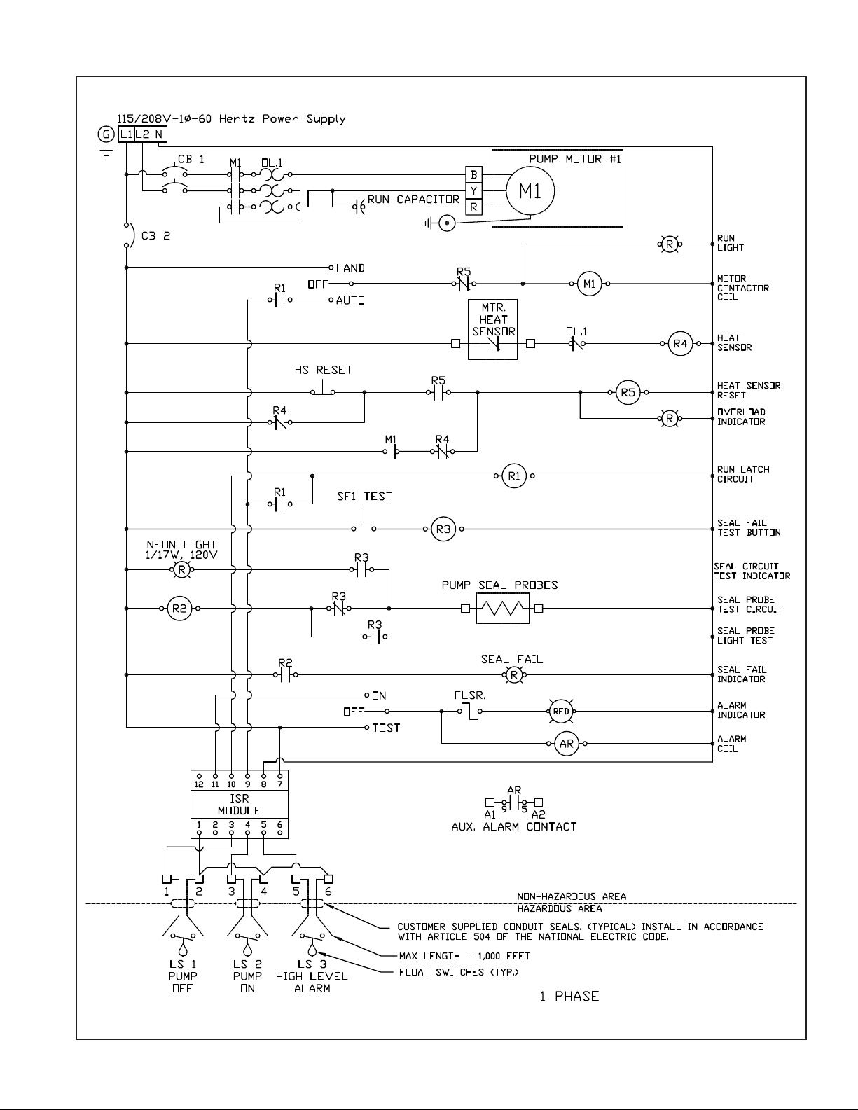
On single-phase pumps, the
white, black and red pump
leads must be connected to the
pump terminal blocks in the
panel exactly as shown on panel
markings and on the schematic.
Note: Pump will run only if leads
are connected as shown.
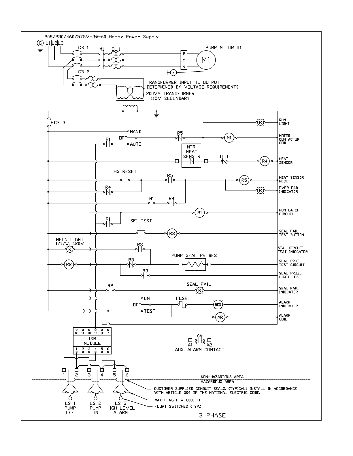
On three-phase pumps, ensure
proper phase sequence while
connecting to the overload relay
in the control panel. Incorrect
phase sequence will result in the
reverse rotation of the pump.
Note: Make sure pump ground
wire is connected to the panel
pump ground lug.
Before connecting power to
the control panel, make sure all
control switches (ex. H-O-A
switch) and protective devices
(ex. breakers) are in the Off
position. Now connect power to
main power terminal blocks or
the circuit breaker as directed
by the schematic. Control panel
must be grounded properly per
NEC and/or local codes. To
facilitate this, a ground lug is
provided on the control panel.
Panel Check List
Check List:
Check junction box for moisture.
Moisture may cause chattering of
relays/contactors.
Check O/L relay settings and
verify reset mode.
With H-O-A switch(s) in Off
position, energize power to panel.
Check voltage to the panel and at
secondary of control transformer
using a voltmeter.
Check float operation and
response of control panel
to the float operation. For
sequence of operation refer to
design specification.

3
Check full load current with
amprobe and compare it with
the nameplate rating. (Clamp
amprobe around one phase.)
With pump running, check
discharge to verify the pump
is running.
Check voltage with voltmeter
and amperage with amprobe
at overload.
Make sure H-O-A switch is left
in the Auto position after start-up
is completed.
Check the pump manuals.
Panel
Maintenance
Maintenance:
Periodicity of the maintenance
schedule will vary with operating
and environmental conditions. It
will also vary with the specific
type of control supplied. This list
is a guide only.
Exercise breaker through one
cycle. Be careful not to over
exercise as the breaker is not
a switching device. Excessive
operations tend to affect the trip
curve of the breaker.
Check contactors and relays for
excessive humming. This can be
accomplished by turning pumps
on and off in the Hand and Off
modes with H-O-A switch.
Check bulbs in all fixtures.
Check continuity through the
control fuses.
Check voltage at primary and
secondary of control transformer.
Check the pump full load amps.
If applicable, check the single-
phase start relay by using an
amprobe around the red wire
(start winding). Amprobe should
display a very brisk action from
zero to locked rotor and back to
operating load. This action occurs
on pump start and the action
must show no lazy movement.
For further details, consult
the factory.
Check junction boxes for
moisture. Moisture may
cause chattering of the relays
and contactors.
If enclosure has a door gasket,
check door gasket for integrity.
This can be a visual inspection.
Check labels to verify they have
not been damaged.
Lubricate enclosure hinges.
Pull floats and check for proper
operation and ensure there is no
foreign buildup on them.
Panel Spare
Parts List
The following is a list of
recommended spare parts;
however, conditions of service
vary significantly and a general
list may not in its entirety be
applicable to a given installation.
1. Fuses for control
transformer(s) primary
and secondary.
2. Intrinsically safe relay.
3. Contactor.
4. Bulbs for alarm lights.
Conditions That Void
UL Listing:
The intrinsically safe control
panel as manufactured per the
Hydromatic®standard is a UL
Listed device. In order to protect
the UL Listing, it is imperative
that no component, layout,
wiring or barrier changes be
made without prior consent of
the factory.
Panel
Troubleshooting
1. Pump does not run in
Hand position.
a. Check pump circuit breaker,
control circuit breaker and
control fuses for tripped or
blown condition.
b. Check overload relay to see
if it is tripped. Reset relay
if tripped.
c. If supplied, check heat
sensor reset to verify
thermal overload of motor
has not tripped.
d. Check wiring of pump to
control panel. It should
agree with the schematic.
2. Pump does not run in
Auto position.
a. Check items a. through d.
per Item #1 above.
b. Floats may not be hanging
free or may have a buildup.
Pump the level down with
the selector switch on Hand,
so floats can be observed.
c. Floats may be miswired
to control panel. Check
float wiring and hookup by
referring to the schematic.
If the start and stop floats
are hooked in reverse, pump
will short cycle and will not
pump the level down.
d. The floats or the alternator
could be defective. Check
the floats with a continuity
check and operate panel
through a few cycles to
check alternator operation.
e. Is water level sufficiently
high in wet well to activate
appropriate floats?
f. Check electrical operation
of each float. Disconnect
the main power, then
disconnect each float

one at a time and check
operation with an ohmmeter
by manually raising and
lowering the float.
3. Pump runs but red run light
does not energize.
a. Check the run light.
b. Check for loose wire at light
or in panel.
4. Pump runs but does not
pump down the wet well.
a. Pump rotation may be
wrong. Wiring of pump
to control panel may be
reverse sequenced.
b. Impeller may be dragging
in volute due to solids.
High ampere draw would
identify this.
c. Refer to the pump manual
for other possibilities such
as closed discharge gate
valve, etc.
5. Severe humming/
chattering of contactors
and control relays.
a. There may be low voltage.
Check voltage at primary
and secondary of control
transformer by using
a voltmeter.
This low voltage condition
may even cause severe
chattering and burn-up of
relays. The utility needs to
increase voltage.
b. Contactor may have dust
around magnet of coil
structure. Clean and/or dry
as required.
c. Check voltage to the control
panel. Contactors require
a minimum of 85% of full
voltage to pull in without
chatter. If the problem is
a chronic one, measure
voltage with recorder on a
24 hour basis.
d. Make sure floats are located
away from any turbulence.
4
e. Dry out the junction box
(if furnished); moisture in
the junction box will tend
to cause the intrinsically
safe relays to energize
intermittently.
6. Nuisance tripping of
overload on motor starters
or circuit breakers.
a. Check all reset buttons and
tripped breakers.
b. Check pump amp draw with
amprobe and compare to
nameplate amps on pump.
c. The impeller may be locked
up due to excessive debris
or solids.
d. Possible motor failure (fault
on windings).
e. Pump may be miswired to
terminal block.
7. Short cycling pump.
a. Check float controls.
8. Run light stays on.
a. Selector switch may be in
the Hand position.
9. Red seal failure light
comes on.
a. Pump seal has failed and
allowed contaminant
to enter pump housing.
Refer to pump manual for
appropriate action.
10.Test for blown fuse.
a. With main power turned
off, check fuses with
V-O-M set on ohm scale.

5

6

THIS PAGE INTENTIONALLY LEFT BLANK

740 EAST 9TH STREET 490 PINEBUSH ROAD, UNIT #4
ASHLAND, OHIO, USA 44805 CAMBRIDGE, ONTARIO, CANADA N1T 0A5
419-289-1144 800-363-PUMP
WWW.HYDROMATIC.COM
Warranty Rev. 12/13
STANDARD LIMITED WARRANTY
Pentair Hydromatic® warrants its products against defects in material and workmanship for a period of 12 months
from the date of shipment from Pentair Hydromatic or 18 months from the manufacturing date, whichever
occurs first – provided that such products are used in compliance with the requirements of the Pentair Hydromatic
catalog and technical manuals for use in pumping raw sewage, municipal wastewater or similar, abrasive-free,
noncorrosive liquids.
During the warranty period and subject to the conditions set forth, Pentair Hydromatic, at its discretion, will repair
or replace to the original user, the parts that prove defective in materials and workmanship. Pentair Hydromatic
reserves the right to change or improve its products or any portions thereof without being obligated to provide such
a change or improvement for prior sold and/or shipped units.
Start-up reports and electrical schematics may be required to support warranty claims. Submit at the time of start up
through the Pentair Hydromatic website: http://forms.pentairliterature.com/startupform/startupform.asp?type=h.
Warranty is effective only if Pentair Hydromatic authorized control panels are used. All seal fail and heat sensing
devices must be hooked up, functional and monitored or this warranty will be void. Pentair Hydromatic will cover
only the lower seal and labor thereof for all dual seal pumps. Under no circumstance will Pentair Hydromatic be
responsible for the cost of field labor, travel expenses, rented equipment, removal/reinstallation costs or freight
expenses to and from the factory or an authorized Pentair Hydromatic service facility.
This limited warranty will not apply: (a) to defects or malfunctions resulting from failure to properly install, operate or
maintain the unit in accordance with the printed instructions provided; (b) to failures resulting from abuse, accident
or negligence; (c) to normal maintenance services and parts used in connection with such service; (d) to units that
are not installed in accordance with applicable local codes, ordinances and good trade practices; (e) if the unit is
moved from its original installation location; (f) if unit is used for purposes other than for what it is designed and
manufactured; (g) to any unit that has been repaired or altered by anyone other than Pentair Hydromatic or an
authorized Pentair Hydromatic service provider; (h) to any unit that has been repaired using non factory specified/
OEM parts.
Warranty Exclusions: PENTAIR HYDROMATIC MAKES NO EXPRESS OR IMPLIED WARRANTIES THAT EXTEND
BEYOND THE DESCRIPTION ON THE FACE HEREOF. PENTAIR HYDROMATIC SPECIFICALLY DISCLAIMS THE
IMPLIED WARRANTIES OF MERCHANTABILITY AND FITNESS FOR ANY PARTICULAR PURPOSE.
Liability Limitation: IN NO EVENT SHALL PENTAIR HYDROMATIC BE LIABLE OR RESPONSIBLE FOR
CONSEQUENTIAL, INCIDENTAL OR SPECIAL DAMAGES RESULTING FROM OR RELATED IN ANY MANNER TO
ANY PENTAIR HYDROMATIC PRODUCT OR PARTS THEREOF. PERSONAL INJURY AND/OR PROPERTY DAMAGE
MAY RESULT FROM IMPROPER INSTALLATION. PENTAIR HYDROMATIC DISCLAIMS ALL LIABILITY, INCLUDING
LIABILITY UNDER THIS WARRANTY, FOR IMPROPER INSTALLATION. PENTAIR HYDROMATIC RECOMMENDS
INSTALLATION BY PROFESSIONALS.
Some states do not permit some or all of the above warranty limitations or the exclusion or limitation of incidental or
consequential damages and therefore such limitations may not apply to you. No warranties or representations at any
time made by any representatives of Pentair Hydromatic shall vary or expand the provision hereof.
Table of contents
Popular Touch Panel manuals by other brands

Nuvo
Nuvo NV-CTP36-V2 user guide

Bongshin
Bongshin BS-3520 instruction manual

Power-Genex
Power-Genex LSB-3 Series Instructions and operating manual

Tyco Electronics
Tyco Electronics Elo Touch 1000 Series user guide

Kessler-Ellis Products
Kessler-Ellis Products INTELLECT-69PM2 Installation & operating instructions

STS
STS 300 Series Installation and operating instructions

Advantech
Advantech PPC-6121 Disassembly instructions

Intel
Intel TPC-1770 user manual

National Instruments
National Instruments TPC-2515 user manual

WIKA
WIKA A-RB-1 operating instructions

Heisei
Heisei HPC FF Series user manual

Beijer Electronics
Beijer Electronics X2 pro 21-B2 Hardware and installation manual