2352 Walsh Ave. Santa Clara, CA 95051. U. S. A. Tel.: (408) 748-9100, Fax: (408) 748-9111 www.analogtechnologies.com
Copyrights 2000 – 2013, Analog Technologies, Inc. All Rights Reserved. 5
nalog Technologies
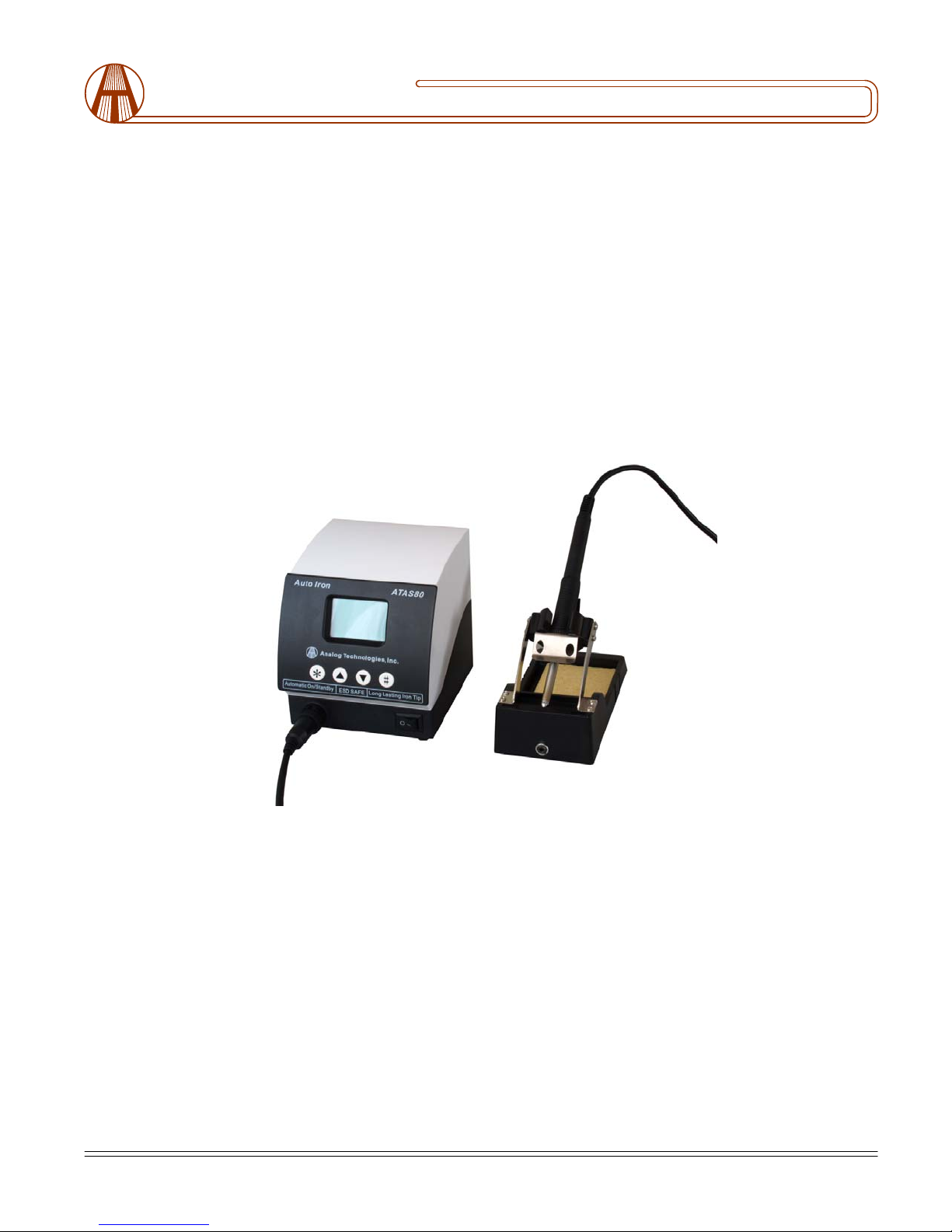
Auto Soldering Station Instructional Manual
ATAS80
V. INSTRUCTIONS FOR THE FUNCTION SETTINGS
A. Password setting:
1. press ‘*’ button to enter into ‘password setting’ mode
2. press ‘#’ to confirm
3. press ‘▲’ ‘▼’ to set the password
4. Press ‘#’ to confirm and enter the unit into locked status.
B. Release locked status:
1. press ‘*’ to enter into ‘password setting’
2. press ‘*’ ‘▼’, meantime press ‘#’ for one second
3. release the button ‘#’ and the password will be released
C. Temperature setting:
1. press ‘*’ button twice to enter into ‘temperature setting’
2. press ‘#’ to confirm
3. press ‘▲’ ‘▼’ to set the temperature
4. press the ‘#’ to confirm
D. Sleep temperature setting
1. press ‘*’ button three times to enter into ‘sleep temperature setting’
2. press ‘#’ to confirm
3. press ‘▲’ ‘▼’ to set sleep temperature
E. Sleep time setting
1. press ‘*’ button four times to enter into ‘sleep time setting’
2. press ‘#’ to confirm
3. press ‘▲’ ‘▼’ to set the required value
4. press ‘#’ to confirm
Note: When you will not be using your soldering unit, remember to put the soldering handle into the iron holder. When it
reaches the preset sleep time, the temperature will fall automatically to the set sleep temperature. When you are again ready
to work, just pick up the soldering handle from the iron holder. The main body will wake up and enter into working status
mode.