Vitronics Soltec XPM3m Product manual

Technical Reference Manual-XPM3m Revision Date:August 2014
XPM3m
Reflow Soldering Systems
Original Instructions
Technical Reference Manual
ITW ELECTRONICS (SUZHOU) Co. Ltd.
Visit address Workshop II, 858 Zhujiang Road, Suzhou New District, China 215129
Telephone: +86-512-6841-3378
Fax: +86-512-6841-1711

Technical Reference Manual-XPM3m Revision Date: August 2014
TABLE OF CONTENTS
TABLE OF CONTENTS _______________________________________________________________ 2
PURPOSE OF THIS MANUAL & WHO SHOULD USE IT ____________________________________ 4
CONTROL PANEL SYMBOLS __________________________________________________________ 5
GLOSSARY OF TERMS GLOSSARY OF TERMS & MEASUREMENT CONVERSIONS ____________ 6
MEASUREMENT CONVERSIONS ------------------------------------------------------------------------------------------------------------------ 7
CONTROL SYSTEM OPERATION _______________________________________________________ 8
OVEN CONTROL SYSTEM OVERVIEW ---------------------------------------------------------------------------------------------------------- 8
POWER DISTRIBUTION OVERVIEW -------------------------------------------------------------------------------------------------------------- 9
COMPUTER AND CONTROLLER OVERVIEW ----------------------------------------------------------------------------------------------- 10
CONVEYOR OVERVIEW ----------------------------------------------------------------------------------------------------------------------------- 11
FAN CONTROL OVERVIEW ------------------------------------------------------------------------------------------------------------------------ 12
HEAT CONTROL OVERVIEW ---------------------------------------------------------------------------------------------------------------------- 13
HEATING CELL DESCRIPTION ________________________________________________________ 15
XPM3m HEATING CELL CROSS-SECTION --------------------------------------------------------------------------------------------------- 15
XPM3m OVEN CELL ARRANGEMENT --------------------------------------------------------------------------------------------------------- 16
XPM3m HEATING CELL DESCRIPTION ------------------------------------------------------------------------------------------------------- 17
TROUBLESHOOTING _______________________________________________________________ 18
GENERAL TROUBLESHOOTING ----------------------------------------------------------------------------------------------------------------- 18
HEATER TESTING PROCEDURE ----------------------------------------------------------------------------------------------------------------- 20
THERMOCOUPLES ----------------------------------------------------------------------------------------------------------------------------------- 24
HEATER REMOVE AND REPLACE PROCEDURES ---------------------------------------------------------------------------------------- 25
CELL FAN MOTORS ---------------------------------------------------------------------------------------------------------------------------------- 29
CONVEYOR _______________________________________________________________________ 36
CONVEYOR TYPES ----------------------------------------------------------------------------------------------------------------------------------- 36
EDGE / RAIL CONVEYOR SYSTEM-------------------------------------------------------------------------------------------------------------- 36
MESH BELT CONVEYOR SYSTEM -------------------------------------------------------------------------------------------------------------- 37
COMBINATION CONVEYOR SYSTEM ---------------------------------------------------------------------------------------------------------- 37
EDGE RAIL WITH EXTRUDED CENTER SUPPORT SYSTEM (XCS) ----------------------------------------------------------------- 38
CONVEYOR BELT, CHAIN & RAIL SERVICE ------------------------------------------------------------------------------------------------- 39
REMOVE AND REPLACE CONVEYOR BELT------------------------------------------------------------------------------------------------- 39
CONVEYOR DRIVE SYSTEM _________________________________________________________ 41
DRIVE MOTOR SERVICE & REPLACEMENT ------------------------------------------------------------------------------------------------- 43
REMOVE AND REPLACE CONVEYOR RAILS AND CHAINS ---------------------------------------------------------------------------- 43
ELECTRICAL POWER & COMPUTER __________________________________________________ 45
ELECTRO - STATIC DISCHARGE PROCEDURES ( ESD) -------------------------------------------------------------------------------- 45
A.C. & D.C. POWER SUPPLIES --------------------------------------------------------------------------------------------------------------- 47
OVEN CONTROLLER ________________________________________________________________ 49
ADDRESSING DIP SWITCHES ON DI BOARD ----------------------------------------------------------------------------------------------- 50
ADDRESSING LINKS ON AI BOARD ------------------------------------------------------------------------------------------------------------ 50
CONTROLLER STATUS ----------------------------------------------------------------------------------------------------------------------------- 50
CONTROLLER OUTPUTS (INPUT/OUTPUT BOARD) -------------------------------------------------------------------------------------- 52
COMPUTER SYSTEM--------------------------------------------------------------------------------------------------------------------------------- 53
CONTROL CIRCUIT ----------------------------------------------------------------------------------------------------------------------------------- 53
ELECTRICAL GROUNDING OF OVEN ---------------------------------------------------------------------------------------------------------- 54
ASSOCIATED SUBSYSTEMS _________________________________________________________ 55
TRUE N2 / AIR SWITCHING ------------------------------------------------------------------------------------------------------------------------ 55
BATTERY BACK-UP FOR PC, CONTROLLER, CONVEYOR, AND HOOD LIFTS ------------------------------------------------- 56
PRODUCT TRACKING AND ALARM ------------------------------------------------------------------------------------------------------------- 56
COMPUTER CONTROLLED EDGE-RAIL LUBRICATION --------------------------------------------------------------------------------- 57
AUTO CHAIN LUBE TANK/PUMP ASSY -------------------------------------------------------------------------------------------------------- 58
BOARD SUPPORT ------------------------------------------------------------------------------------------------------------------------------------- 60
CONTROLLED EXHAUST SYSTEM (AIR ONLY OR OVENS EQUIPPED WITH AIR SWITCHING) ------------------------- 61

Technical Reference Manual-XPM3m Revision Date: August 2014
INDIVIDUAL CELL INLETS -------------------------------------------------------------------------------------------------------------------------- 61
FLUX EVACUATION SYSTEM (FLUX FLOW CONTROLTM ) --------------------------------------------------------------------------- 63
FUNCTION OF THE FLUX EVACUATION SYSTEM (FLUX FLOW CONTROLTM ) ------------------------------------------------ 64
HOODLIFTS ---------------------------------------------------------------------------------------------------------------------------------------------- 66
THREE ACTUATOR SYSTEM ---------------------------------------------------------------------------------------------------------------------- 72
INDEPENDENT ALARM SCANNER OVER-TEMP & ALARM/SHUTDOWN ---------------------------------------------------------- 73
INDIVIDUAL CELL SENSING ----------------------------------------------------------------------------------------------------------------------- 74
HEATER CELL OVER-TEMPERATURE SWITCHES ---------------------------------------------------------------------------------------- 77
ON-BOARD OXYGEN (O2) ANALYZER -------------------------------------------------------------------------------------------------------- 80
COOLING SYSTEMS ________________________________________________________________ 81
XPM3m AMBIENT AIR COOLING – AC1 OPTION ------------------------------------------------------------------------------------------- 81
XPM3m HEAT EXCHANGER ASSEMBLIES--------------------------------------------------------------------------------------------------- 82
TUBE TYPE HEAT EXCHANGER ----------------------------------------------------------------------------------------------------------------- 83
FIN & TUBE TYPE HEAT EXCHANGER -------------------------------------------------------------------------------------------------------- 83
XPM3m BASIC COOLING PACKAGE – EC1 OPTION ------------------------------------------------------------------------------------- 84
BASIC COOLING PACKAGE COOLANT FLOW DIAGRAM – EC1 OPTION --------------------------------------------------------- 85
XPM3m EC2 COOLING PACKAGE --------------------------------------------------------------------------------------------------------------- 86
FLOW DIAGRAM – EC2 OPTION ----------------------------------------------------------------------------------------------------------------- 88
XPM3m ENHANCED COOLING PACKAGE EC-1 -------------------------------------------------------------------------------------------- 89
ENHANCED COOLING PACKAGE EC-1 FLOW DIAGRAM ------------------------------------------------------------------------------- 90
XPM3m ENHANCED COOLING PACKAGE EC-2 -------------------------------------------------------------------------------------------- 91
ENHANCED COOLING PACKAGE EC-2 FLOW DIAGRAM ------------------------------------------------------------------------------- 92
XPM3m ENHANCED COOLING PACKAGE EC-3 -------------------------------------------------------------------------------------------- 92
ENHANCED COOLING PACKAGE EC-3 FLOW DIAGRAM ------------------------------------------------------------------------------- 93
XPM3m EXTERNAL COOLANT SUPPLY OPERATION: ----------------------------------------------------------------------------------- 95
RAIL ADJUST: _____________________________________________________________________ 96
MANUAL RAIL ADJUST ------------------------------------------------------------------------------------------------------------------------------ 96
AUTO RAIL ADJUST ---------------------------------------------------------------------------------------------------------------------------------- 98
TROUBLESHOOTING: ----------------------------------------------------------------------------------------------------------------------------- 101
DC DRIVE CALIBRATION (RAIL WIDTH ONLY) ------------------------------------------------------------------------------------------ 103
SMEMA INTERFACE -------------------------------------------------------------------------------------------------------------------------------- 105
TEMPERATURE PROFILE PLOTTING (PRECISION PROFILING) ------------------------------------------------------------------- 108

Technical Reference Manual-XPM3m Revision Date: August 2014
PURPOSE OF THIS MANUAL & WHO SHOULD USE IT
This manual is intended to meet the needs of service personnel responsible for the regular service of Vitronics
Soltec Reflow Ovens. Vitronics Soltec does not consider this manual a specification for Vitronics Soltec products or
any components contained in those products and reserves the right to change information contained in this manual
without notification.
This manual is intended to be a reference. Some of the topics explain manufacturing and assembly methods and
practices; however, many topics deal with specific service information and methods. Hopefully, insight will be
provided about the various sub-systems of the electrical control system to allow quick identification of problems and
possible solutions.
IMPROPER SAFETY PRECAUTIONS OR UNSAFE WORK METHODS MAY RESULT IN SERIOUS INJURY!
ATTENTION
This Manual is NOT INTENDED as a substitute for proper technical training or educational
background in the various technologies used in reflow ovens.
This manual is for service of Vitronics Soltec ovens by Trained Qualified Personnel. An appropriate
understanding and use of safety procedures when working on and around the oven is NECESSARY.
Caution
The following conditions may be encountered when working on any reflow oven:
High Temperature areas (up to 350o C)
High Voltage areas (up to 480 VAC)
High Current areas (up to 200 Amps)
Moving Mechanical Parts and Systems
Heavy Components
Sensitive Electronic Components
Some people who might use this manual are:
Vitronics Soltec service technicians
Customer service technicians
Customer facilities maintenance personnel
Technical operators

Technical Reference Manual-XPM3m Revision Date: August 2014
CONTROL PANEL SYMBOLS
OPERATOR CONTROL STATION
Use Caution
NOTICE
WHEN CONTROL POWER IS INTERUPTED, PARTS OF THE OVEN ARE ELECTRICALLY
POWERED AND DANGEREROUS TO PERSONNEL!
SELECTOR SWITCH
ADJUSTS RAIL
IN or OUT
KEY SWITCH RAISES
AND LOWERS THE
OVEN HOOD

Technical Reference Manual-XPM3m Revision Date: August 2014
GLOSSARY OF TERMS GLOSSARY OF TERMS & MEASUREMENT CONVERSIONS
999 º C Indicates an open thermocouple or thermocouple connection.
Actuator Used to raise and lower the top section of the oven.
AI Analog Input board. One of the boards in the Oven internal control unit.
Antistatic Device to inhibit the generation and instantaneous dissipation of static electricity.
Control Ladder Oven electrical schematic which show the relationship of all electrical circuits the oven controller
and to each other.
DC Drive An electronic power amplifier used to control the speed of DC motors.
E-stop Emergency stop.
EPO_________ Emergency Power Off
Encoder The electronic mechanism that supplies feedback information to the oven controller on how fast the
conveyor system is moving.
ESD Electro Static Discharge.
FNPT Female National Pipe Thread.
GPM Gallons Per Minute.
Heat slinger A set of fan blades mounted on the shaft of every cell motor. The function of a heat slinger is to
push heated air away from the motor windings and thus prevent premature motor failure.
Heater panel A large aluminum “sandwich” panel on the face of each heater cell in the oven.
Heat sink A piece of metal generally used to dissipate heat from some device.
ICB Inter Cell Baffle. These are pieces of metal used to help increase zone definition within the Oven
process tunnel.
Interlocks Optional Switches used to ensure that the access panels are closed on the Oven.
Inverter Variable Frequency Drive used to control the speed of the convection fan motors in the Oven.
IR Infrared, refers to a component of the heat which is generated in an oven.
LED Light Emitting Diode.
DI Digital Input Board. One of the boards in the Oven internal control unit.
MNPT Male National Pipe Thread.
Offload The end of the oven where product exits the tunnel.
Ohmmeter A precision instrument used to check and display the value of electrical resistances in Ohms.
Onload The end of the oven onto which product is placed.
Phase One leg of three-phase power.
Plenum A large (or elongated) cavity or chamber, usually in ductwork.
Preheat t A thermal area inside a Vitronics Soltec Reflow oven.
Recipe A part of the Vitronics Soltec software in which heater temperatures and conveyor speed are set.
Reflow A thermal area inside a Vitronics Soltec Reflow oven.
ROSCO Redundant Over-temperature Sensing and Control Option.
RTV Brand name for a silicone sealing agent used in the Reflow oven.
Set point A number used to define a particular parameter in the oven. For example, the temperatures that
are defined in a recipe are referred to as the heater set points for each heater.
Slot settings Air passages (slots) on both sides of the heater panel that can be adjusted from fully open to fully
closed. Slot settings refers to the actual opening size of these air passages.
SSR Solid State Relay
T/C ThermoCouple
OCP Oven Control Program. The software which controls the operation of the Vitronics Soltec Reflow
oven.
VCS Vitronics Soltec Control System – Oven controller consisting of the card cage / backplate, a DI
board, and one or more A.I boards
Zone An area of a Vitronics Soltec Reflow oven that is comprised of an upper and a lower cell within the
process tunnel. Usually referred to as a “heat zone” or “cooling zone”.

Technical Reference Manual-XPM3m Revision Date: August 2014
MEASUREMENT CONVERSIONS
Temperature
Length
Degrees Celsius (°C) = 5 / 9 x (°F - 32)
Centimeters (cm) = 2.54 x inches
Degrees Fahrenheit (°F) = (9 / 5 x °C) + 32
Feet (') = 3.281 x meters
Inches (") = 0.03937 x millimeters
Inches (") = 0.3937 x centimeters
Meters (m) = 0.3048 x feet
Millimeters (mm) = 25.4 x inches
Area
Volume
Centimeters2 = 6.452 x inches2
Centimeters3 = 1000000 x meters3
Inches2 = 0.155 x centimeters2
Centimeters3 = 16.387 x inches3
Feet2 = 10.76 x meters2
feet3 = 0.161 x Imperial gallons
Meters2 = 0.0929 x feet2
feet3 = 35.31 x meters3
feet3 = 0.134 x US gallons
inches3 = 0.061 x centimeters3
inches3 = 0.061 x milliliters (ml)
inches3 = 1728 x feet3
Imperial gallons = 0.833 x US gallons
Imperial gallons (gal) = 0.22 x liters (l)
Liters (l) = 1000 x meters3
Liters (l) = 3.7854 x US gallons (gal)
Liters (l) = 4.55 x Imperial gallons (gal)
Liters (l) = 0.001 x milliliters (ml)
meters3 = 0.00455 x Imperial gallons
meters3 = 0.02832 x feet3
meters3 = 0.00379 x US gallons
US gallons (gal) = 0.264 x liters (l)
US gallons = 1.2012 x Imperial gallons
Pressure
Volumetric flow rates
Bar = 1.01325 x atmosphere (ATM)
Imperial gallons / minute = 0.1035 x feet3 / hour
Kilograms / meter2 (kg/m2) = 10332.3 x atmosphere
(ATM)
Imperial gallons / minute = 220.06 x meters3 / Min
Kilograms / centimeter2 = 0.0703 x pounds / inch2
(psi)
liters3 / second = 0.06308 x US gallons / minute
KiloPascals (KPa) = 101325 x atmosphere (ATM)
meters3 / minute = 0.00006 x centimeters3 / second
Kilograms / meter2 (kg/m2) = 703.07 x pounds / inch2
(psi)
meters3 / hour = 0.02832 x feet3 / hour
millimeters mercury (mm Hg) = 1 x Torr = 760 x
atmosphere (ATM)
meters3 / hour = 0.22713 x US gallons / minute
Pounds / inch2 (psi) = 14.696 x atmosphere (ATM)
US gallons / minute = 264.18 x meters3 / minute
Pounds per square inch (psi) = 14.504 x Bar
US gallons / minute = 0.12468 x feet3 / hour

Technical Reference Manual-XPM3m Revision Date: August 2014
CONTROL SYSTEM OPERATION
OVEN CONTROL SYSTEM OVERVIEW
The Oven Control System will be divided into five parts:
Power Distribution Overview
Computer and Controller Overview
Conveyor Control Overview
Fan Control Overview
Heat Control Overview.
The following pages contain subsystem diagrams relating to those described above. When working on any part of
the oven, electrical safety measures must be observed. Adherence to local safety policies as well as lockout-
tagout ,is required. Use of the oven electrical schematics to assist in troubleshooting is recommended. Prior to
working on any of the oven subsystems please read the descriptions, review the diagrams, and become familiar
with the oven electrical schematics.
Technical Reference Manual-XPM3m Revision Date: August 2014
POWER DISTRIBUTION OVERVIEW
3-phase power supplied to the High Voltage terminals on the electrical panel is distributed to:
1) The primary terminals on the Control Transformer (T1), the secondary side of T1 is connected to the
line side of the E-stop relay (K37). T1 provides 120VAC for ALL control functions throughout the oven.
2) The line terminals of the Heater Contactor (K2),
3) To either the line terminals of the Fan Contactor (K13), the primary side of the INVERTER (if the oven
has the Fan Speed Control Option), or the three phase Fan transformer (if the three phase supply
voltage is higher than 240 volts).
CAUTION
REMEMBER, WHEN THE OVEN IS “OFF”, MANY PARTS OF THE OVEN MAY BE ELECTRICALLY
POWERED AND DANGEROUS

Technical Reference Manual-XPM3m Revision Date: August 2014
COMPUTER AND CONTROLLER OVERVIEW
Control of the oven is accomplished by:
1. A DELL compatible COMPUTER runs the Oven Control Program. The computer has a serial communication
link with the CONTROLLER on the electrical panel.
2. The CONTROLLER interprets the Computer’s requests to energize, de-energize, or modulate devices or sub-
systems within the oven, then receives or sends the necessary signals. If the required signal (in or out) is 5VDC
or less, it is handled directly by the CONTROLLER. If a 120VAC output signal is needed, the CONTROLLER
communicates with the INPUT / OUTPUT BOARD. The I/O board relays will switch the necessary power for
operation.

Technical Reference Manual-XPM3m Revision Date: August 2014
CONVEYOR OVERVIEW
The oven controller supplies an analog voltage reference signal between 0 and 10 volts to the conveyor motor
electronics to set the desired conveyor speed. The A42 board divides it in half and passes it through an Opamp to
avoid loading and signal loss issues from the resistor voltage divider before it sends it to pin 9 on the Integramotor.
The internal Integramotor electronics require a regulated power supply between 20 and 28 volts DC to operate,
otherwise the electronics indicate a fault condition and the motor will not operate. This voltage is supplied by the G5
power supply of the circuit. The internal Integramotor electronics control the motor speed based on a 0- 5VDC
reference signal that is supplied by dividing the 0-10VDC analog output voltage in half.

Technical Reference Manual-XPM3m Revision Date: August 2014
FAN CONTROL OVERVIEW
1) POWER SOURCE: 3 Phase power is provided to either the line terminals of the Fan Contactor (K13), the
primary side of the INVERTER, the 3 phase Fan transformer, or the 3-phase line filter depending on the Oven
options and Operating Voltage.
2) CONTROL ELEMENTS:
a) Fixed Fan Speed Ovens:
FAN CONTACTOR (K13) coil is energized by I/0 Board Output Relay A1-K5, K13’s contacts close, 3 phase
power is permitted to flow to/through the Fan CIRCUIT BREAKER(s). (F41 for all upper Fans & F42 for all
lower Fans) to the Fans for Full-Speed On/Off Control.
b) Ovens with Blower Speed Control: FAN CONTACTOR (K13) does not exist. I/0 Board Output Relay A1-
K18, in this case, serves as the Enable input to the INVERTER. An analog (modulated) Low Voltage D.C.
output from the CONTROLLER signals the INVERTER to vary it’s output frequency to the Fans, resulting in
variable-speed Control of the Fans.
3) FANS:
The FAN MOTORS are Open Frame, 3 Phase, 50/60 Hz, 1/6 Hp, 2800-3400 RPM @ rated frequency,
continuous duty.

Technical Reference Manual-XPM3m Revision Date: August 2014
HEAT CONTROL OVERVIEW
The electrical portion of the Heat Control System consists of three major parts:
1) POWER SOURCE:
Three Phase power is provided to the line terminals of the Heater Contactor (K2).
2) CONTROL ELEMENTS:
A) POWER DEVICES:
HEATER CONTACTOR (K2) coil is energized by I/0 Board Output Relay A1-K4, (see Interlocks, below) it’s
contacts close, three phase power is permitted to flow to the Heater CIRCUIT BREAKER(s). (Each Heater
has it’s own Circuit Breaker) and to the SSRs (one Solid State Relay for each Heater) which is the final
Heater power control element.

Technical Reference Manual-XPM3m Revision Date: August 2014
2- B) INTERLOCKS:
1) Over Temp Switch (es):
BI-metallic snap switch (es) mounted on each Cell Assembly, open when the temperature exceeds
normal operating temperature of the Cell. They are all wired in series and power the coil of K3. (K3
is not shown on this Overview) The coil of K2 is wired through the contacts of K3. When an over
temperature switch opens, voltage to the coil of K3 is lost. This will cause K2 to de-energize, and
ALL power will be removed from ALL heaters. K4 is the Heater Power Enable Relay, and the
voltage for K2 runs through K4, then K3, to K2. (K3 also signals the Controller to shut the Oven
down)
2) Heater Thermocouple (IAS Option)
A Heater mounted thermocouple connected to the Independent Alarm Scanner option. The I.A.S.
output contacts are wired in series prior to the cell over temperature switches and power to the coil
of K3. (K3 is not shown on this Overview) The coil of K2 is wired through the contacts of K3.
When an over temperature condition is sensed, the I.A.S board contacts open and voltage to the
coil of K3 is lost. This will cause K2 to de-energize, and ALL power will be removed from ALL
heaters. (K4 also signals the Controller to shut the Oven down)
3) Heater Thermocouple (Standard)
A Heater mounted thermocouple(s) to sense the temperature of the Heat Cell and connected to the
Controller for heater control.
3) HEATERS:
Each Heater Assembly has one large flat Inconel element (resistor) mounted between two aluminum plates.
Each element may be wired in series or parallel, depending on the operating voltage of the oven.
Heater Schematic
See: “Heater Element Resistance Reference Chart” under Heater Testing Procedure in this manual for
resistance values.

Technical Reference Manual-XPM3m Revision Date: August 2014
HEATING CELL DESCRIPTION
XPM3m HEATING CELL CROSS-SECTION
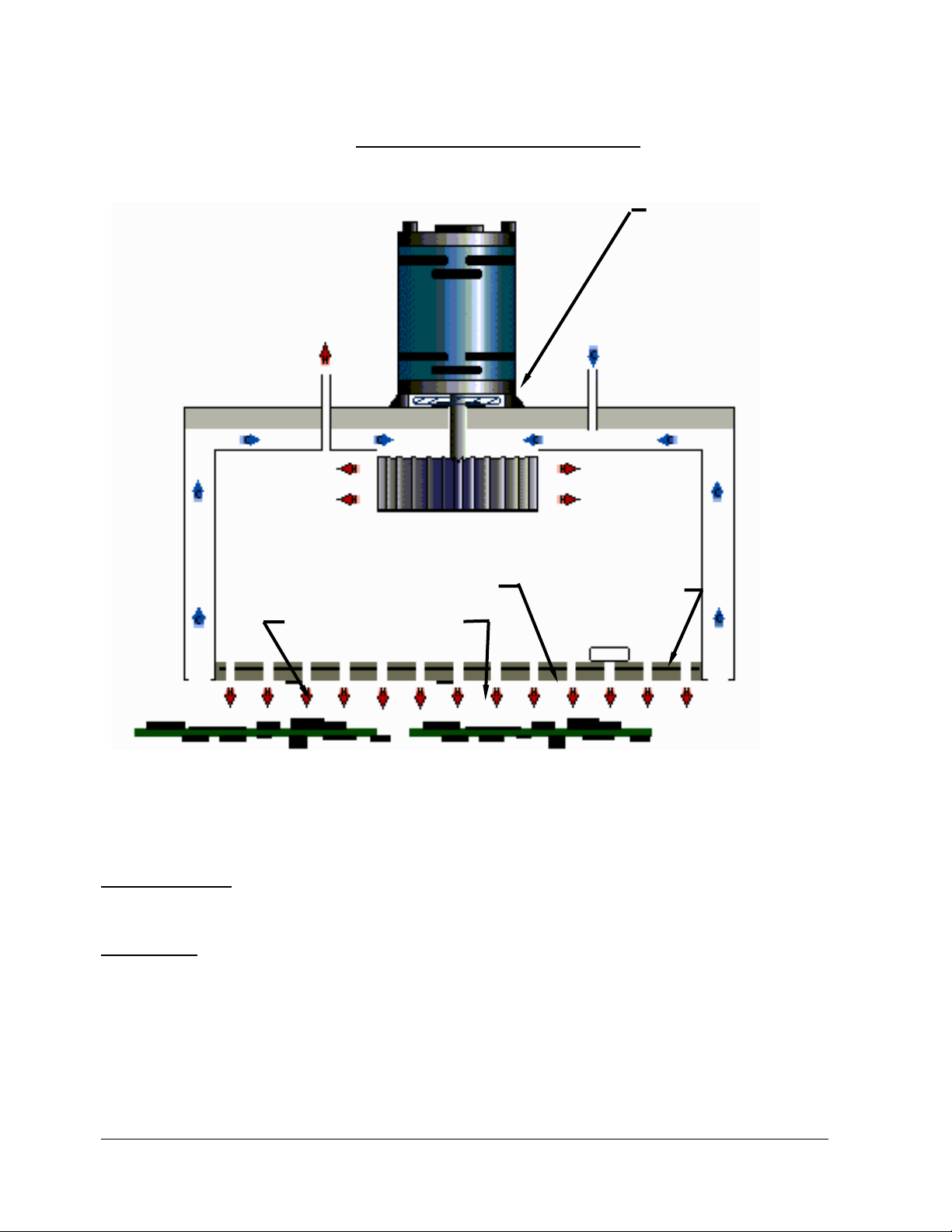
CONSTRUCTION: The heat Cells are assembled and sealed as self-contained units with the Fan Motor, and Over
Temperature Switch mounted and wired to terminals, and the Thermocouples (1 or 2) mounted and wired to
connectors.
OPERATION: The relatively thick heater assembly has a series of holes allowing heat transfer to the oven gases
passing from the Cell Cavity to the process tunnel.
Recirculation occurs through the low-pressure intakes at the sides of the Cell. These gasses are drawn into the cell
cavity, where they are passed through the heater and back into the process tunnel.
Fan Speed controls the velocity of the heated atmosphere, which influences the heat transfer to the PCB.

Technical Reference Manual-XPM3m Revision Date: August 2014
XPM3m OVEN CELL ARRANGEMENT
The cells are mounted both above and below the conveyor, as shown, forming a series of “Heat Zones”.
Each Heat Zone circulates heat primarily within itself, thereby maximizing the thermal isolation between zones.
An oven contains several heating zones (5,7,8,10, or 12) and 2, 3, or 4 cooling zones. Cooling zones are similar to
heating zones except they have no heating elements and no exhausts (only gas intakes).
A properly operating oven is an inter-dependent system. When a heater or fan malfunctions, the balance and
performance of the oven as a system may be affected. Usually, an irregularity in operation could be the result of any
one (or more) malfunctions.
Front – to – Back Recirculation slots on XPM3m
Technical Reference Manual-XPM3m Revision Date: August 2014
XPM3m HEATING CELL DESCRIPTION
HEATING CELL CROSS-SECTION
CONSTRUCTION: The heat Cells are assembled and sealed as self-contained units with the Fan Motor, and Over
Temperature Switch mounted and wired to terminals, and the Thermocouples (1 or 2) mounted and wired to
connectors.
OPERATION: The relatively thick heater assembly has a series of holes allowing heat transfer to the oven gases
passing from the Cell Cavity to the process tunnel.
Recirculation occurs through the low-pressure intakes at the sides of the Cell. These gasses are drawn into the cell
cavity, where they are passed through the heater and back into the process tunnel.
Fan Speed controls the velocity of the heated atmosphere, which influences the heat transfer to the PCB.
FAN MOTOR
INSULATION
EXHAUST
HEATER ASSEMBLY
THERMOCOUPLES
OVER TEMPERATURE
SWITCH
HEAT SLINGER
FAN BLADES
AIR OR
NITROGEN IN

Technical Reference Manual-XPM3m Revision Date: August 2014
XPM3m OVEN CELL ARRANGEMENT – SIDE-TO-SIDE RECIRCULATION
The cells are mounted both above and below the conveyor, as shown, forming a series of “Heat Zones”.
Each Heat Zone circulates heat primarily within itself, thereby maximizing the thermal isolation between zones.
An insulated exhaust plenum mounted under the Bonnet collects gases from the individual upper heat cell exhausts
and conveys the combined flow to the Plant Exhaust System.
An oven contains several heating zones (5,7,8,10, or 12) and 2, 3, or 4 cooling zones. Cooling zones are identical
to heating zones except they have no heating elements and no exhausts (only gas intakes).
A properly operating oven is an inter-dependent system. When a heater or fan malfunctions, the balance and
performance of the oven as a system may be affected. Usually, an irregularity in operation could be the result of any
one (or more) malfunctions.
TROUBLESHOOTING
INSULATED CONTROLLED
EXHAUST PLENUM
TO PLANT
EXHAUST
SYSTEM
CELL 2B
CELL 1B
CELL 3B
CELL 4T
CELL 3T
CELL 2T
CELL 1T
Zone 1

Technical Reference Manual-XPM3m Revision Date: August 2014
GENERAL TROUBLESHOOTING
For general troubleshooting of the oven systems, first to go the Help menu in the oven software. Click on the link
for Help (under Help), Then click on the link for Alarm Help. This will bring up the online troubleshooting document
that is present in the oven software.
Internet Explorer may try to block the active content in this document. It will be necessary to allow the blocked
content in order to view the complete contents of this document.

Technical Reference Manual-XPM3m Revision Date: August 2014
HEATER TESTING PROCEDURE
When a heating problem is suspected, applying this procedure should reduce the time required to eliminate a
number of items that may NOT be responsible for the problem. This will leave a much smaller number of
possibilities for consideration.
To be effective and efficient, the trouble-shooting process does not jump directly to the “answer”, but rather,
eliminates all of the possibilities one-at-time with a systematic approach, until only the “answer” remains.
SIMPLIFIED HEATER CONTROL CIRCUIT
EXPLANATION:
Each heater has a Circuit Breaker and SSR. K2 supplies two hot, high voltage conductors to the Line Side of the
Heater Circuit Breaker(s). Both of the current paths are interrupted by the Circuit Breaker when it is open or tripped.
A) On the Load Side of the Circuit Breaker, one of the conductors goes directly to the heater terminals
(HT-A, HT-B, HT-C) on the outside of the Heater Cell.
B) The other conductor is interrupted by the SSR. When the SSR operates, it conducts power from the
Circuit Breaker to the heater terminals (1, 1A, and 2) on top of the Heater Cell.
O.K. TEST: Check the heater(s) for agreement with the “HEATER ELEMENT RESISTANCE REFERENCE
CHART” after disconnecting the supply conductors at the heater terminals
(HT-A, HT-B, HT-C) on top of the Heater Cell. (This does work, however, it is time consuming, and does not check
the conductors between the Circuit Breaker / SSR and the Heater Cell.)
BEST TEST: The heater(s) and conductors can be checked at the Circuit Breakers/SSRs. Reference the
“ HEATER RESISTANCE CHECK LOCATIONS” diagram.
Table of contents
Other Vitronics Soltec Soldering Gun manuals


