Analogic bk ultrasound bkSpecto Operating and maintenance manual

Installation Procedure for bkSpecto
IG42955-03 16-01724 rev 00 1/16
Installation Procedure for bkSpecto
IMPORTANT:
This procedure must be carried out only by BK Ultrasound service personnel or their authorized
representatives. The procedure covers unpacking and set-up of the system including connecting to the
power outlet and a possible network connection.
All scanners leaving the factory are configured for mains voltage 100-240V 50/60Hz and English
language. The mains voltage does not have to be changed as the power supply accepts 100-240V
50/60Hz.
CONTENTS PAGE
1 Necessary Tools .......................................................................................................................1
2 Unpacking the System..............................................................................................................2
3 Check the fuses ........................................................................................................................3
4 Fasten the Transducer Holder Frames.....................................................................................4
5 Set-up Additional Transducer Holders (Optional – UA1371) ....................................................5
6 Set-up Side-mount basket (Optional – UA1379) ......................................................................7
7 Connectivity ..............................................................................................................................8
8 Setting Up Printer Start-up Kit (Optional – UA4104).................................................................9
9 Connect the power cord..........................................................................................................10
10 Turn On the Scanner ..............................................................................................................11
11 Electrical safety test and functional test..................................................................................11
12 Creating an User.....................................................................................................................12
13 Changing language (Optional)................................................................................................13
14 Connecting to Wi-Fi (Optional) ...............................................................................................14
15 Time and Date Settings ..........................................................................................................14
16 General information ................................................................................................................16
1 Necessary Tools
- Small thin slotted screw driver (e.g. 2mm or 3/32 in).
- Tools for electrical safety test.
- Torx #10 and #20 for printer set up.
- Torx #25 for transducer holder frame and additional transducer holders.
- Checking Procedure available in user guide.
Installation Procedure for bkSpecto
IG42955-03 16-01724 rev 00 2/16
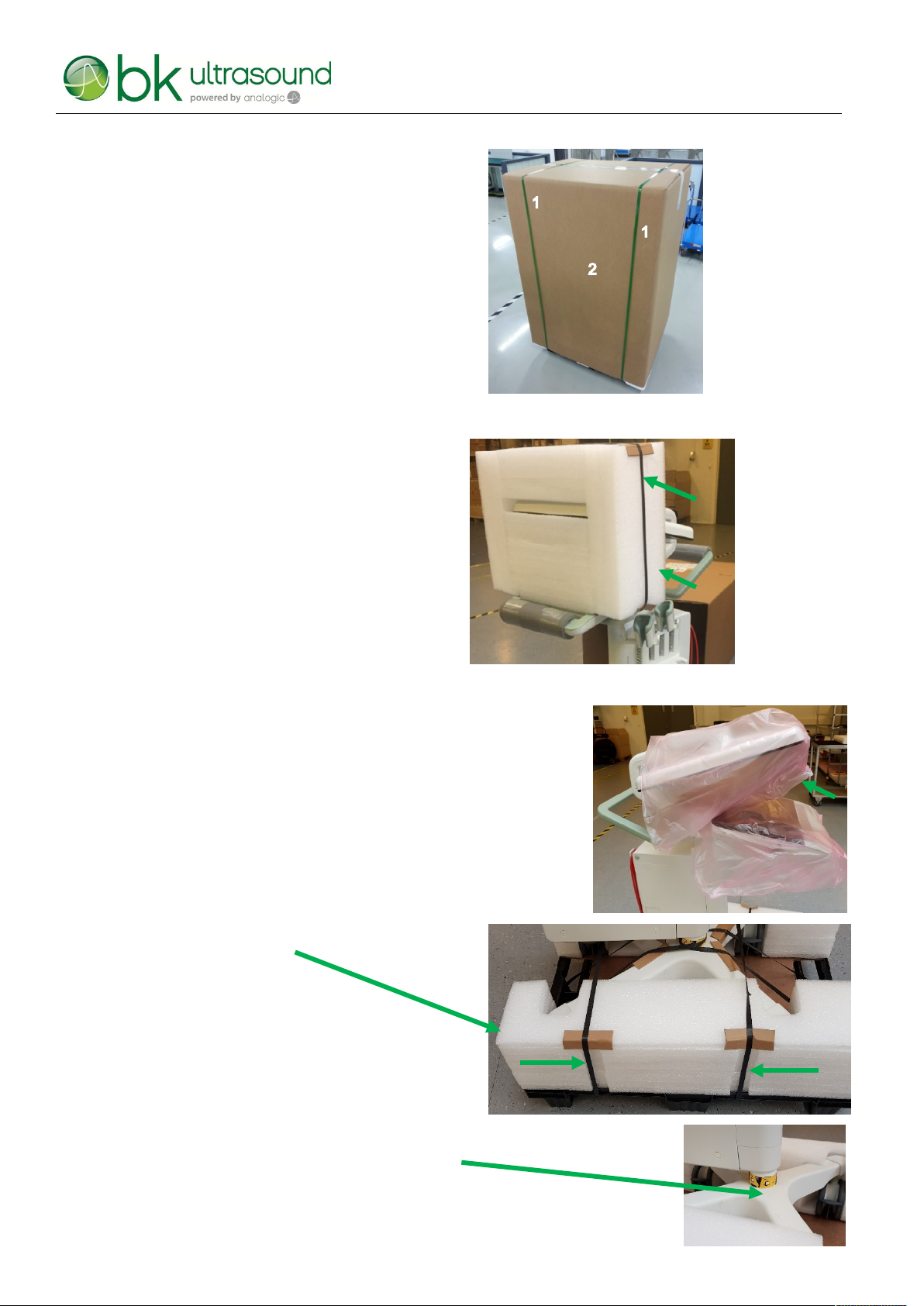
2 Unpacking the System
1. Cut and remove the two black straps.
2. Remove the cardboard.
3. Cut and remove the black strap.
4. Remove the top support.
5. Remove the plastic bag from the monitor and keyboard.
6. Remove the box from the base support (not on the picture).
7. Remove the two black straps on the base support.
8. Remove the base support.
9. Remove the tape from the wheel base assembly.
4
3
1
1
2
1
6
6

Installation Procedure for bkSpecto
IG42955-03 16-01724 rev 00 3/16
10. Remove the scanner from the pallet.
11. Empty the box from step 6.
12. Unpack the transducer holder frames from the bags.
Note:
The transducer holder frame package contains: 3 transducer holders, 1 gel holder, 2 transducer holder frame
trays, and four screws.
3 Check the fuses
1. The fuses are placed under the engine next to the power inlet. Check the fuses are correct:
Scanner Overview
Procedure
Press the black latch
(listen for a click sound)
and remove the fuse
holder.
Check the correct
fuses are used:
T4AH250V
Insert the fuses into the holder and insert the
holder into the engine again.
CAUTION:
While inserting the fuse holder a click sound will indicate that it is mounted properly.

Installation Procedure for bkSpecto
IG42955-03 16-01724 rev 00 4/16
4 Fasten the Transducer Holder Frames
The scanner comes with two transducer holder frames. One for the right side with two transducer holders and
one for the left side with one transducer holder and one gel holder. The screws used are in the zipper bag. If the
system has been bought with the optional transducer holder kit UA1371 first go to step 5Set-up Additional
Transducer Holders (Optional – UA1371).
Figure 4-1: Left transducer holder frame.
1. Fasten the frames to the scanner with 2 x M5X16 screws torx #25.

Installation Procedure for bkSpecto
IG42955-03 16-01724 rev 00 5/16
5 Set-up Additional Transducer Holders (Optional – UA1371)
UA1371 contains two additional probe holders.
Figure 5-1: UA1371 parts
Note:
Be aware the transducer bases for left and right are not identical.
1. Remove the holders by unscrewing four screws from each of the
transducer bases.
2. Separate the stiffener, transducer bases, and the frame by
removing 3 x M5X12 screws torx #25.
3. Remove the spacer.
4. Attach the new transducer base to the two metal pins on the stiffener.
2 x Transducer Base
8 x M312 screws
2 x Cup holder
2 x Elastomer holder

Installation Procedure for bkSpecto
IG42955-03 16-01724 rev 00 6/16
5. Fasten the probe holder bases to the probe holder frame and stiffener using 3 x M5X12 screws torx #25.
6. Slide the green elastomer holder inside the white cup holder.
7. Fasten the three transduce holders to the transducer bases with 4 x M3X12 screws pr. Transducer torx #10

Installation Procedure for bkSpecto
IG42955-03 16-01724 rev 00 7/16
6 Set-up Side-mount basket (Optional – UA1379)
1. Remove the two screw covers using a thin screw driver.
Scanner Overview
Procedure
Place the screw driver in the pocket, press
upwards, and pull.
The locking
mechanism is casted
into the engine cover.
Screw covers with
the two pins.
A screw cover has two pins which fit into the
engine cover as locking mechanism.
CAUTION:
Make sure not to scratch the cover with the screw driver.
Note:
The basket can also be attached other places on the engine.
2. Remove the two M4X8 screws torx#20.
3. Mount the two new plastic knobs with the two new and
longer screws from the kit.
4. Click the screw covers on the knobs.
5. It is now possible to hang the basket on the scanner.

Installation Procedure for bkSpecto
IG42955-03 16-01724 rev 00 8/16
7 Connectivity
Touch Display
The IO board on the engine behind the lid.
USB 3.0
Below the Engine
Standby
power
Switch
Mains input
and fuses
Potential
equalisation
HDMI
Out
Audio out
Mic in
LAN /
(DICOM)
USB 3.0
USB 2.0
For Pro-
duction
and
research

Installation Procedure for bkSpecto
IG42955-03 16-01724 rev 00 9/16
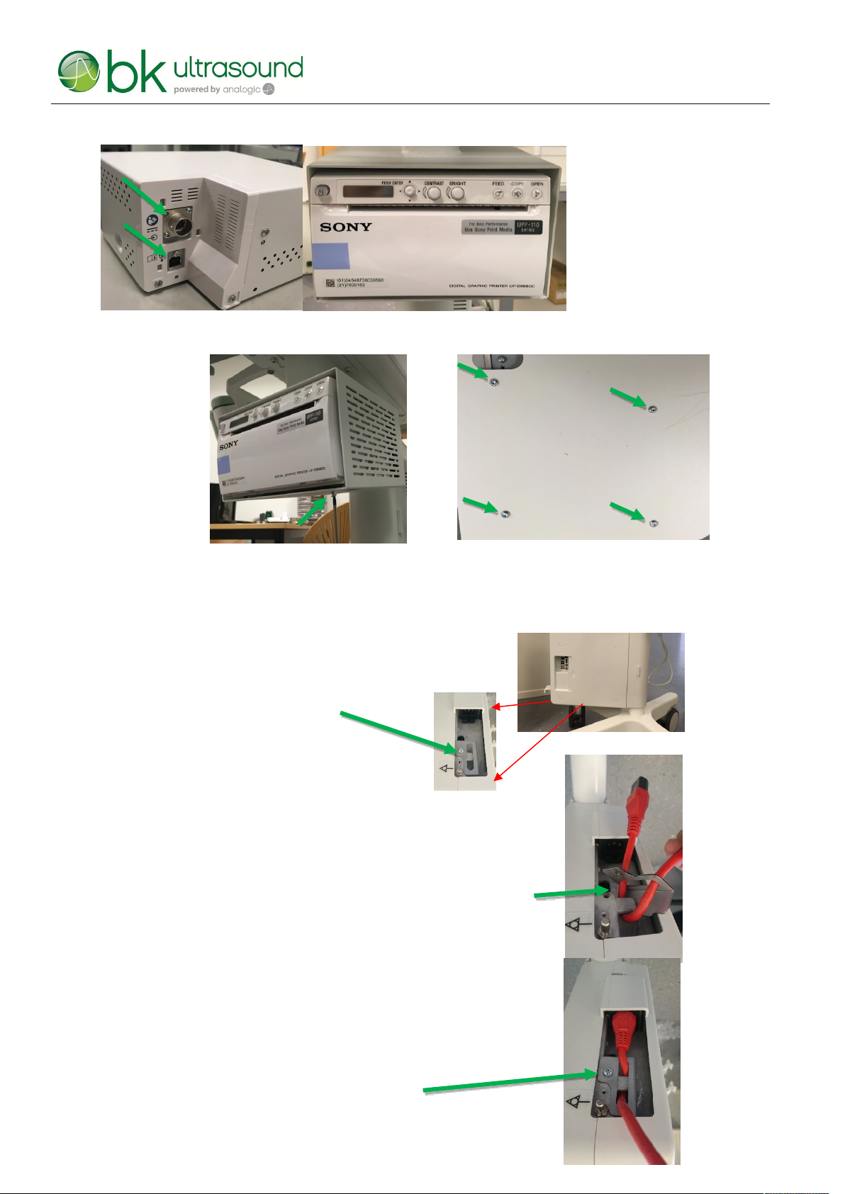
8 Setting Up Printer Start-up Kit (Optional – UA4104)
The printer is placed below the touch display in a printer holder.
1. Remove 1 screw with a torx #20 and remove the lid.
Scanner Overview
Procedure
Note:
Remember to support the cover while removing the screw
2. Cut off the zip tie.
3. Gently pull out the USB cable and the power cable.
CAUTION:
Do not pull too hard making sure not to damage the system.
4. Mount the four screws with washer head. Leave some space
for the printer holder.
CAUTION:
If the screws are fastened too much it is not possible to slide on the printer holder.
5. Slide on the printer holder and fasten the screws using the enclosed torx
key.
Installation Procedure for bkSpecto
IG42955-03 16-01724 rev 00 10/16
6. Connect the two cables to the printer and gently slide the printer into the holder.
7. Finally fasten the printer to the using four screws.
The printer is fastened from below with four screws to the printer holder.
9 Connect the power cord
1. Unscrew the screw and
remove the power restraint bracket
Insert the power cord though the long hole in the bracket
2. Put the cable “hook” in behind the metal part as shown in the picture.
3. Connect the power cord to the mains connector
4. Fasten the screw to secure the power cord
from accidently power cord dropout.
Table of contents
Other Analogic Multiplexer manuals


