Analogue Solutions CONCUSSOR User manual

ANALOGUE SOLUTIONS
CONCUSSOR e&oe (c) 12-2007
1
ANALOGUE SOLUTIONS
synthesis / percussion / sequencing / effects
modular synthesisers, modular percussion
synthesisers, rack effects, oddities
CONCUSSOR

ANALOGUE SOLUTIONS
CONCUSSOR e&oe (c) 12-2007
2
SAFETY INSTRUCTIONS
Please read carefully before using:
• Only use the correct power adaptor - 230V (or 115V whatever your country needs)
• Never handle the adaptor with wet hands
• Never excessivly bend the adaptor cable or get it trapped or place heavy objects on it. If the adaptor cable
becomes damaged, replace the adaptor.
• Ensure the unit is disconnected from the mains before moving or cleaning.
• Always disconnect the unit from the mains if there is lightning in your area.
• Ensure the unit is on a stable surface, and never place heavy objects on top of it.
• Never allow young children or animals to operate the unit or adaptor.
• Do not use excessive force when using the controls or inserting cables to the connectors.
• The unit should not be operated in the rain or near water and should not be exposed to moisture. If the unit is
brought from a cold environment to a warm one, the unit should be left to reach the ambient temperature.
• Keep Concussor away from heat sources, such as radiators, ovens, heaters etc.
• Never allow Concussor to get wet. Do not operate it near water, like pools, sinks, bathrooms etc. Do not place
beverages on or near it.
• Never open the case or attempt to make repairs. Refer any servicing to a qualified service personnel.
Preventing damage to other connected devices
Concussor modules have a very high dynamic range. It is capable of produce loud signals of very high and sub-
sonic frequencies that could blow inadequate speakers if played too loud. It is recommended that input levels to external
equipement (mixers, amp's etc.) is kept low when first connected, and then sowly increased to a userable level.
Maintenance Instructions
Any cleaning of the Concussor case should be done with a clean lint-free cloth. DO NOT USE SOLVENTS OR
CLEANERS, as this will deteriorate the exterior appearance of the equipment.

ANALOGUE SOLUTIONS
CONCUSSOR e&oe (c) 12-2007
3
About The Manual
This manual will explain all details about each module, along with some standard and more complex patching ex-
amples. With modular synths there are a near limitless range of patching possibilities. We can’t possibly tell you all the
different patches possible, so if you need further help and information there are many great resources on the web.
The manual is constantly being updated with new patching ideas and other information, so there will never be a final
version. Our web site has a copy of the latest manual freely available for download in PDF format.
Unlimted Customer Support
Owners of Concussor receive unlimited phone/fax/email support. We will do our best to help you get the best from
your system. If you have a lengthy or complex problem, it is probably best to call rather than email, as some things are
easier to explain than type.
Tel: 01384 35 36 94 International Tel: +44 1384 35 36 94
Fax: 01384 35 36 94 International Fax: +44 1384 35 36 94
www.analoguesolutions.com
56 Kingsley Road, Kingswinford, West Midlands, DY6 9RX,United Kingdom

ANALOGUE SOLUTIONS
CONCUSSOR e&oe (c) 12-2007
4
Cases & PSUs
AS0084................................................................................................ 84HP plastic case
AS1600.................................................................................................2x 84HP, 6U case

ANALOGUE SOLUTIONS
CONCUSSOR e&oe (c) 12-2007
5
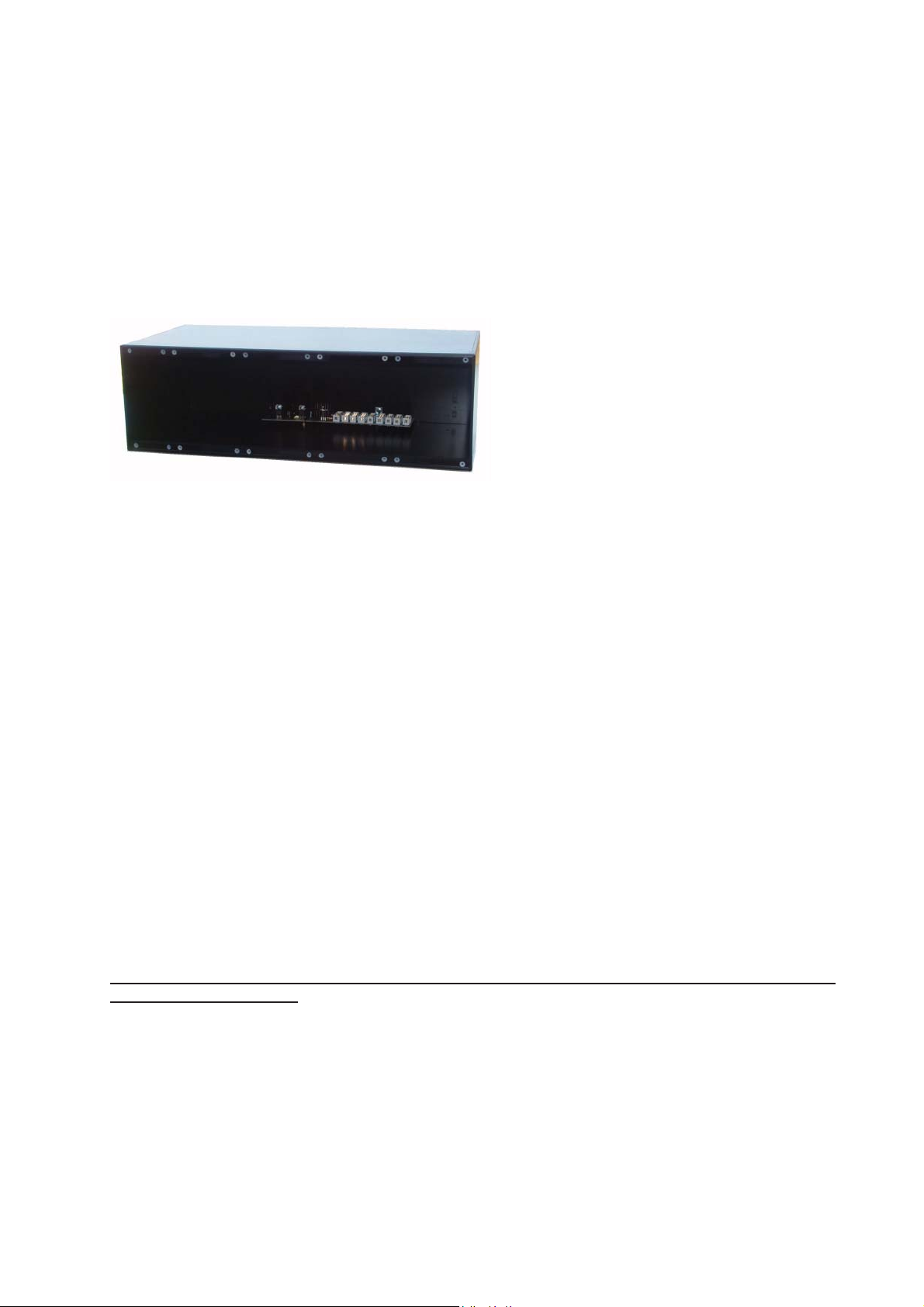
AS0084 84HP Minimodular Case
Module Power Connectors:
9x Doepfer, 3x Integrator
Power input:
12-15V AC external power supply 500mA or higher, 2.1mm DC socket.
230v mains adaptor only supplied for Euro models. 115V US adaptors are available from Noisebug.
Width:
84HP
Introduction
This is a lower cost alternative to the pricey alu-
minium style cases.
TheAS0084willtakeanycombinationofConcussor,
A100or Integratormodules withno problemsof gapsor
lining up because it does not use tapped strips.
Power Supply
The power supply board has 9 Doepfer style con-
nectors and 3 Integrator sockets. A 5V power rail is
provided for those modules that require it. It uses an external power suppy of 15VAC. This case uses 15V AC (NOT
DC!) Use a minimum of 500mA external power supply (not supplied). We can only supply 230V external adaptors with
either UK or Euro plugs.
As the power supply requires AC, it does not matter which way round you fit the connector. If you accidentally use
a 15V DC power supply, it will not cause any damage, but the system won’t work.
The case will generally supply a full set of modules unless there are too many power hungry modules.
Mounting
The AS0084 case eliminates the use of tapped strips, used in the metal case. This saves a heck of a lot of money,
but it does mean you must drill your own mounting holes.
The modules are mounted with self tapping screws into plastic mounting blocks. As plastic is not as strong as metal,
these cases are not ideal if you constantly are swapping modules around. Although this can be done many times, the
threadin the plastic screwholes can weakenwith time with constantscrewing and un-screwing. Ifyou do stripthe plastic
thread, you can use thread-lock, or fill the hole with glue,
All that is needed is to position modules in the case, mark the mounting holes, remove modules, drill pilot holes
approx 1mm to 2mm diameter, screw modules into position. This is far easier than it sounds, but if it puts you off then
pay the full cost for a metal case! (Nearly twice!).
Note: Integrator modules are a little wider than Concussor and A100, so it may not be possible to fill the case with
only Integrator modules - the total width may be too wide by say 0.5mm. This is because Integrator modules do not
fully stick to the Euro-rack standard. Their modules are just a tiny bit too wide, and they have positioned their mounting
holes in the incorrect place.
Note: do not overtighten the self tap screws otherwise you will strip the thread in the plastic.
If you are plugging in non-Concussor modules - you may void warranty as we cannot be responsible for
other manufacturer’s faults.
Rack Mounting
The AS0084 can be rack-mounted with optional rack-ears. The case is just a tiny bit over 3U in height.
Rubber Feet
The case come with four rubber feet. You can optionally fit these using the supplied M3 screws and nuts. It is best
to fit these if required before fitting any modules.

ANALOGUE SOLUTIONS
CONCUSSOR e&oe (c) 12-2007
6
Handling and Inserting Modules
Modules can be placed in any position in the rack. It is a good idea to place one module in at a time and test it before
going onto the next. This way if any module causes a problem, it can quickly be identified.
Redorblackstripeindicates
pin (wire) 1
Pin 1
16 pin power socket
(as featured on the Concussor
module, Concussor PSU, and
Integrator PSU)
16 pin ribbon power lead
- same at both ends.
When connecting the power lead
to the socket, ensure correct
orientation (stripe to pin 1), and
that none of the pins are bent.
Make sure all pins seat correctly
into the socket.
On the Concussor module, the
Integrator power socket will be
marked ‘AS-POWER’ and pin 1
is located by the word ‘STRIPE’.
Power socket as used by the Integrator
STRIPE
we CAN tell when a module is blown due to incorrect fitting of power lead. Get it right!
Some modules contain static sensitive circuitry . This circuitry is exposed when not fitted into the rack.
Whenhandling any module,try and only handleit by thefront panel. Trynot to touchany part of thecircuitry.
It is OK to handle the edge of the circuit board. Always disconnect the rack power supply from the mains
when inserting modules or doing anything inside the rack. Note, just a few of the Concussor modules have
thepowersocket up-side-down. This should notcause any confusion as thepower cable is always supplied
fitted when buying a Concussor module.
Concussor modules feature both Doepfer and Integrator power sockets. Please state which system you
intended to use the Concussor module with so we can supply the correct power lead. Default is Doepfer.
The Concussor power supply also features sockets for both. If you run out of sockets on the power supply
board, you can purchase ‘bus power cables’ from us. These are ribbon power leads that feature multiple
power sockets - buss cables - enabling many modules to be plugged into only one power supply socket.
It is up to you to connedt modules to PSUs correctly. Whether you have bought one of our cases, power
boards or adaptor leads, we cannot guarantee your handy work! Also we certainly won’t guarantee our modules if you
are mixing and matching manufacters. To those who have bought our adaptor cables to connect Integrator modules to
a Doepfer PSU, or vice versa:- Our adaptor cables are fully tested. However, we do not guarantee the modules or the
power supply under ANY circumstance (including faulty cable).
Please refer to the following diagrams for details of connecting the power lead to the power sockets:

ANALOGUE SOLUTIONS
CONCUSSOR e&oe (c) 12-2007
7
STRIPE
Pin 1
16 pin IDC header
(as featured on Concussor
or Doepfer PSU/Bus board)
- this will be 14 pin on the
Concussor module.
Red or black stripe
indicates pin (wire)
14 pin IDC socket at module end.
14 pin IDC socket at Doepfer PSU/Bus end.
12 pin IDC socket at Concussor PSU end.
When connecting the power
lead to the socket, ensure
correct orientation (stripe to
pin 1). When the socket has
more holes than the header
has pins, make sure the pin
1s of the connector line up.
On the Concussor module,
the Doepfer power socket
will be marked ‘DOEPFER’
and pin 1 is located by the
word ‘STRIPE’.
Power socket as used by Doepfer.
The red stripe on the cable indicates pin 1 (-12V). You may think of pin 1 as being at the top, but Doepfer
have place it at the bottom, so Doepfer sockets appear UP SIDE DOWN!
Each power line (+12, -12, & +5) has 2 pairs of pins. The Ground (GND) line uses 2 pairs.
Note: With Doepfer systems, +5 power is an option. Some Concussor modules require +5, so check you
have this option installed! With Concussor power supplys, +5 is always supplied as standard.
+5
+12
GND
-12
Doepfer socket as it appears on
the bus board.
The stripe on the cable MUST go
to pin 1 (-12)
The socker on the lead may have more holes than there are pins on the PCB. On allConcussor modules, there are
12 pins on the board, and either 14 or 16 holes in the socket. The same applies though - match the striped end of the
lead/socket to the work ‘STRIPE’ on the board. In this case the socket will over hang the board on the opposite end to
the stripe end.
Warning:
The pin outs of our sockets are the same as Doepfer and Integrator. So if you plug
them in correctly you will have no problems. Do not expect our sockets to necessarily look
the same, or be in the same oreintation as either Doepfer or Integrator. Do not assume
anything. Always put the red stripe of the cable towards the word ‘STRIPE’ on the board.
Stripe indicates pin 1. Pin 1 on the cable must go to pin 1 of the socket. Look at what you
aredoing! Manypeoplepay littleattentionand justplugthe powerleadinwithout checking
it is being plugged in correctly.

ANALOGUE SOLUTIONS
CONCUSSOR e&oe (c) 12-2007
8
AS1600 6U Rackmount case
Fitting Modules
The modules are fitted into place using No.4 2.9mm diameter, 10mm long self tap screws.
When using a mounting hole for the first time, firm pressure must be applied when turning the screw for about the
first turn to tap a thread into the steel. Excessive force is not necessary, but a good fitting cross-head type screwdriver
should be used and a firm grip. Once a thread has been broken, the screw should screw in fairly easily.
If you have a module whose circuit board is really close to the edge its front panel in the far left or far right case
position, it may be necessary to place insulating tape over the nut in the side of the case (rack mount ear nut) to prevent
the module shorting out with the case. Ensure when you fit a modules on the far left or right that its PCB does not short
out on the cases. This is unlikely, but depends on the design of the module being fitted.
It is advisable to only fit one module at a time, and test each before fitting another. Always ensure the mains cable
is disconnected each time you fit a module. The problem of testing all modules at once is that if there is a problem, you
will not know which one is causing the problem.
Problems are nearly always down to the user fitting a module incorrectly.
Rack Ears
These fit to the side of the case using the screws provided. There is no need to fit these when not rack-mounting.
Power Supply
Before plugging into the mains, ensure the switch on the bottom is selected for the correct voltage of your supply.
115V (USA) or 230V (Europe).
Ensure all empty spaces in your rack are covered over with blanking panels so access into the case is not pos-
sible.

ANALOGUE SOLUTIONS
CONCUSSOR e&oe (c) 12-2007
9
Percussion Voices
General note about all drum voices:
Trigger input:
a +5 to 12V trigger or gate signal will trigger the voice. The higher the voltage, the louder the voice will play, unless
there is a plug in the Accent socket.
Trigger with our analogue Gate sequencers, or use our MIDI to Trigger (MT16) device for MIDI control.
Accent input:
a 5-12V CV signal controls the overall loudness of the drum sound each time it is triggered.
3.5mm and 6.35mm jack sockets:
with the exception of the HH88 hihat module, all drum voices feature both sizes of jack socket on the audio output.
This enables the signal to be re-routed back to the system, or taken straight out to an external mixer or effects unit,
without the need for jack adaptors. Jack adaptors are fine, but contacts can be bad, and with 6.35mm socket to 3.5mm
plug adaptors, the extra length of the adaptor with the cable plug, combined with cable weight puts extra strain on the
module socket.
BD78, BD88, BD99.......................................................................................Bass Drums
SD78, SD88, SD99...................................................................................... Snare Drums
HH88 ................................................................................................................Dual HiHat
CL88.........................................................................................................................Clave
RS88.................................................................................................................... Rimshot
TM88 ...................................................................................................................Tom tom
CG88.......................................................................................................................Conga
CB88 ....................................................................................................................Cowbell
CP88...................................................................................................................Handclap

ANALOGUE SOLUTIONS
CONCUSSOR e&oe (c) 12-2007
10
BD78 Bass/Conga/Bongo Drum Module
Inputs: Outputs: Power:
Trigger socket 5-12V x23.5mm audio out +/-12V
6.35mm audio out
Controls: Indicators: Size:
Tune Trigger LED 10HP
Decay
Level
Use
The trigger input has a range of about 5 to 12V. A trigger or gate signal of at least 5V will trigger the sound. A larger
trigger pulse will increase the level of the sound (accent the notes). Note, the BD78 does not have a separate accent
input.
The trigger LED will light each time a trigger pulse is received.
Controls
Tune Tunes the bass drum up or down
Decay Sets decay time
Level Sets output level
Introduction
The BD78 is an accurate replica of the CR78 bass drum sound. The module
is entirely discrete analogue circuitry, based as closely as possible on the original.
The CR78 bass drum circuitry is identical to the CR78 Bongo and Conga sounds,
so these can also be produced with the BD78.
The BD78 can produce more than just bass drum sounds...
The BD78 has the addition of a tune control. This enables the pitch
to be brought right up. This in conjunction with short decay times allows
CR78 style Bongos and Congas to be produced.
☺The BD78 can be tuned way low with long decays... watch your bass
bins mate!
Due to the way the CR78 bass drum circuitry works (using a tuned-resonance ciruit), the Tune and Decay
controls affect each other. At certain combinations of settings, the BD78 may go into self-oscillation, with loud
results! The BD78 circuitry was never designed to have manually variable Tune and Decay controls, and as we
wish to retain the original sound, this by-product has been left in and cannot be deisgned out anyway without
such a re-design it would no longer be the same drum sound. Also, you may get some small noise when you
rotate Decay pot. This is normal and not a fault with the control.

ANALOGUE SOLUTIONS
CONCUSSOR e&oe (c) 12-2007
11
Use
The trigger input has a range of about 5 to 12V. A trigger pulse of around 1mS is recommended, although the gate
output of a synth can be used. A larger trigger pulse will increase the level of the sound (accent the notes). When the
accent socket is used, the trigger input socket only triggers the sound and the level of the sound is controlled by the
voltage of the CV at the accent socket. The accent voltage can be from another trigger pulse generator, or from an LFO
or Envelope. When using for example an LFO, you can have the level changing with the LFO sweep.
The trigger LED will light each time a trigger pulse is received.
Controls
Tune Tunes the bass drum up or down
Tone Controls ‘click’ level (like stick hitting drum skin). The click you hear is actually the trigger pulse.
Decay Sets decay time
Level Sets output level
BD88 Bass/Tom/Conga Drum Module
Inputs: Outputs: Power:
Accent socket 0-12V 3.5mm audio out +/-12V
Trigger socket 5-12V 6.35mm audio out
Controls: Indicators: Size:
Tune Trigger LED 10HP
Tone
Decay
Level
Introduction
The BD88 is an accurate replica of the TR808 bass drum sound. The
module is entirely discrete analogue circuitry, based as closely as possible
on the original.
The BD88 can produce more than just bass drum sounds...
The BD88 has the addition of a tune control. This enables the
pitchto bebrought rightup. This inconjunction withshort decaytimes
allows TR808 style Toms and Congas to be produced.
☺The BD88 can be tuned way low with long decays... watch your
bass bins mate!

ANALOGUE SOLUTIONS
CONCUSSOR e&oe (c) 12-2007
12
BD99 Bass/Elec.Tom Drum Module
Inputs: Outputs: Power supply:
Accent socket 0-12V 3.5mm audio out +/-12, 5V
Trigger socket 5-12V 6.35mm audio out
Tune CV 0-12V
Controls: Indicators: Size:
Tune1 (sweep) Trigger LED 10HP
Tune2
Attack
Decay
Level
Use
The trigger input has a range of about 5 to 12V. A trigger or gate signal of at least 5V will trigger the sound. A larger
trigger pulse will increase the level of the sound (accent the notes). When the accent socket is used, the trigger input
socket only triggers the sound and the level of the sound is controlled by the voltage of the CV at the accent socket.
The accent voltage can be from another trigger pulse generator, or from an LFO or Envelope. When using for example
an LFO, you can have the level changing with the LFO sweep.
The Tune CV input can be used to alter the tuning with any voltage. E.g. use LFO for slow pitch sweeps. Using
audio or any other high frequency signals to modulate tuning allows wild cross-modulated drum sounds to be produced.
This sort of modulation of pitch provides an extreme range of sounds to be produced, aside from the standard TR909
style kick.
The trigger LED will light each time a trigger pulse is received.
Controls
Sweep Called ‘Tune’ on original TR909. Sets the amount of envelope sweep on the pitch.
Tune Sets the initial pitch of the drum sound
Attack Controls ‘click’ level (like stick hitting drum skin). The click you hear is actually a burst of filtered
noise.
Decay Sets decay time
Level Sets output level
Note: the BD99 12pin power header is mounted up-side-down. Always ensure power cable is fitted correctly.Doefper
power socket is upside down on this module, though this should not cause confusion as the module is always supplied
with the power cable fitted.
Introduction
The BD99 is an accurate replica of the TR909 bass drum sound. The
module is entirely discrete analogue circuitry, based as closely as possible
on the original.
The BD99 can produce more than just bass drum sounds...
The original TR909 has a tune control. This really sets envelope
sweep on the pitch, so we have named this control Sweep on the
BD99for accuracy.We haveadded atrue tuningcontrol whichenables
the pitch to be changed. The pitch can be brought right up, enabling
electronic Tom and Conga style sounds to be produced.
Also, by modulating the pitch via the Tune CV input with a high
frequency signal (CV or Audio), new and excinting waveforms can be
produce. This radically changes the sound of the BD99, effectively
turning it into a drun synth.
☺The BD99 can be tuned way low... watch your bass bins mate!

ANALOGUE SOLUTIONS
CONCUSSOR e&oe (c) 12-2007
13
SD78 Snare Drum Module
Inputs: Outputs: Power supply:
Trigger socket 5-12V 3.5mm audio out +/-12V
6.35mm audio out
Controls: Indicators: Size:
Tune Trigger LED 10HP
Snappy
Use
The trigger input has a range of about 5 to 12V. A trigger or gate signal of at least 5V will trigger the sound. A larger
trigger pulse will increase the level of the sound (accent the notes). Note, the SD78 does not have a separate accent
input.
Controls
Tune Changes the tuning of the snare sound.
Snappy Sets the noise level.
Level Sets output level
Introduction
The SD78 is an accurate replica of the CR78 snare drum sound. The
module is entirely discrete analogue circuitry, based as closely as possible
on the original.

ANALOGUE SOLUTIONS
CONCUSSOR e&oe (c) 12-2007
14
Use
The trigger input has a range of about 5 to 12V. A trigger or gate signal of at least 5V will trigger the sound. A larger
trigger pulse will increase the level of the sound (accent the notes). When the accent socket is used, the trigger input
socket only triggers the sound and the level of the sound is controlled by the voltage of the CV at the accent socket.
The accent voltage can be from another trigger pulse generator, or from an LFO or Envelope. When using for example
an LFO, you can have the level changing with the LFO sweep.
The white noise which is the source of the ‘snappy’ part of the sound is available at the NOISE output directly and
unprocessed.
The trigger LED will light each time a trigger pulse is received.
Controls
Tone Sets the mix between the 2 oscillators that make up part of the sounds.
Snappy Sets the noise level.
Decay Sets decay time of the noise.
HPF Alters filter cut-off of the noise.
Level Sets output level
SD88 Snare Drum Module
Inputs: Outputs: Power supply:
Accent socket 0-12V 3.5mm audio out +/-12V
Trigger socket 5-12V 6.35mm audio out
Noise out
Controls: Indicators: Size:
Tone Trigger LED 10HP
Snappy
Decay
HPF (High Pass Filter)
Level
Introduction
The SD88 is an accurate replica of the TR808 snare drum sound. The
module is entirely discrete analogue circuitry, based as closely as possible
on the original. The snare sound is made up of two oscillators mixed with
filtered noise.
The SD88 can produce more than just snare drum
sounds...
TheSD88 has additional controlsto change noisedecay (Decay)
and High Pass Filter cut-off (HPF) on the filtered noise. This enables
a wide range of snares, noise hits, and bongo/conga type sounds

ANALOGUE SOLUTIONS
CONCUSSOR e&oe (c) 12-2007
15
Use
The trigger input has a range of about 5 to 12V. A trigger or gate signal of at least 5V will trigger the sound. A larger
trigger pulse will increase the level of the sound (accent the notes). When the accent socket is used, the trigger input
socket only triggers the sound and the level of the sound is controlled by the voltage of the CV at the accent socket.
The accent voltage can be from another trigger pulse generator, or from an LFO or Envelope. When using for example
an LFO, you can have the level changing with the LFO sweep.
The Tune CV input can be used to alter the tuning with any voltage. E.g. use LFO for slow pitch sweeps. Using audio
or any other high frequency signals to modulate tuning allows wild cross-modulated drum sounds to be produced. This
sort of modulation of pitch provides an extreme range of sounds to be produced, aside from the standard TR909 style
snare.
The trigger LED will light each time a trigger pulse is received.
Note; when the HPF control is set very high, some noise may low level hiss through. This is because the HPF is
being set far beyond the range originally intended. We have allowed the range to be extended in this way to allow a
much wider range of sounds to be produced. Remeber, the original 909 sound never allowed you to manually adjust
the HPF cut-off!
Controls
Tune Tunes the two oscillator ‘tone’ sounds.
Tone Sets the amount of noise. Higher setting increases the hold and decay time of the noise.
HPF Sets the cut-off level of the filter on the noise.
SnappySets the noise level.
Level Sets output level.
SD99 Snare Drum Module
Inputs: Outputs: Power supply:
Accent socket 0-12V 3.5mm audio out +/-12V
Trigger socket 5-12V 6.35mm audio out
Tune CV 0-12V
Controls: Indicators: Size:
Tune Trigger LED 10HP
Tone
HPF
Snappy
Level
Introduction
The SD99 is an accurate replica of the TR909 snare drum sound. The
module is entirely discrete analogue circuitry, based as closely as possible
on the original.
The SD99 can produce more than just snare drum
sounds...

ANALOGUE SOLUTIONS
CONCUSSOR e&oe (c) 12-2007
16
HH88 Dual HiHat Drum Module
Inputs: Outputs:
CH Accent socket 0-12V CH audio out
CH Trigger socket 5-12V OH audio out
OH Accent socket 0-12V Source
OH Trigger socket 5-12V
OH Decay CV 0-12V Power supply:
+/-12, 5V
Controls: Indicators:
Tune None
CH Decay
CH Level
OH Decay Size:
OH Level 10HP
Use
The trigger input has a range of about 5 to 12V. A trigger or gate signal of at least 5V will trigger the sound. A larger
trigger pulse will increase the level of the sound (accent the notes). When the accent socket is used, the trigger input
socket only triggers the sound and the level of the sound is controlled by the voltage of the CV at the accent socket.
The accent voltage can be from another trigger pulse generator, or from an LFO or Envelope. When using for example
an LFO, you can have the level changing with the LFO sweep.
When both hihat sounds receive a trigger at the same time, a muted hihat sound is produced.
The HH audio source - which is six detuned square wave tones - is available at the SOURCE output directly and
unprocessed. The Tune control changes the tuning of one of the six square wave tones.
The OUT sockets are the audio outputs for the CH and OH sounds.
When using the (OH) Decay CV input, turn the OH Decay pot fully clockwise. The CV input subtracts from the
control.
The SOURCE output is the source sound of the hihats, unfiltered. Use this in conjuction with a modular system to
create new drum sounds.
Controls
Tune Sets tuning of 1 of the 6 oscillators that makes up the sounds.
CH Decay Sets the closed hihat decay time.
CH Level Sets closed hihat output level.
OH Decay Sets the open hihat decay time.
OH Level Sets open hihat output level.
Introduction
The HH88 is an accurate replica of the TR808 hihat drum sound. The
module is entirely discrete analogue circuitry, based as closely as possible
on the original.
The HH88 has addition of a Tune control for both, and Decay on the
closed hihat sound.
The two hihat sounds are made up of six filtered square wave oscillators,
fedthrough separate VCA’scontrolled by envelopes (aVCA and EGper hihat
sounds).
The HH88 can produce more than just hihat drum sounds...
The HH88 has the addition of a decay control for the closed hihat,
andthe decaytimefor theopen hihathas beenextended. Thisenables
TR808 cymbal style sounds to be produced.

ANALOGUE SOLUTIONS
CONCUSSOR e&oe (c) 12-2007
17
Use
The trigger input has a range of about 5 to 12V. A trigger or gate signal of at least 5V will trigger the sound. A larger
trigger pulse will increase the level of the sound (accent the notes). When the accent socket is used, the trigger input
socket only triggers the sound and the level of the sound is controlled by the voltage of the CV at the accent socket.
The accent voltage can be from another trigger pulse generator, or from an LFO or Envelope. When using for example
an LFO, you can have the level changing with the LFO sweep.
The trigger LED will light each time a trigger pulse is received.
Controls
Tune Tunes the sound up or down
HPF Changes the tone of the rimshot sound by adjusting the cut-off of an internal HPF.
Level Sets output level
RS88 Rimshot Module
Inputs: Outputs: Power:
Accent socket 0-12V 3.5mm audio out +/-12V
Trigger socket 5-12V 6.35mm audio out
Controls: Indicators: Size:
Tune Trigger LED 10HP
HPF (tone)
Level
Introduction
The RS88 is an accurate replica of the TR808 rimshot sound. The module
is entirely discrete analogue circuitry, based as closely as possible on the origi-
nal.

ANALOGUE SOLUTIONS
CONCUSSOR e&oe (c) 12-2007
18
Use
The trigger input has a range of about 5 to 12V. A trigger or gate signal of at least 5V will trigger the sound. A larger
trigger pulse will increase the level of the sound (accent the notes). When the accent socket is used, the trigger input
socket only triggers the sound and the level of the sound is controlled by the voltage of the CV at the accent socket.
The accent voltage can be from another trigger pulse generator, or from an LFO or Envelope. When using for example
an LFO, you can have the level changing with the LFO sweep.
The trigger LED will light each time a trigger pulse is received.
Controls
Tune Tunes the sound up or down
Level Sets output level
CL88 Claves Module
Inputs: Outputs: Power:
Accent socket 0-12V 3.5mm audio out +/-12V
Trigger socket 5-12V 6.35mm audio out
Controls: Indicators: Size:
Tune Trigger LED 10HP
Level
Introduction
TheCL88 isan accuratereplica ofthe TR808claves sound.The moduleis en-
tirely discrete analogue circuitry, based as closely as possible on the original.

ANALOGUE SOLUTIONS
CONCUSSOR e&oe (c) 12-2007
19
TM88 Tom Tom Module
Inputs: Outputs: Power:
Accent socket 0-12V 3.5mm audio out +/-12V
Trigger socket 5-12V 6.35mm audio out
Controls: Indicators: Size:
Tune Trigger LED 10HP
Noise
Level
Introduction
The TM88 is an accurate replica of the TR808 tom tom drum sound. The
tune range has been extended so one module can cover low, mid and high Tom
sounds. A Noise level control has been added, so that the noise element of the
sound can be exaggerated.
Use
The trigger input has a range of about 5 to 12V. A trigger or gate signal of at
least 5V will trigger the sound. A larger trigger pulse will increase the level of the
sound(accent the notes). When theaccent socket is used,the trigger input socket
only triggers the sound and the level of the sound is controlled by the voltage of
the CV at the accent socket. The accent voltage can be from another trigger pulse
generator, or from an LFO or Envelope. When using for example an LFO, you can
have the level changing with the LFO sweep.
The trigger LED will light each time a trigger pulse is received.
Controls
Tune Sets the drum pitch. Note, the tune can be pitched down below a useful level!
Noise Changes the level of the noise. This control can sound 'scratchy'. The pot is not at fault.
Level Sets output level

ANALOGUE SOLUTIONS
CONCUSSOR e&oe (c) 12-2007
20
CG88 Conga Module
Inputs: Outputs: Power:
Accent socket 0-12V 3.5mm audio out +/-12V
Trigger socket 5-12V 6.35mm audio out
Controls: Indicators: Size:
Tune Trigger LED 10HP
Level
Introduction
The CG88 is an accurate replica of the TR808 conga sound. The tune range
has been extended so one module can cover low, mid and high Conga sounds.
Use
The trigger input has a range of about 5 to 12V. A trigger or gate signal of at
least 5V will trigger the sound. A larger trigger pulse will increase the level of the
sound(accent the notes). When theaccent socket is used,the trigger input socket
only triggers the sound and the level of the sound is controlled by the voltage of
the CV at the accent socket. The accent voltage can be from another trigger pulse
generator, or from an LFO or Envelope. When using for example an LFO, you can
have the level changing with the LFO sweep.
The trigger LED will light each time a trigger pulse is received.
Controls
Tune Sets the drum pitch. Note, the tune can be pitched down below a useful level!
Level Sets output level
Table of contents
Other Analogue Solutions Recording Equipment manuals