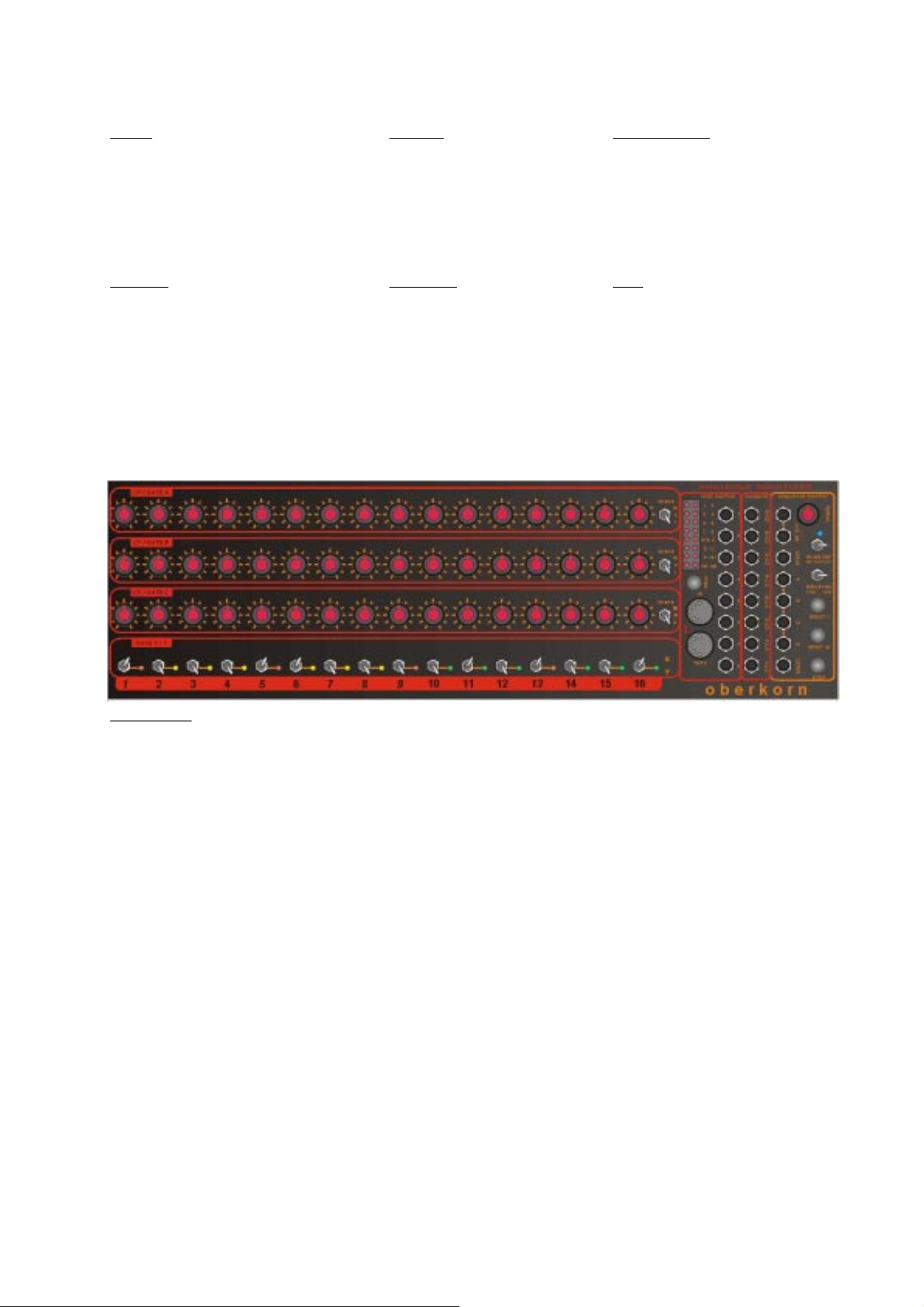
ANALOGUE SOLUTIONS
oberkorn
e&oe (c) 10-2001
8
Gate Channels A, B, C
Each row of CV pots CV-A, CV-B and CV-C, has a built in switch. Turn the switch fully anti-clockwise (you will feel
and hear a ‘click’) and the switch is off. Turn to the right (after the click) and the switch is on. The integral switches built
into the 3 rows of CV controls provide the Gate signals for channels GT-A, GT-B and GT-C.
As the Gate switch is built into the CV pot, we realise that this means that to have the step produce no gate output
means that the CV level will also be zero, but this was the only way to add a Gate channel in such a compact module
and also without adding to the cost. We could have left it out leaving nothing to complain about. But it does NOT add to
the price, so you are getting 3 extra Gate channels for free! So no complaints about the zero-CV with no-Gate situation.
If you do wish to use CV and Gate together controlling pitch and EG triggering, there are some ways around this
problem:
Add some Glide to the CV signal. In some situations this will hide/eliminate the side-effect.
Put the VCA control signal into ‘Gate’ not ‘EG’ amount mode (or have zero release time on the EG). So as soon as
the Gate goes to zero, the output of the synth patch will also be zero so you will not hear the pitch drop.
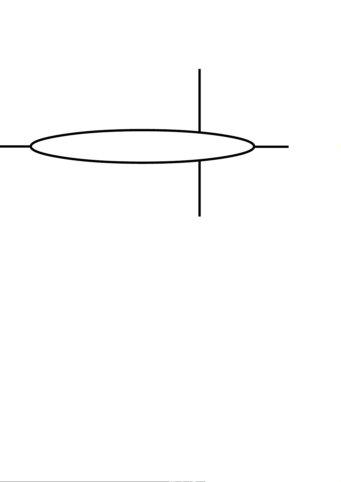
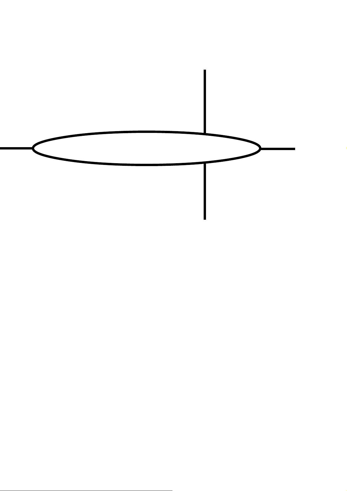
Additional Gate Channels - bottom row of toggle switches
GT-X When the switch is up, the Gate for channel GT-X is set for that step
GT-Y When the switch is down, the Gate for channel GT-Y is set for that step
Off When the switch is in the centre position, no Gate is set for either channel X or Y
CV and Gate Output Sockets
The resulting CVs and Gate patterns created from the CV/Gate channels are outputed via the CV/Gate sockets.
The CV sockets are labelled CV-A, CV-B and CV-C. These correspond to the appropriate row of CV pots. The CV
signals are normally used to control any control voltage input on a synth or modules, e.g. pitch, filter cut-off, VCA, etc.
The Gate sockets are labelled GT-A, GT-B, GT-C, GT-X and GT-Y. These correspond to the appropriate Gate
channels. The Gate signals are normally used to trigger envelope generators, or anything with a Gate/Trigger input
(drum machine/module, monosynth, another analogue sequencer, sample and hold, etc.).
The Gate output level is +7V. This can be changed to any value from 0 to 12V by changing some internal zener
diodes.
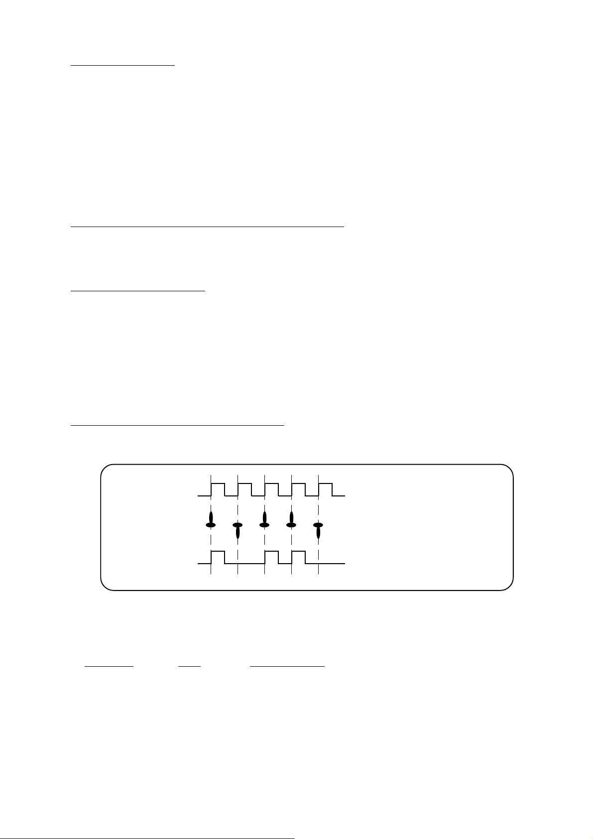
Gate Output Signals and Gate C Legato Mode
Normally, for each gate switch that is in an ‘on’ position, a gate signal is sent out of its gate socket. If 2 or more gate
switches in a row are all on, then the gate signal will go off briefly before going on again for the next consecative gate
signal. This way, for instance, an envelope will re-trigger. This is how gate channels X, Y, GT-A and GT-B work.
CLOCK
GATE SWITCH
UP=On
Gate output for channels
X, Y, GT-A and GT-B.
See how each gate switch
produces an individual gate
signal.
GATE OUT SIGNAL
The following section is for advanced users. It describes in more technical detail how gate channels X, Y, GT-A and
GT-B work. You only need to tackle this if you wish to fully exploit the direct MUX feature covered later in the manual.
The gate signal output is actually produced by ANDing (a boolean term) the state of the gate switch with the clock.
Gate Switch Clock Gate Signal output
off off off
on off off
off on off
on on on
From the above table, you can see a gate signal is only created when the gate switch is on and there is a clock
voltage present. As soon as the clock signal goes low (0v) or the gate switch is off, then there is no gate output.
figure 1