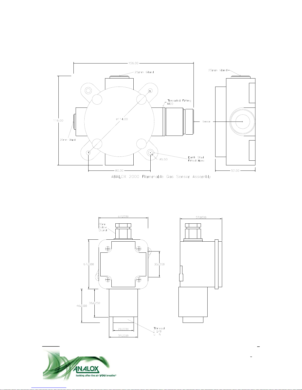
Analox 2000 – Flammable Gas Sensors – User Manual
Document Ref: SK0-810-04 January 2009
Page 6
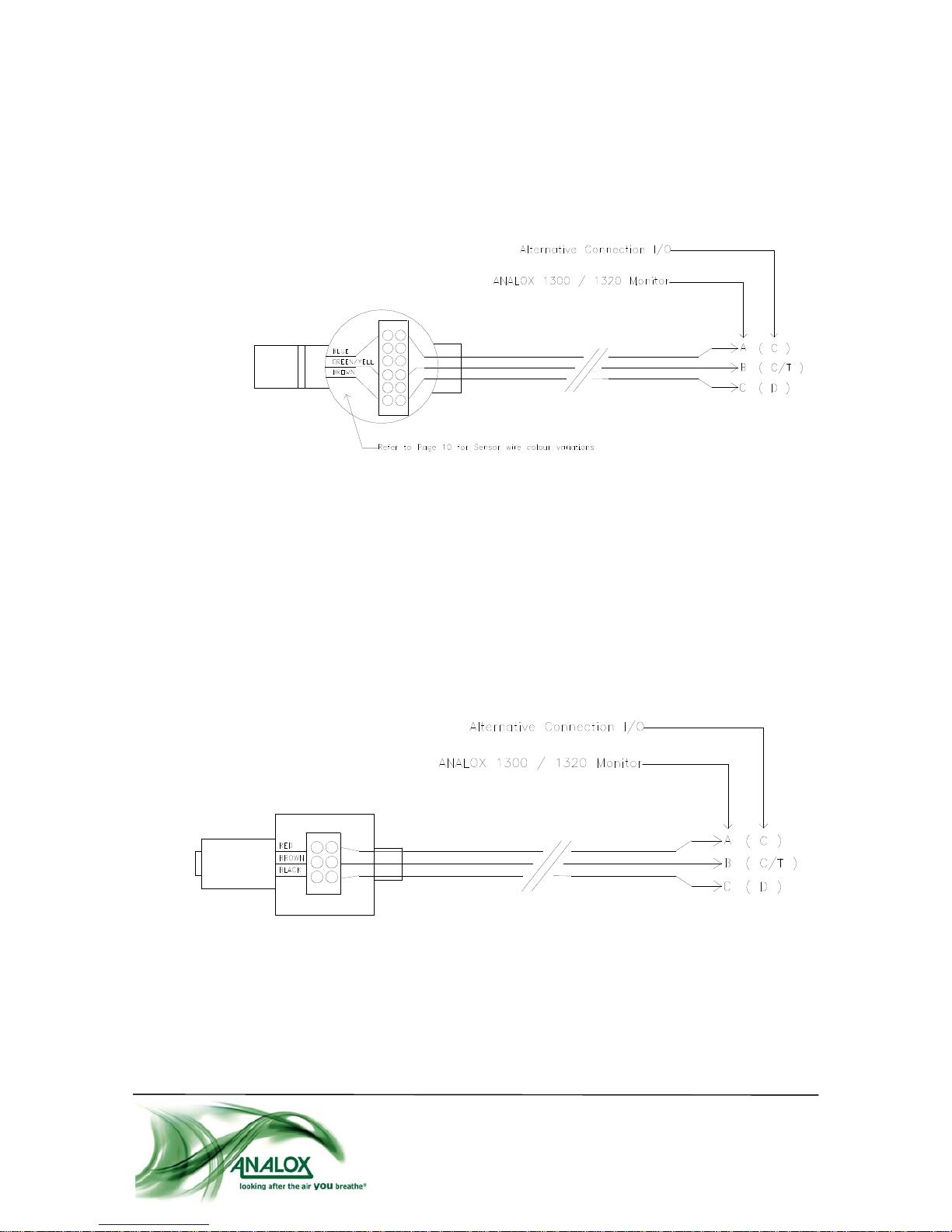
SENSOR SIGNAL CABLES
All the S.A.E.P. Flammable gas sensors require a Three Core cable between the sensor and
the measuring instrument. Because of the relatively heavy current demands of the Pellistor type
of sensors, the connecting cables must be chosen with care. Pellistors of the VQ21 type, which
are normally fitted in the Model 2000 and Model 2001, require an operating potential (at the
Sensor) of 2.00 volts DC at a current of 300 milliamps. When a current of this magnitude is
passed along signal cables, any significant resistance in the cables will result in a drop in
voltage along the cables. As an example : Assume a cable run of 100 metres is required
between the monitoring instrument and the sensor and the cross sectional area of the cable
chosen is 1.00mm2. Most manufacturers quote the resistance of this cable to be 19.1 Ohms
per kilometre, therefore in this case, a 100 metre length will have a resistance of 19.1 / 10 =
1.91 Ohms. Bearing in mind that as far as the loop current is concerned, the actual conductor
length is 200 metres, (100m to the sensor and 100m back again) the total cable resistance in
this case is 3.82 Ohms. Using Ohm's law to calculate the voltage drop across the entire cable:
Voltage Drop = Current x Resistance
Where Voltage is in Volts : Current is in Amps & Resistance is in Ohms
Voltage Drop = 0.3 x 3.82 = 1.15 Volts
This means that if the monitoring instrument supplies a drive voltage of 2.00 volts then the
sensor will only have 0.85 Volts applied to it. (2.00v-1.15v=0.85v). The pellistor sensor will NOT
operate correctly in this condition.
NOTE: Although the ANALOX 2000 & 2001 sensors use a 3 wire connecting cable, only two of
the wires carry the sensor excitation current. The third wire is connected to the centre tap of the
'Half Bridge' configuration. It only carries a signal voltage at very low current and may therefore
be ignored as far as resistance effects are concerned. Most monitoring instruments designed to
operate with Flammable gas detectors of the Pellistor type, have the facility for compensating,
within limits, for this voltage drop. The ANALOX range of monitors, 1300 and 1320, allow the
drive voltage to be adjusted up to about 3.8 volts. So, in the case of the above installation, the
1.15 volt drop across the cable could be compensated by adjusting the monitoring instrument
drive voltage to 3.15 volts. It is not necessary to carry out all of these calculations every time an
installation is done - correct operation of the sensor can be achieved by measuring the voltage
AT THE SENSOR JUNCTION BOX TERMINALS, as per the installation instructions in the
relevant monitoring instrument handbook. Data regarding maximum possible lengths for a
selection of commonly used cables with 3 different Pellistor sensors, is included in Appendix B,
at the end of this manual. A further point, which is often overlooked is that the resistance of
copper cable has a temperature co-efficient. The effect of this variation in resistance due to
temperature changes, can be significant on very long cable runs, particularly if the cable has a
small cross sectional area and is subject to large variations in temperature. The measuring
instrument is unable to distinguish between a change in cable resistance and a genuine gas
signal. Copper cable resistance is normally quoted at 20C and will vary by approximately
0.4% per degree C, as the temperature changes above and below this value. Using the above
cable installation as an example, the total loop resistance was calculated to be 3.82 Ohms at
20C. If the temperature of the cable drops to 0C then the resistance will change to 3.80
Ohms. At first sight, this may not seem significant but could result in drift of the ZERO reading
on the monitoring instrument.