Anaren AIR Module, Users Manual
3/18, 8/18/2010:3:57 PM
•Low Power Consumption
•Regulatory approvals for FCC
•Digital RSSI output
•Programmable channel filter bandwidth
•Programmable output power up to +10
dBm
•High sensitivity (–104 dBm at 1.2 kBaud,
1% packet error rate)
•Low current consumption (14.4 mA in RX,
1.2kBaud, input well above sensitivity
limit)
•Fast startup time: 240us from SLEEP to Rx
or Tx mode
•Separate 64 byte Rx and Tx FIFOs
•Data Rate: 1.2 – 500 Kbit/Sec
•Programmable data rate from 1.2 to 500
kBaud
•Sleep state: 0.4µA
•Idle State: 1.7mA
Canada under Industry Canada (IC) Radio
Standards Specification (RSS) RSS-210 and
RSS-Gen.
•No regulatory “Intentional radiator”
testing required to integrate module into
end product. Simple certification labeling
replaces testing.
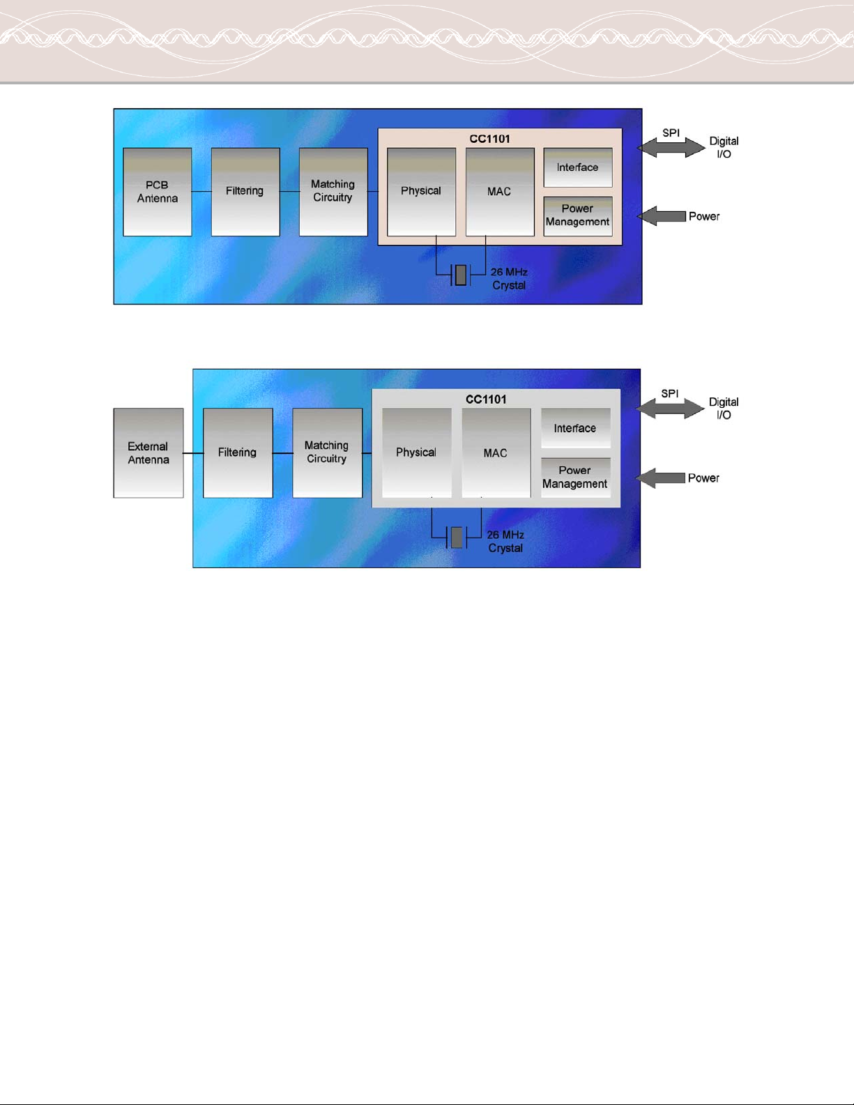
1.4. Theory of Operation
The A1101R09A and A1101R09C are for low power wireless applications in the US 902 – 928MHz ISM
band. The devices can be used to implement a variety of networks, including; point to point, point to
multipoint, peer to peer and mesh networks
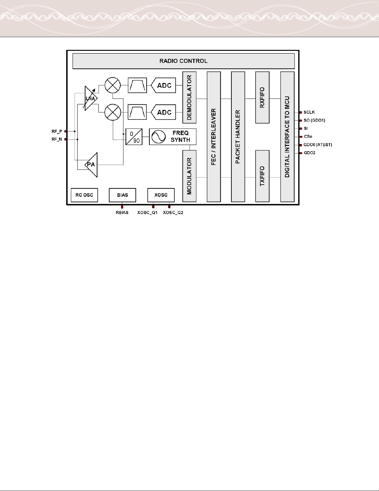
The A1101R09A and A1101R09C both interface to an application microcontroller via SPI bus. Physical
and MAC layer functionality are accessed via the SPI bus, through addressable registers as well as
execution commands. Data received or to be transmitted are also accessed through the SPI bus and are
implemented as a FIFO register (64 bytes each for Tx and Rx).
To transmit, a frame of data is placed in the FIFO, this may include a destination address. A transmit
command is given, which will transmit the data according to the initial setup of the registers. To receive
data a receive command is given, which will listen for a transmission and when one occurs put the
received frame in the FIFO. When neither transmit or receive is required the device can enter either an
Idle mode, from which it can quickly re-enter receive or transmit mode or it can enter a low power sleep
mode, from which a crystal startup is also required prior to transmit or receive operation.
Below a block diagram is given for each of the A1101R09A and A1101R09C modules.
•Antenna
oThe antenna couples energy between the air and the module. For applications where
installations are done by an end user (non-professional), an omni-directional antenna
pattern is desired, such that the application will work equally well in any direction.
Similarly for peer to peer or point to multipoint application an omni-directional pattern is
desired such that all nodes have a fair chance of communicating. The A1101R09A module
has an integral antenna that is near omni-directional, whereas the A1101R09C has
approved antenna options ranging from near omni-directional to shaped front/back
patterns (useful for inline, professional installations). Note that the end radiation pattern