Anchoring 1000 User manual


To begin with, we would like to congratulate you on your excellent choice of
windlass – we believe you will benefit from our product for many years to come!
We’re very proud that you chose Anchoring1000 Automatic Windlass. In order to get
the most out of it we recommend that you read through this manual once. Then save
it for future reference and to brush up on your acquired knowledge. This document
can be downloaded from our homepage www.anchoring.se.
You’re always welcome to contact us at Anchoring with your views and questions; reach us by
phone on: +46 (0)8 531 70 900, or fax us on: +46 (0)8 531 70 901. Our business address is:
ANCHORING AB
Box 20138
SE - 161 02 Bromma
SWEDEN
You can e-mail us through our homepage www.anchoring.se.
This Document…
The Manual consists of 6 chapters: the Introduction, Product Description, Assembly, Use, Tips &
Advice, ending with an In Depth-section. The Product Description gives you a complete listing of
the products we offer you moreover the windlass-package, such as Bruce-anchors and chock- and
anchor rollers, plus special features such as anchor davits. The chapter on Assembly guides you
through arranging the windlass-system onboard and calibrating the electronic settings necessary for
safe operation. In Use we give you a step-by-step instruction on how you operate with the steering
devices. Further on, we answer some FAQ’s in Tips & Advice and help you with troubleshooting.
Finally, as a bonus for the techno-buff, we go into detail in the ultimate part called In Depth.
Anchoring1000 Automatic Windlass
This automatic windlass was originally designed for the Swedish Defence Materiel Administration,
FMV. The Designer co-operated closely with FMV in the product development phase and worked
from technical requirements put forward by the Swedish Marine. This has resulted in a robust and
reliable construction with special functions added, such as reverse feed and overload auto-stop.
Rigorous testing was carried out by FMV within the collaboration.
The winch is also used in other professional situations where high demands on performance and
reliability is standard. The Swedish paper industry has discovered that our product is ideal for use in
their factories pulling the so called wire gauze, which is the cloth the paper-mass rests on when it’s
travelling through the wire rolls. The great force and precision that is needed in the papermaking
process requires a robust and dependable winching construction.
1

A Brief Introduction to the Product
The new, compact version of Anchoring’s Automatic Windlass simplifies the anchoring
manoeuvres for everyone onboard and is ideal for voyaging solo. You swiftly manage the whole
putting-in operation from the helm position by using the drum-release function. By using the remote
control system you may adjust your mooring from land by millimetre; stretch or release.
New Driving Gear
Placing the motor inside the winch drum ensures a compact design. Furthermore, our patented
mechanical ratchet has been integrated into the drum. The line distributor spreads the anchor line
evenly across the drum which prohibits the line from getting tangled. Thanks to the relatively large
diameter of the winch drum, the variation in pull from full to empty is insignificant which ensures
an even and reliable running action.
The new transmission achieves a very high outcome effect in relation to the motor input. This
guarantees great savings on energy and that the winch works significantly faster against great
resistance compared to competing products. Technically speaking, the Anchoring1000 has 90%
conversion efficiency compared to any competitor’s outcome of round about 50% efficiency.
Load-limiting and Auto-stop Functions
A new electronic feature, developed especially for the Swedish Defence material Administration,
FMV, has been added. It is a load-limiting device (extra function) which releases automatically for
the duration of overload and is then re-activated immediately. With the auto-stop function
(standard) the anchor stops first at the waterline during winching, and is then pulled with greatly
reduced power onto the anchor roller in the holdfast position.
Digital Comptometer
Control Panel 801 featuring a digital display (extra) enables you to verify from the bridge or cockpit
that the anchor is dropped properly – you’ll always know the amount of anchor line unwound. The
panel is delivered showing metric values in Europe and foot in the US. Also when the windlass is
winching, it’s useful to know when the anchor is coming up towards the boat. The panel features
ensure safer handling and a better overview – especially when there’s a risk for all of the anchor-
line to become unfurled. Please note that the catch that secures the line to the winch drum can take a
maximum load of 150 kg. This is a safety feature – a transverse stop at sea must be avoided at all
cost since it puts everyone onboard in grave danger of bodily harm – even at low speed.
The anchor line is made of wear-resistant polyester and has been primed with a water-stop. Its
ultimate tensile strength is 3 tons (= 3.000 kg) which means it’s stronger than an 8 mm steel cable
and considerably lighter. The surface area of the line offers a bolstering effect under water and a
springing action when anchoring and mooring.
2

Index
This Document… ................................................................................................................................1
Anchoring1000 Automatic Windlass..................................................................................................1
A Brief Introduction to the Product ...................................................................................................2
New Driving Gear ....................................................................................................................................... 2
Load-limiting and Auto-stop Functions .................................................................................................... 2
Digital Comptometer .................................................................................................................................. 2
Index ....................................................................................................................................................3
List of Products ...................................................................................................................................5
Delivery................................................................................................................................................6
Supplies ........................................................................................................................................................ 6
Anchor Davits.............................................................................................................................................. 6
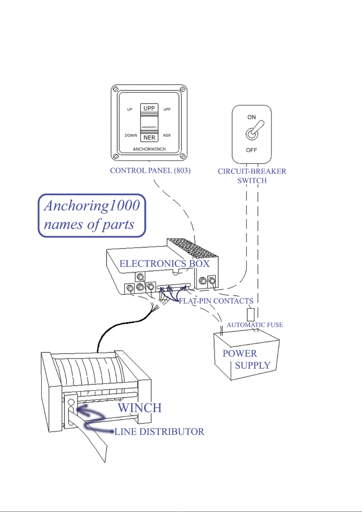
Designated Names...............................................................................................................................7
Important! ...........................................................................................................................................8
Power-supply Cabling................................................................................................................................. 8
Terminal Diagram...............................................................................................................................9
Winch and Chock Rollers......................................................................................................................... 10
Consider the B and M Dimensions .......................................................................................................... 11
Assembly Suggestions and Alternative Use......................................................................................12
Board Lead-through ................................................................................................................................. 13
Anchor Rollers........................................................................................................................................... 14
Anchor Davits............................................................................................................................................ 15
Fitting anchor davits 710 and 711 ........................................................................................................................... 15
Fastening and securing the anchor in holdfast position........................................................................................... 16
Casings ....................................................................................................................................................... 17
Recommendations for the Electrics and Placing of Electrical Components..................................18
Important!.................................................................................................................................................. 18
Setting the Auto-stop Function ................................................................................................................ 18
Please Observe!....................................................................................................................................................... 20
Electronic Settings for Anchor Davits 710 and 711................................................................................ 21
Control Panels ........................................................................................................................................... 22
Control Panels Connected in Series ........................................................................................................................ 22
Remote Control ......................................................................................................................................... 23
3

Important! .........................................................................................................................................24
Power Supply............................................................................................................................................. 24
User Instructions...............................................................................................................................25
General Description of Control Functions.............................................................................................. 25
Anchoring................................................................................................................................................................ 25
Winching................................................................................................................................................................. 25
Switches, Keys and Lights in Brief… ...................................................................................................... 26
Anchoring, Step by Step… ....................................................................................................................... 26
…with an Anchor Davit............................................................................................................................ 27
Other Steering Devices......................................................................................................................28
Remote Control (extra)............................................................................................................................. 28
Summer (extra).......................................................................................................................................... 28
Adjustments .......................................................................................................................................28
Maintenance......................................................................................................................................29
Remember to Save the EPROM! ............................................................................................................. 29
Safety during Assembly, Calibration and Maintenance..................................................................29
Calibrating................................................................................................................................................. 30
The Winch.................................................................................................................................................. 30
Line Length................................................................................................................................................ 30
Troubleshooting ................................................................................................................................30
Keep Us Informed .............................................................................................................................31
Technical Data ..................................................................................................................................32
4

Below all types of products we have on offer are listed. The standard windlass
package includes a winch and 60 m anchor line, cabling (excluding power-supply
cabling), an electronics box, a control panel 803 with switch-lever, the auto-stop
function, a separate circuit breaker and board lead-through (leading-in) material.
List of Products
Windlass package, 12V or 24V, includes: Product No. Pcs.
Winch 12V/24V 101/102 1
Electronics box (CPU etc.) plus motor cabling, 12V/24V 103/104 1
Control panel with switch-lever 803 1
Auto-stop function 805 1
Automatic fuse 806 1
Anchor line, 60 m. 709 1
Board lead-through material 712 1
All cabling (except from power-supply cables) is included, such as 10m modular cabling.
Accessories: Product No.
Anchor roller, simple 701
Anchor roller, hinged 702
Anchor roller, inset, simple 703
Anchor roller, inset, hinged 704
Chock roller, standard 705
Chock roller, extra tall 713
Casing for chock roller 705 706
Casing for winch 707
Anchor Davit > 10 kg 710
Anchor Davit < 10 kg > 20 kg 711
Bruce-anchor, 10 kg 750
Bruce-anchor, 15 kg 751
Mushroom anchor 12 kg 752
Mushroom anchor 16 kg 753
Shackle 708
Extra anchor line, 60 m. 709
Extra board lead-through material 712
Control panel with digital display 801
Remote control system incl. transmitter and receiver 802
Extra remote control (transmitter) 807
Summer 804
Reverse feed, 12V/24V, extra function 811/812
Load-limiting device, extra function 813
Lubrication kit 780
5

Delivery
With your windlass-delivery a packing list, a drilling pattern and, as apparent, this instruction
manual, are enclosed.
Please check that all parts are included according to the packing list. If this is not the case, we ask
you kindly to notify us within 8 days from receiving the delivery.
Supplies
In order to assemble and fit the windlass system, in addition to delivered Anchoring-material and a
set of standard tools, you will need:
- Fittings, i.e. screws in different sizes, nuts, washers etc. (see Chapter on Assembly)
- A drop of oil or grease for screw threads.
- Urethane-based sealing compound for outdoor use (e.g. Sikaflex-221 Technique), for sealing
and fastening the board lead-through.
- Cabling for connecting the power supply to the electronics box, as specified in the Assembly
chapter.
- A circuit-breaker switch for control current.
- Thin, strong line to stretch up between rollers during the preliminary assembly fitting.
Please Observe: Do use stainless fittings and electric cabling for marine use.
Furthermore, you will need an anchor roller, an anchor and, usually, a strategically placed chock
roller in order to achieve a centred anchor-line direction. You can order all of these from us if you
don’t have them already.
In some cases material for reinforcing the hull as well as other bond positioning and lead-through
solutions are needed.
Anchor Davits
We offer two types of anchor davits to be mounted onto negative/inverted transom sterns and in
other instances where a simple anchor roller doesn’t suffice. The launching arm on davit 711 is
120 mm longer than on 710 – all else is the same. The torsional forces affecting an anchor davit are
substantial and the stern usually needs reinforcement – more on that in the Assembly and Use
chapters.
6

Designated Names
A schematic plan of the main parts of our automatic windlass - what they’re called throughout this
instruction and, schematically, how they relate to each other.
7

Plan out your assembly carefully before you start mounting the windlass. Then make
a provisional fitting to control angles and distances. Please attempt to fit the anchor
line so that it is out of the way when you move onboard, if possible, and make sure to
mount appropriate protection (e.g. plastic tubing) where necessary. Preferably, fit
Anchoring1000-casings onto the winch and rollers, or other protective devices that
prevent personal injury.
Important!
- The winch must be placed so that it is never flooded or submerged in water.
- The electronics box must be placed inboards, in a dry and not too hot environment.
- Control current to the electronics box must be taken directly from the power-supply poles to
avoid currency disturbance. The flat-pin contacts called K (-) and L (+) are connecting ports
for the control-current cabling on the new box-design.
- Do not carry out assembly work while the system is alive – connect the power-supply cable
to the positive element last.
- The anchor line must run without restraint and in a centred position on the rolls.
- The recommended distances between winch and rolls, as specified in this instruction, must
be adhered to.
Seven generic recommendations for the preliminary assembly:
- Place the winch so that the drum axis is level.
- Centre the anchor line relative to the winch and on chocks and anchor roller.
- Make sure the line runs through the centre of the line-distributor gap in and out of the winch.
The line must not be pulled against the corners of the gap since the calibration gauge, sown
into the line, can get damaged and the line chafes from the friction.
- Use sturdy positions for fastenings.
- Protect all current-carrying equipment against water.
- Make all necessary calibrations before testing.
- Please observe that the mooring manoeuvre cannot be simulated on land since air and water
have different viscosities. The anchor falling through air at a high speed may result in
reverse rolling of the drum and severely tangled anchor line.
Power-supply Cabling
When you’ve measured the distance between
the power supply and the electronics box, you
should get power-supply cabling (black -, and
red +) of the correct end-face measure and
length as listed to the right.
Cabling connecting the
power-supply to the electronics box
Distance = length End face
0-2 m 16 mm2
2-4 m 25 mm2
4-5 m 35 mm2
5-8 m 50 mm2
8-10 m 70 mm2
10-12 m 100 mm2
8

Terminal Diagram
9

Select Strong Fastening Positions
Always make sure the bonding area is strong enough to support the winch, chocks and anchor
rollers where you want them positioned. Measure up the connecting points with the relevant stress
and strain the component will suffer in mind. Please observe that the anchor is pulled into its
holdfast position by force of about 100 kg (800-1000 Newton), upon which the winch action is
automatically stopped. In extreme situations, the winch may pull with a force of up to 1 metric ton
during this moment – this is in case the low-energy phase hasn’t been set properly on a rotary
switch, as explained on page 18-20. Also consider that the anchor line’s rupture limit is up to
3 metric tons.
The load is normally distributed onto four M8-screws per winch, chock and anchor roller. The
greatest stress caused by the line-pull will probably be exercised on a chock roller since the load
increases with the refracting angle.
Always use large washers so that the stress is absorbed by larger areas in materials that are weaker
than steel. Don’t forget to use sealant around external screw holes. Mount the board lead-through
from the outside because the anchor-end is moving up and down more when pulled in.
Winch and Chock Rollers
The winch measures 330 x 397 x 210 mm.
The winch can be placed anywhere on the boat, except where it is exposed to being flooded or can
end up under water. In many types of boats it is suitable to build a platform for fitting the winch
onto, especially when it is placed inboard against the hull or in the keelson.
Place the winch-drum axis horizontally and centre the anchor line from the winch via chocks and
anchor roller as much as you can.
Make sure the anchor line travels through the centre of the line-distributor gap to and from the
winch drum. The line must not be pulled hard against the upper or lower corners of the gap since
the calibration gauge, sown into the line, can be damaged and the line gets chafed.
Use the following measurements as a guide when adjusting the line height:
- Chock roller 705 has a line height of 65 mm.
- Chock roller 713 is adjustable and has two line-height positions, 120 and 140 mm.
Chock rollers 705 and 713 can be used in different combinations, but the Anchoring 706-casing
only fits over chock 705, i.e. the lower one. The screw holes for mounting have a diameter of 9 mm,
and fits M8-screws. The screw-hole spacing on the chocks is 110 x 83 mm.
10

Consider the B and M Dimensions
When you position the winch in relation to the rolls, you must keep to these measurement
recommendations. Dimension B between the anchor and the nearest roll (illustrated below) should
be 250 mm or more, the absolute minimum space being 150 mm. This is to allow the anchor end to
move upwards when released.
The aim is for dimension M to be as long as possible in order to alleviate the strain on the line
distributor. If you’d rather measure the space between the line distributor and the nearest roll,
deduct 310 mm from the suitable M-value in the table below.
The minimum M-dimension is depending on the
weight of your boat. If the boat weighs up to
3 tons the space should be at least 600 mm.
Dimensions for heavier vessels are shown in the
table to the right.
Boat’s weight, tons M-minimum, mm
3 600
5 650
8 750
11 850
15 950
20 1050
25 1150
30 1250
11

Assembly Suggestions and Alternative Use
We recommend that you place
both the winch and the
electronics box inboard, since
they must be protected from
flooding and breakers.
If the winch is placed outboard
on deck it should be covered
by casing.
Inboard placement with an
anchor roller on deck.
Inboard stern placement with a
chock by the lead-through.
Inboard stern placement with
an anchor roller on the landing.
Anchor davit for slanted and
negative transom stern.
Outboard stern placement with
a hinged anchor roller.
Inboard placement with the
holdfast through the hull.
Inboard placement with the
winch hanging under deck.
Outboard placement with the
winch on deck.
The pulling power of the
windlass can also be used for
winching the boat onto a trailer
or when taking the boat up.
The anchor line can function as
a holding rope attached to a
buoy.
12

Board Lead-through
When the winch is placed inboard you will need to make a hole through the hull. The anchor line
should travel through the centre of the lead-through without touching the sides, in order for the
winching to work most favourably and to avoid fraying the line. Consequently, the board lead-
through should be placed directly in line with the anchor-line route – a chock roller placed in
connection to the lead-through is often necessary to assure this. The drill hole for fitting the lead-
through should have a diameter of 60-62 mm. Start by drilling small holes on the position you’ve
decided on and try out the line direction with a thin, strong piece of string to find the centre.
Fit the board lead-through piece from the outside so that the larger rounded edge sits outboards –
this is because the line movements are greater outside the lead-through piece. Fix the piece with a
urethane based compound for outdoors use, e.g. Sikaflex-221.
Keep in mind that some water always travels up with the line during winching. The line can be
fitted with a casing such as a piece of plastic tubing to protect inboard furnishings from stains.
13

Anchor Rollers
Place the holdfast anchor roller at a position where anchor line and anchor travels freely.
Aim to place the holdfast far away from the hull so that the anchor can oscillate without crashing
into the boat when being winched. The edge of the holdfast’s bottom plate should be positioned
level with the edge of the boat or the landing – never inside of the rim (except for recessed anchor
rollers).
Fasten the anchor roller with a minimum of four M8-screws. The screw holes are 9 mm in diameter.
Aim for the widest possible distance between the fastening screws in order to distribute the strain on
the surface and to keep the holdfast in a tight position when the anchor is being pulled to the sides
during hoisting.
The simple anchor rollers (701/703) are normally used when the angle of the anchor line coming
into the roll from a chock or the winch is less than till 50 degrees in relation to the plumb line. At
greater angles the hinged anchor rollers (702/704) are more suited to allow the anchor to drop by its
own weight when releasing the clutch.
14

Anchor Davits
The anchor davit is most commonly used on sailing boats with inverted or integrated transom
sterns, where a regular holdfast roll would be inadequate. A davit consists of the davit-housing
containing a spring and a spring plate, a launch arm and an anchor roller, product no. 702.
Furthermore, we include an anchor support which holds the anchor in a backward-leaning position.
Rope and fittings are not included. All metal is stainless. The anchor support is made from white
POM plastic (acetaldehyde) and the rolls from black POM on a steel axis. The model is designed
for Bruce-anchors, but may work with other types of anchors.
Fitting anchor davits 710 and 711
All boats are unique in design and we can only give the following generic recommendations:
Maximize Y and minimize V (see below) when you fix the davit to its foundation. The launch arm
on davit 711 is 120 mm longer than on 710, and the measurement indications below list dimensions
for type 711 (with 710-dimensions within parenthesis).
You will need fittings, tools and reinforcement materiel for the transom stern in most cases. For
fastening the davit-housing ten M8-screws plus washers and nuts are needed. Two of the screws,
those in position aillustrated above, should have low heads. The three screws holding the spring
should be circa 7 mm longer than the other. For the anchor support two M8-screws with washers are
needed. (30 mm thread in material).
The davit housing must be positioned so that the anchor travels freely in both directions (see U
above, and f below, next page). The M8-screw should close with the foundation and be fastened so
that the housing can support horizontal pull without moving.
The torsional forces from a davit are substantial and normally the transom stern will need to be
reinforced to support the construction, as mentioned before. The strain on the boat, fittings and axis
are the greatest:
- when the anchor has stuck. Gives aa pull, pressure in e, a leverage effect by U.
- when the launching arm is rising. Gives horizontal pull in all the fittings (Maximize Y).
- by crosswind. Gives pull in all fittings as well as pressure alongside the housing, and a
leverage effect by V and Z, round fitting e.
15

The spring can be placed in three alternative position; b-c, c-d, d-e, (see below) and is fastened
under the spring plate with the same screws that hold the davit housing. Position c-d is standard,
position b-c lifts the arm and d-e lowers it. To minimize V, avoid placing the spring between b-c,
rather use d-e. Thread and twist the spring so that it closes with the screw under the plate and the
screw heads above it; respectively turn the screw heads so that the spring fits and closes against
them.
Fastening and securing the anchor in holdfast position
All davit arrangements demand some manipulation by use; namely to soften the fall when the
launching arm is turned by holding on to the anchor holding-rope, to turn the anchor plus bracing
the holdfast roll mot against crosswind.
The parking method is depending and the angle of the transom stern and the anchor’s pivotal point:
- If the anchor-stock falls against the arm easily, you connect the anchor rope to the holdfast
loop and fasten the other end to the boat.
- If the anchor falls more easily out into the water, you secure the rope to the anchor itself.
The anchor rope then follows the anchor to the bottom and will have to be collected with a
boat hook when the anchor’s to be turned during hoisting.
Turn position Normal holdfast position Backward-leaning position
16

Casings
The external measurements for the winch casing are 425 x 380 x 230 mm.
The casing is fastened, covering the winch, with two screws holding it in position (see below). Take
off the side plates on the winch to get to thread the screws. The screws are fastened to the flange
with adjustment nuts – do grease the thread if possible. Don’t forget to fit the side plates onto the
winch before you fit the casing permanently.
Regarding casing 706 for the chock roller 705; place the angle irons on top of the chock roller’s
foot-plates and fix with the chock’s fittings. Direct the screws straight at the angle irons. Grease up
the thread and make sure the screws turn easily.
17

Recommendations for the Electrics and Placing of Electrical
Components
The following instructs you on calibrations that must be made during assembly. Look
up the terminal diagram for reference on page 9 in this chapter. But first of all; some
good advice on handling electrical components.
Important!
- Protect all live equipment against water.
- The electronics box should be placed inboard, in a dry spot that is not too hot.
- Control current to the electronics box must be taken directly from the power supply with
separate cabling to avoid interference problems.
- Cabling to the control panelling and control current should be away from other cables
carrying high voltage.
- Do not carry out work on a live system - connect the positive lead last.
- Calibrate all settings before you make a test run.
Make sure you place electrical components and contact surfaces inboard as far as possible, in a dry
and not too hot environment. Especially the CPU-card and modular contacts are sensitive to damp.
All cable sockets on the power supply and the electronics box should be protected by grease against
oxidation. The perforated part of the box should be placed at least 50 mm from inflammables.
Electrical cabling is fitted according to the diagram on page 9. The windlass should run on batteries
that hold sufficient capacity. The winch is secured for 63A. Current can be substantially stronger
under stress. Do connect an extra battery if the cable is long. The voltage should not go under 10V.
Bear in mind to have the automatic fuse, which is triggered for instance when the anchor has stuck,
readily available.
Always cut the current before you make adjustments to the windlass and its moveable parts. Never
connect electrical components or adjust calibrations on a live system. Always hold on to the cable
socket, never the cable itself, when you disconnect.
Setting the Auto-stop Function
You will only need to set up parameters for the Rinsing position!
18

From the rinsing position the winch will haul the anchor with greatly reduced speed and power and
pull it into holdfast against the anchor roller. The motor current is automatically broken when the
set power limit is reached = pre-set during manufacturing to circa 1000 N, i.e. 80 - 100 kg.
You set this position by turning the rotary switch BCD1 on the CPU-card in the electronics box.
The rotary switches are the two yellow discs found at the top right-hand corner of the CPU-card,
and BCD1 is the one to the right.
If the other rotary switch isn’t leaded, make sure it is pre-set to F.
Turn off the control current before you make adjustments to BCD1. This switch has precise
positions and functions as a memory for the rinsing position. The processor (i.e. CPU) takes the set
value anew each time the power is switched on and the system is activated.
The rotary switch is marked with a scale 0-9, A-F. Turn the disc to the desired position with a small
screw driver. There are only 16 positions which snap-fits when you turn.
The correct setting is derived from measuring the distance, C, between the anchor-end and the
winch’s line distributor according to the illustration below, next page. Then use that measure to read
the correct position from the table to the left.
If the measure C is greater than 4.8m, you should contact Anchoring for instructions.
19
Table of contents
Popular Boating Equipment manuals by other brands

Vetus
Vetus BOW16024C Operation manual and installation instructions

Plastimo
Plastimo PWH 500 Installation, operation & maintenance instructions

DAVIS
DAVIS Mark 3 manual

NUCANOE
NUCANOE 2525 Assembly & installation

Harken
Harken Carbo Ratchamatic Series Online instructions

Floe
Floe SHOREWAY QUICK PIVOT Assembly instructions

PRIJON
PRIJON PRO-seat-system How to Adjust

Shoremaster
Shoremaster Bow Guide 7k Vertical instructions

EZ Dock
EZ Dock 204010 installation instructions

Raritan
Raritan RUDDERMASTER Installation and maintenance instructions

Ultraflex
Ultraflex UFLEX ZTF Tiller System KIT QU1 installation manual

Hunter
Hunter 27 BIMINI installation instructions