manuals.online logo
Brands
  1. Home
  2. •
  3. Brands
  4. •
  5. Floe
  6. •
  7. Boating Equipment
  8. •
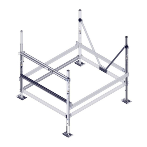
  9. Floe VSD 6000 User manual

Floe VSD 6000 User manual

Other manuals for VSD 6000

4

Other Floe Boating Equipment manuals

Floe PONTOON CRADLE PADS User manual

Floe

Floe PONTOON CRADLE PADS User manual

Floe X-SHALLOW 510-17100-00 Quick start guide

Floe

Floe X-SHALLOW 510-17100-00 Quick start guide

Floe V1600 PWC User manual

Floe

Floe V1600 PWC User manual

Floe V2602 LENGTH BUNKS User manual

Floe

Floe V2602 LENGTH BUNKS User manual

Floe 510-20000-00 User manual

Floe

Floe 510-20000-00 User manual

Floe VSD6500 User manual

Floe

Floe VSD6500 User manual

Floe 510-17700-00 User manual

Floe

Floe 510-17700-00 User manual

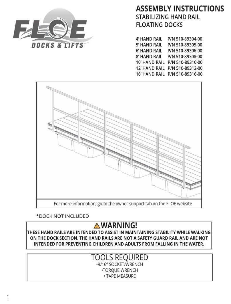
Floe 510-89304-00 User manual

Floe

Floe 510-89304-00 User manual

Floe V-2000 User manual

Floe

Floe V-2000 User manual

Floe VSD 3800 User manual

Floe

Floe VSD 3800 User manual

Floe VSD 6000 User manual

Floe

Floe VSD 6000 User manual

Floe MAXIS User manual

Floe

Floe MAXIS User manual

Floe V-2000 User manual

Floe

Floe V-2000 User manual

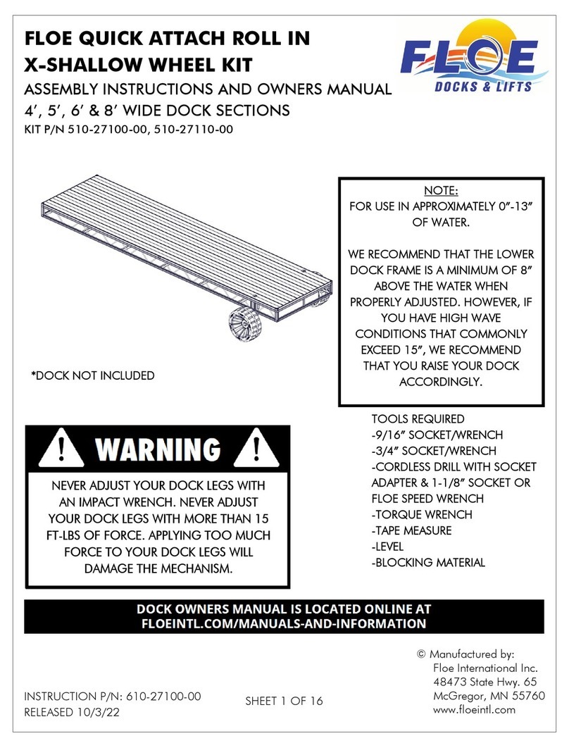
Floe 510-27100-00 Quick start guide

Floe

Floe 510-27100-00 Quick start guide

Floe VSD 6000 User manual

Floe

Floe VSD 6000 User manual

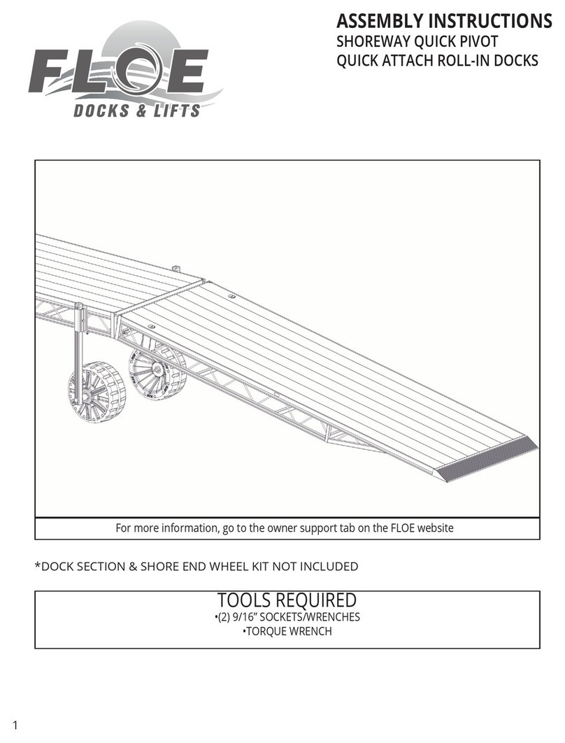
Floe SHOREWAY QUICK PIVOT User manual

Floe

Floe SHOREWAY QUICK PIVOT User manual

Floe VSD 8000 User manual

Floe

Floe VSD 8000 User manual

Floe V1600 PWC User manual

Floe

Floe V1600 PWC User manual

Floe 510-27500-00 Quick start guide

Floe

Floe 510-27500-00 Quick start guide

Floe 510-27400-00 Quick start guide

Floe

Floe 510-27400-00 Quick start guide

Floe VSD 5000 User manual

Floe

Floe VSD 5000 User manual

Floe VSD 6-8000 User manual

Floe

Floe VSD 6-8000 User manual

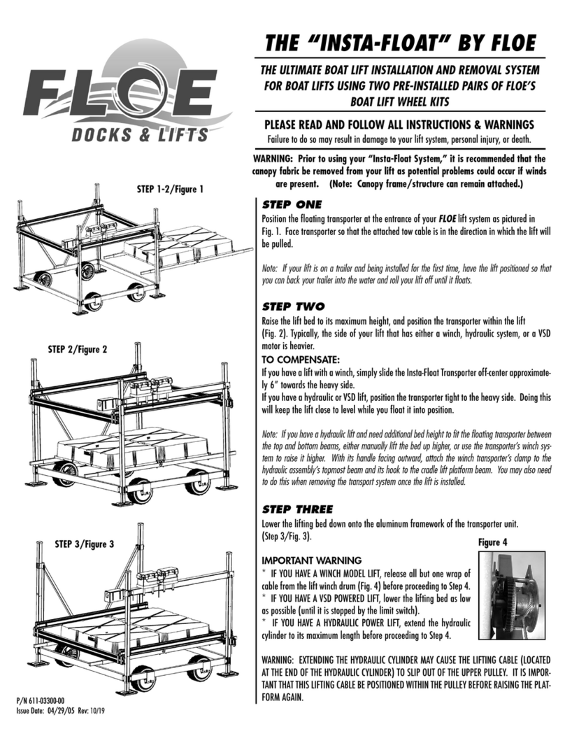
Floe INSTA-FLOAT Product manual

Floe

Floe INSTA-FLOAT Product manual

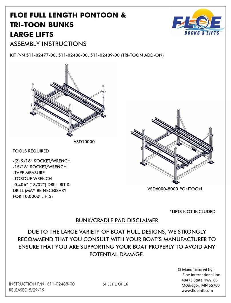
Floe FULL LENGTH BUNKS User manual

Floe

Floe FULL LENGTH BUNKS User manual

Popular Boating Equipment manuals by other brands

SureShade RTX Installation instructions manual

SureShade

SureShade RTX Installation instructions manual

Ideal Windlass CWM Installation, operation & maintenance instructions

Ideal Windlass

Ideal Windlass CWM Installation, operation & maintenance instructions

Access BIMINI Assembly instructions

Access

Access BIMINI Assembly instructions

Exalto 240BS manual

Exalto

Exalto 240BS manual

Faun C40 Trackway user manual

Faun

Faun C40 Trackway user manual

Humphree HCS-5 installation manual

Humphree

Humphree HCS-5 installation manual

Vetus BOW4512D Operation manual and installation instructions

Vetus

Vetus BOW4512D Operation manual and installation instructions

Dock Doctors SLIDING BOARDING STEP Assembly instructions

Dock Doctors

Dock Doctors SLIDING BOARDING STEP Assembly instructions

Mastervolt Mass Combi 12/2000-100 Quick installation

Mastervolt

Mastervolt Mass Combi 12/2000-100 Quick installation

SeaView PM5-FMD-8 installation instructions

SeaView

SeaView PM5-FMD-8 installation instructions

Hobie Mirage 360 manual

Hobie

Hobie Mirage 360 manual

Zattini Group bamar BOXTRON E14S Use and maintenance instruction manual

Zattini Group

Zattini Group bamar BOXTRON E14S Use and maintenance instruction manual

Hobie Getaway Hatch instructions

Hobie

Hobie Getaway Hatch instructions

NUCANOE 3005 Assembly instructions

NUCANOE

NUCANOE 3005 Assembly instructions

Westland T-Top Console Cover installation manual

Westland

Westland T-Top Console Cover installation manual

Furuno TZTL12F installation manual

Furuno

Furuno TZTL12F installation manual

ShoreLand'r DUB 2314 install guide

ShoreLand'r

ShoreLand'r DUB 2314 install guide

Wichard Gyb'Eas manual

Wichard

Wichard Gyb'Eas manual

manuals.online logo
manuals.online logoBrands
  • About & Mission
  • Contact us
  • Privacy Policy
  • Terms and Conditions

Copyright 2025 Manuals.Online. All Rights Reserved.

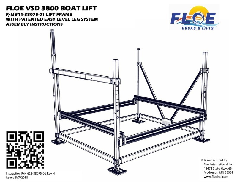
Floe VSD 6000 Boat Lift
P/N 511-60055-01 Lift Frame
With Easy Level Legs (Patent Pending)
Assembly Instructions
Manufactured by:
Floe International Inc.
48473 State Hwy. 65
McGregor MN.
www.floeintl.com
UPDATED: 4-04-05
P/N 611-60055-01
SHEET1 OF12
TOOLSREQUIRED
(2) 9/16" SOCKETSOR
WRENCHES
(2) 3/4"SOCKETSOR
WRENCHES
FRAMING SQUARE
TORQUEWRENCH
LOCKING PLIERS
VSD-6000 FRAME EXPLODED VIEW
101
102
103
SUB-ASSEMBLIES
104
105
106
107
108
109
SAND PAD111-00140-0027 4
4
4
4
1
4
2
1
2
4
4
4
4
1
8
4
4
4
8
1
8
2
1
2
4
1
1
4
1
1
2
4
111-00199-0049 001-47532-00
001-70118-00
001-70211-00
001-23876-00
001-70125-00
001-70110-00
001-33018-00
111-00200-00
003-40001-00
54
57
58
55
56
51
53
52
50
38 007-05023-00
007-09155-00
007-09150-00
007-07704-00
007-07705-00
007-05079-00
007-05024-00
111-00198-00
007-09161-00
007-07625-00
011-15000-00
43
46
47
48
45
44
41
42
39
40
006-11002-00
006-10202-00
911-08501-00
911-10301-00
111-00197-00
006-10207-00
007-05010-00
007-05500-00
006-15500-00
007-05013-00
33
35
36
37
34
30
32
31
28
29
6" SHEAVE W/BUSHING
1"-5 ACME THREADED ROD - 41"
HHCS, 3/8-16 x 3 3/4" ss 18-8
HHCS, 1/2-13 x 2" ss 18-8
HHCS, 3/8-16 x 6" ss 18-8
SHCS, 1/2-20 x 1 1/4" BLACK
HHCS, 3/8-16 x 1 3/4" ss 18-8
3/4" USS FLAT WASHER ZINC
RUBBER BUSHING
7 1/4" SHEAVE ASSY
SHEET 2 OF 12
4.5" CORNER POST CAP
SPACER TUBE - FRONT CRADLE
SPACER TUBE - SIDE CRADLE
TOP BEVEL GEAR - 1:1
UHMW WEAR PAD- 1/4" x 1/2" x 6 1/2" LG.
CRADLE GUIDE WEAR PAD
CRADLE U-CLAMP 2.875"
REAR CRADLE BEAM 127"
FRONT LEVELING CABLE - 213 3/8"
SIDE LEVELING CABLE - 190 1/2"
INNER SCREW LEG WELDMENT
BOTTOM BEVEL GEAR - 1:1
BEVEL GEAR ADJUSTMENT SCREW
SIDE CRADLE SHEAVE SPACER
1 1/8" THRUST BEARING
BALL SCREW END STOP PLATE
LIFTING CABLE 237"
65" BALL SCREW 40-10mm w/NUT
4" CLAMP SHEAVE
7" LIFTING SHEAVE
1" SHEAVE PIN
QTY.
1
2
4
2
1
2
1
3
2
4
2
1
1
1
1
1
1
1
2
1
1
1
1
1
7
1
6 002-04226-00
002-04207-0017
002-04352-00
002-04245-00
002-04354-00
002-04353-00
111-00239-01
002-04230-00
002-04224-00
002-04223-01
002-04241-00
22
25
26
24
23
19
20
21
18
002-04208-00
002-04209-00
002-04210-00
002-04211-00
002-04212-00
002-04357-00
002-04356-00
002-04216-00
002-04217-00
002-04215-00
11
14
15
16
12
13
9
10
7
8
PART NO.
002-04351-00
002-04202-00
002-04205-00
002-04355-00
002-04204-001
4
3
5
2
NO.
CRADLE GUIDE
UPPER CLAMP (UNIVERSAL)
UPPER CLAMP (FRONT)
UPPER CLAMP (REAR)
BALL SCREW TUBE - 109"
CORNER POST 89.5" LIFTING (.125)
LEVEL LEG BRACKET
FRAME BEAM LIFTING CLAMP
FRAME BEAM CLAMP (OUTER)
FRAME BEAM CLAMP (RF LR)
SIDE CRADLE (RIGHT) 126.5"
SIDE CRADLE (LEFT) 126.5"
V-BRACE CLAMP (MALE)
V-BRACE CLAMP (FEMALE)
FRONT CRADLE BEAM 127" (.188)
CORNER POST 89.5" (.125)
CORNER POST 89.5" MOTOR (.125)
4.5" PULLEY CLAMP (INNER)
4.5" PULLEY CLAMP (OUTER)
4.5" BALL SCREW CLAMP
CABLE HOLDER
6" SIDE FRAME BEAM 108"
8"F/R FRAME BEAM 118"
CRADLE LIFT CLAMP 3.875"
DESCRIPTION
V-BRACE 79.313"
CRADLE CLAMP 1.75"
1
1LIFTING CABLE PULLEY CLEVIS
2" CLEAVIS SHEAVE
86
87 007-05068-00
007-07626-00 HHCS, 3/4-16 x 2" ss 18-8
INCLUDES ITEMS 12,44,46,57,65,69,85
7500/6000# INNER SCREW LEG ASSEMBLY
INCLUDES ITEMS 6,10,31,32,33,43,45,49,66,69
INCLUDES ITEMS 6,11,31,32,33,43,45,49,66,69
INCLUDES ITEMS 16,17,18,20,25,26,34,35,41,42,68,70,77,79,94
INCLUDES ITEMS 15,21,24,34,36,55,56,59,79,108
INCLUDES ITEMS 5,7,8,15,16,22,34,54,55,79,108
INCLUDES ITEMS 5,7,9,15,22,34,54,55,59,79,108
INCLUDES ITEMS 19,28,38,39,40,72,75,76,90
6000# BALL SCREW TUBE ASSEMBLY
INCLUDES ITEMS 23,36,37,47,48,51,52,62,67,72,80,81,84,91,92,93,95,96,97
V6000 CORNER POST ASSY (LR)
111-00136-00
111-00190-01
111-00187-00
V6000 SIDE CRADLE ASSEMBLY (RIGHT)
V6000 SIDE CRADLE ASSEMBLY (LEFT)
V6000 FRONT CRADLE ASSEMBLY (.188)
V6000 CORNER POST ASSY (RF)
V6000 CORNER POST ASSY (RR)
V6000 CORNER POST ASSY (LF)
111-00246-00
111-00184-00
111-00185-01
111-00186-00
001-70394-00
111-00188-00
111-00189-00
88 1
FRONT CRADLE SHEAVE SPACER
FRAME BEAM CLAMP (LF RR)
6" FRAME BEAM SPACER
8" FRAME BEAM SPACER
HHCS, 1/2-13 x 5" ss 18-8
HHCS, 1/2-13 x 4" ss 18-8
NUT, JAM 3/4-10 ss 18-8
1/2" FLAT WASHER USS ss 18-8
NUT, 3/8-16 ALUMINUM NYLOCK
3/16" x 7/8" DOWEL PIN
NUT, 1"-5 ACME - BRASS
5/32" x 15/16" GROOVE PIN
3/16" x 1 3/4" ss SPRING PIN
CARRIAGE BOLT, 5/16-18 x 5" ss 18-8
1/2" FLAT WASHER SAE ss 18-8
NUT, 5/16-18 ALUMINUM NYLOCK
HHCS, 3/4-10 x 2 1/2" ss 18-8
NUT, 1/2-13 ALUMINUM NYLOCK
HHCS, 3/4-10 x 3" ss 18-8
SHCS, 3/4"-16 X 1 3/4"
HHCS, 1/2-13 x 3" ss 18-8
3/8" SAE FLAT WASHER
BALL SCREW NUT BLOCK - UHMW
NUT, SLOTTED 1 1/8-12
NUT, 1/4-20 ALUMINUM NYLOCK
CARRIAGE BOLT, 1/4-20 x 2" ss 18-8
65 001-70365-00 3
76 001-26911-00
006-10208-00
001-76071-00
001-75123-00
001-74404-00
001-76072-00
007-05000-00
007-05063-00
001-75001-00
001-74423-00
81
85
82
84
83
79
78
77
80
001-70817-00
001-71022-00
001-74165-00
001-70363-00
001-70861-00
001-71021-00
001-70819-00
001-23933-00
001-71017-00
001-26969-00
71
73
74
72
75
66
68
67
70
69
4
1
1
4
1
1
17
32
4
8
NUT, JAM 1"-8 ss 18-8
8
32
4
4
24
2
7
8
4
1
QTY.
002-04227-00
911-10501-00
911-10601-00
001-70223-00
001-70219-00
PART NO.
001-70215-00
60
63
62
61
64
NO.
59
DESCRIPTION
14
4
4
6
3
2
120 VAC VSD DRIVE TRAIN89 1
007-05224-0091 1" ID RIGID COUPLER1
1/4" SQ. x 3" KEY
BEARING BLOCK
007-05222-00
002-04238-00
93
92 1
1
1/2" FLAT WASHER - BRASS001-75210-0090 8
196 007-05126-00 M8 x 1 GREASE ZERK (FLUSH)
6000# LIMIT SWITCH ASS'Y111-00213-0197 1
HHCS, 1/2-13 x 3/4" ss 18-8
HHCS, 3/8-16 x 4 1/2" ss 18-8
001-70203-00
001-70121-00
95
94 2
1
511-75003-00
511-75005-00 1 24 VDC VSD DRIVE TRAIN
DRIVE TYPE OPTION
HHCS, 1/2-13 X 2 1/4" 18-8 ss001-70212-0098 4
VSD-6000 FRAME EXPLODED VIEW
21
24
4
2
31
15
15
16
6
6
7
78
9
10 11
12
79
14
28
29
27
31
33
44
45
46
45
49
49
55
79
54
79
80
61 41 18
58 80
61 73 80
7360 80
7361 80
7360 80
60 6173
66
69
69
69
66
103
101 102
105
104 20
10722
22 106
98 80
98
80
8098
43
32
65
108
15
17
5413
27
27
5
23 109
24
79
55 55
79
55
68
68
35 25
26
34
42
SEE SHEET 2
SEE SHEET 2
SHEET 3 OF 12
80
1
58
1
8060 73 807360
1
69
32
43
30
32
43 1
1
80
61
69 44 65
49
30
57
59
30
57
16
59
79
71
89
7153 54
80
55
58
58
58
58
80
80
80
80
58
58
63 64
VSD-6000 FRAME EXPLODED VIEW
22
77
70
39 38
40 75
90
19
787650 74
61
80
27
10828
62 81
51
47
80
23 108
37
52 67
48
24
36
84
83
82
SHEET 4 OF 12
68 35
68
42
65
88
69
87
86
72
72
93
92
91
72
95
72
95
72
97
96
79
94
56
SHEET5 OF12
STEP 1
Attach sand padsto all four corner post assemblies
using 1/2" x5"boltsand nylock nuts. Torqueto 25
ft/lbs. See Fig 1A.
Arrange corner postsasshown to the right and in
Fig. 1Bthru Fig. 1E.
1/2"x5"Bolt
1/2"Aluminum
Nylock Nut
Fig. 1B
Fig. 1C
Fig. 1D
Fig. 1E
Fig. 1A
Fig. 1A
Fig. 1B Fig. 1C Fig. 1D Fig. 1E
Right front
corner post ass'y
Right rear
corner post ass'y
Left rear
corner post ass'y Left front
corner post ass'y
Sand pad
Sand pad
SHEET6 OF12
STEP 2
Fig. 2B
Fig. 2A
1/2 x5"bolt, nut & washers
installed from outside of lift.
Do not tighten at thistime
1/2 x4"bolt, nut and
washersinstalled from inside
of lift. Torque to 100 ft/lbs.
1/2 x5" bolt
1/2 x4"bolt, nut and
washers. Torque to 100 ft/lbs.
rear frame beam
front frame beam
side frame beam
side frame beam
Fig. 2C
Clamp Layout
Lifting corner
1"
To help keep the frame square while assembling,
graduallytighten each bolt a little at a time, and
alternate between each side of the clamp. Torque
all clamp boltsto 100 ft/lbs.
The 108" side frame beamsare attached using
(4) 1/2"x4"bolts, (8) flat washersand (4) aluminum
nylock nutson each beam. See fig. 2C.
For ease of assembly, attach the 118"front and rear
frame beamsfirst. Laythe rear corner postsdown and
fasten to the frame beam using (4) 1/2" x4" bolts, (8)
flat washersand (4) nylock nuts. The front frame beam
isattached the same asthe rear but use (2) 1/2"x5"
boltson the bottom holes. Do not tighten the nutson
the 5" boltsat thistime. See Fig 2Band 2C.
Frame beamsare fastened to the corner postsusing
the pre-attached lower clamps. See clamp layout top
view in Fig. 2C. Insert frame beam spacersinto ends
of all four frame beamsbefore assemblyasshown in
Fig. 2D. Fig. 2D
Spacer Placement
Fig. 2D
Fig. 2A
Fig. 2B
Fig. 3A SHEET7 OF12
STEP 3
Slide the two V-brace clamps
together and center on theside
frame beam. See Fig. 3A.
Attach the diagonal V-bracesto the
V-brace clampsusing (2) 3/8"x3"
boltsand nylock nutsasshown in
Fig. 3B.
The frame can be squared to the
corner post byadjusting the upper
clampsup or down asnecessary.
Once square, torque boltsto 40
ft/lbs.
Female V-brace clamp
Male V-brace clamp
3/8"x3" bolts
3/8"alum.
nylock nuts
Fig. 3B
Fig. 3B
Square
V-Braces
Upper clamps
Upper clamps
SHEET8 OF12
STEP 4
The 109" ball screw tube isattached using the
pre-installed clampson the corner posts. Orient
the tube so the large grease hole ison the side
facing out. Pull the cable out the other end so
there are no kinksin the cable.
Hoist the tube up and insert the end of the ball
screw into the hole in corner post. Insert the
cable from the other end in the corner post slot
and over the pulley.
Attach the cable end of the tube using (2) 3/8"x
6"boltsand (2) 3/8" nylock nuts. The ball screw
end isattached using a 3/8" x6"bolt and 3/8"
nylock nut in the top hole. Do not fasten a bolt
in the bottom hole at thistime.
3/8"x6 1/2"bolt
and 3/8"nylock nut
3/8"x5 1/2"bolt
and 3/8"nylock nut
Ball screw tube
Corner post clamps
Grease Hole
Fig. 5A SHEET9 OF12
STEP 5
Place the side cradle beamsasshown with holes
on top in the rear. The front cradle beam should
be placed so the cable runsover the top of the
pulleyon the lifting side. See front cable
orientation to the right.
Fig. 5D
Slide (1) cradle clamp over each end of the front
and rear cradle beams. Place (1) cradle U-clamp
over each side cradle so it isflush with the end.
Attach the rear cradle beam bysliding the cradle
clampsover the cradle U-clamps. Slidea cradle
clamp over each end of the rear cradle beam and
U-clamp. See Fig. 5Band 5D.
Fig. 5B
Cradle isfastened together using (8) 1/2"x2"
boltsand (8) 1/2"nylock nuts. Allow 1/4" gap
between the side cradle and corner post as
shown in Fig. 5C. Torque to 100 ft/lbs.
Attach the lifting cable clevisto the cradle lift
clamp using a 3/4-16 x2"bolt (fine thread). Make
sure the bolt isseated in the slot of the clamp when
tightening the cable clevis. Insert the 2" sheave
into the cable loop and attach to to cable clevis
using a 3/4 x3" bolt and nut. See Fig. 5A.
Fig. 5C Cradle guide
Side cradle beam
Corner
post
Side cradle flush with
front & rear cradle
Front cradle
Fig. 5B
Fig. 5D
1/4"Space
Between
UHMW Wear
Pad and
Corner Post
3/4-16 x
2"bolt
Cradle lift clamp
Cradle U-clamp
1/2 x2" bolt
1/2"nylock nut
Front cradle cable
arrangement
Lifting
cable clevis 3/4 x3" bolt
Cable loop
3/4"nut
2"Sheave
Fig. 6A SHEET10 OF12
STEP 6
Attach the other end of the cablebylifting
the opposite side of the front cradleand
fastening with a 1/2"x2" bolt and nylock
nut asshown in Fig. 6B. Torque to 60
ft/lbs.
Fig. 6D
Fasten the side cablesto the lower frame
clampsusing 1/2" x5"boltsand nylock nuts
asshown in Fig. 6C. Check front corner
postsfor square and torque to 100 ft/lbs.
Fig. 6B
The ball screw side cable isattached to the
upper clamp using a 1/2" x2"bolt and
nylock nut. See Fig. 6D. The other side
cable isattached to the upper clamp using
a 1/2"x2" bolt and nylock nut asshown in
Fig. 6E. Torque both boltsto 60 ft/lbs.
Remove the cable holder and insert the front
cable into groove on the sheave. Re-attach
the cable holder and sheave to clamp. Wrap
the cable around sheave and attach to the
clamp with a 1/2"x2" bolt and nylock nut.
See Fig. 6A. Torque to 60 ft/lbs.
Fig. 6C
Fig. 6A
Fig. 6E
Fig. 6B
Fig. 6D
Fig. 6E
See Fig. 6C
1/2 x2" bolt
Cable
holder
1/2 x2" bolt
1/2 x5"bolt, nut
and flat washers
1/2 x2" bolt
1/2 x2" bolt