WARNING!
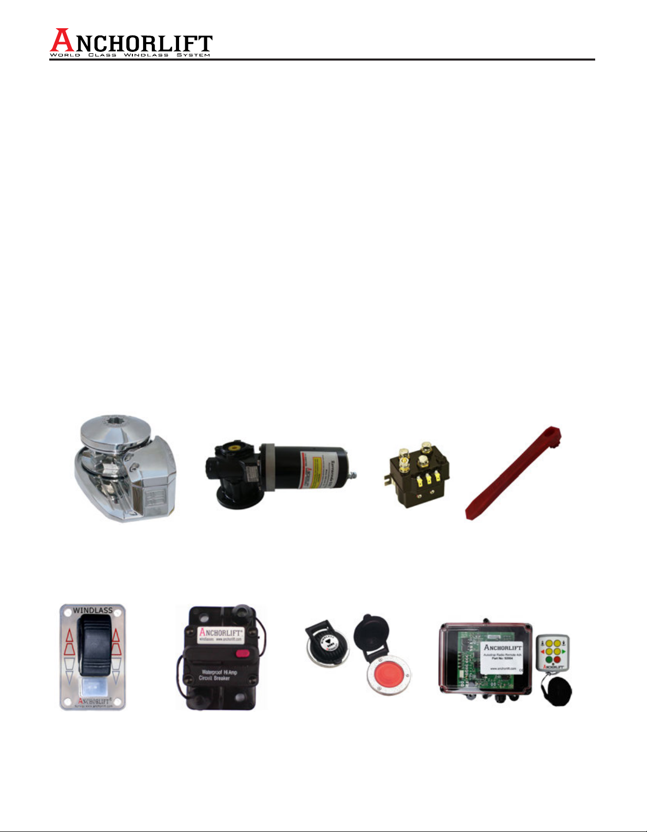
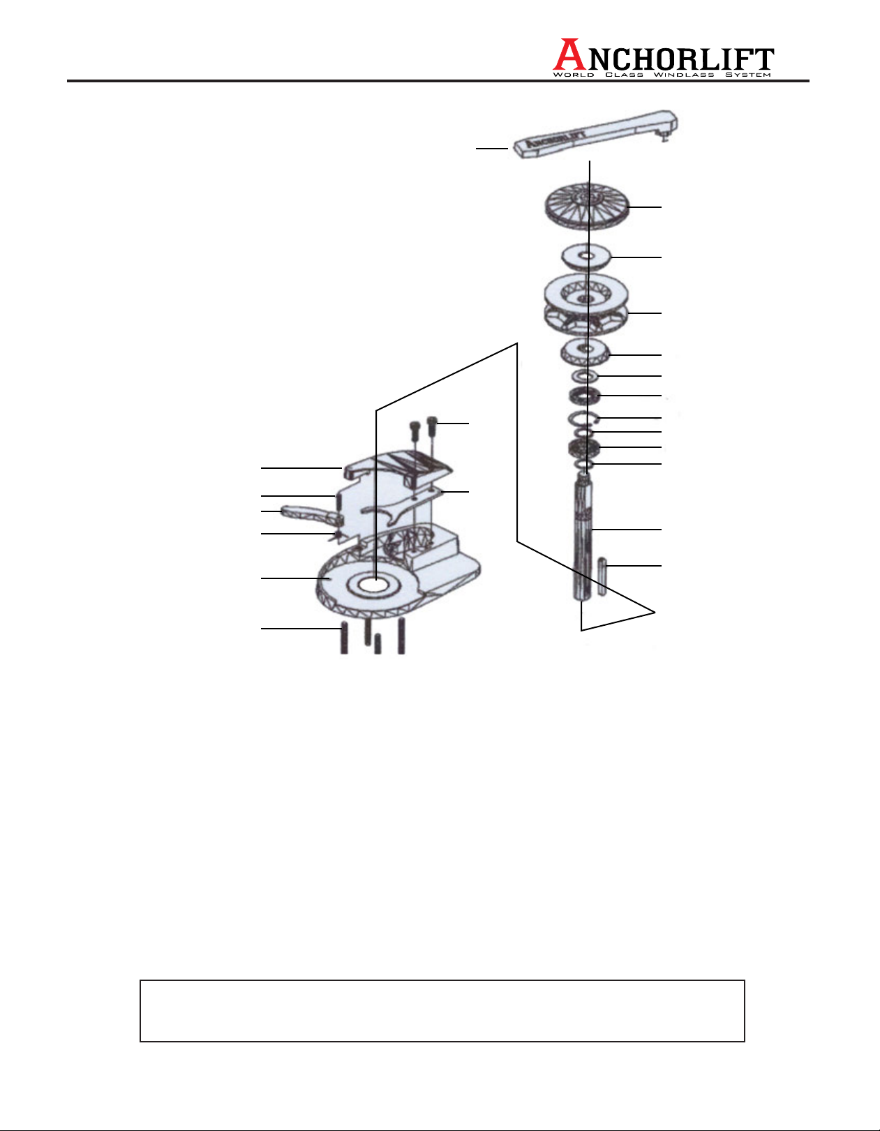
Make sure that the windlass shaft and gear box bushing are well greased with suitable marine grease before
installation (See photo P 1).
IMPORTANT!!
Protect the gear box and electric motor with suitable anti-corrosion spray such as CRC® Heavy Corrosion Inhibitor,
Corrosion X®, Tectyl® or similar product. See pictures P 1 & P 2.
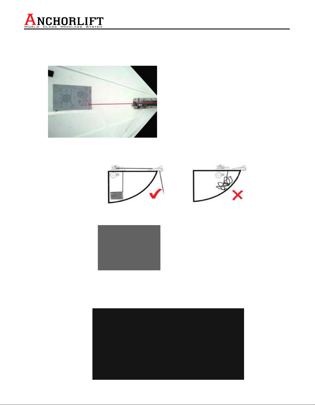
Make sure to position the windlass so that the center line of the chain / rope aligns with the bow roller in a horizontal
plane, and that the vertical line is within 10 degrees (See photo P 3) of the rope / chain gypsy.
Drill and cut out holes to the size detailed on the template. Make sure that the chain pipe hole is angled and smooth
to allow the chain / rope / rode kit to easily pass through it (See drawing P 4). Note: With a sandwiched deck
construction, it is important to seal the exposed surface.
NOTE: Care should be taken when installing the windlass to ensure that the vertical drop below the chain pipe exit is
maximized. Remember that rope coils unlike chain, and will require as much anchor locker space as possible (See
drawings P 6 and P 7).
Place the Windlass Deck Unit in position and connect the Gear Box/Motor. Fit the shaft into the Gear Box while
aligning the key into the keyway. Align the deck bolts to the holes in the gear box flange and push firmly to the
underside of deck. It may be necessary to move the motor/gear box up and down the shaft to make sure the grease
is completely covering the entire shaft. Apply thread locker to exposed threads and assemble with stainless steel
hardware supplied. After installation: Use anti corrosion marine protection on the motor and gearbox. See photo P 2.
Preparation:
The windlass is to be placed in the correct position by aligning the gypsy with the bow. The rope or chain needs to be
level with the deck and wound around the gypsy at an angle of about 180 degrees.
(See photo P 3)
Before drilling holes, you must check the following:
1) There are to be no obstacles below the deck. There must be enough space for the chain/rope (Rode Kit) to fall
properly 12-18 inches.
2) Make sure the top and bottom surfaces of the deck are as parallel as possible. If necessary, compensate for any
differences to prevent windlass base & gearbox from being damaged.
3) Once the ideal position has been found, place the drilling/mounting template in position and mark all the holes.
Barracuda, Dolphin & Mako models are equipped with 8mm stainless steel bolts. When installing the windlass use a
10mm drill bit for the bolt holes.
Before installing turn the windlass over and supply a suitable bead of sealant as shown below.
TM
Installation 3
www.anchorlift.com
P 3
P 5
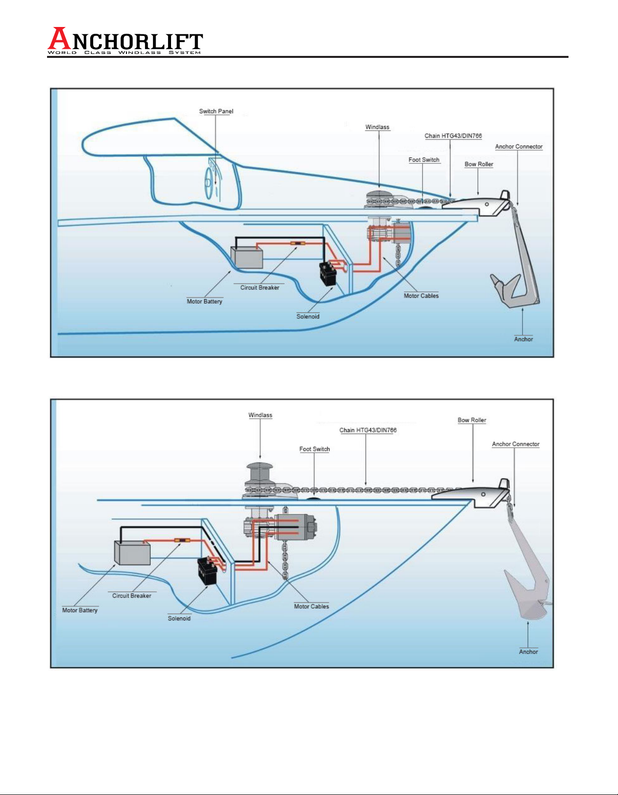
WIRING DATA:
ELECTRICAL: See the appropriate wiring diagram for the correct electrical installation of your windlass model.
WARNING!
Always use a circuit breaker to protect the windlass motor and electrical cables.
Cable sizes
We recommend the use of the following cables, switch-wiring and circuit breaker sizes:
P 6 P 7