ancnoble FMP-Solar User manual

1
1.General....................................................................................................................................................................................2
2.Specification........................................................................................................................................................................... 2
3.Function.................................................................................................................................................................................. 3
4.How to install..........................................................................................................................................................................3
4.1 Notes of installation:.......................................................................................................................................................4
4.2 Installation:..................................................................................................................................................................... 4
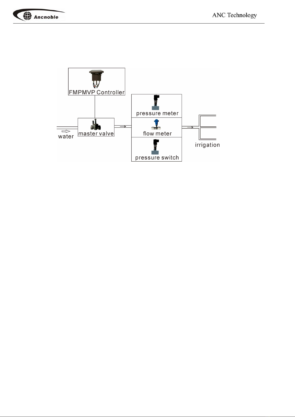
4.2.1 Pump connection illustration...............................................................................................................................4
4.2.2 How to install pressure sensor/switch................................................................................................................. 6
4.2.3 Valve connection..................................................................................................................................................7
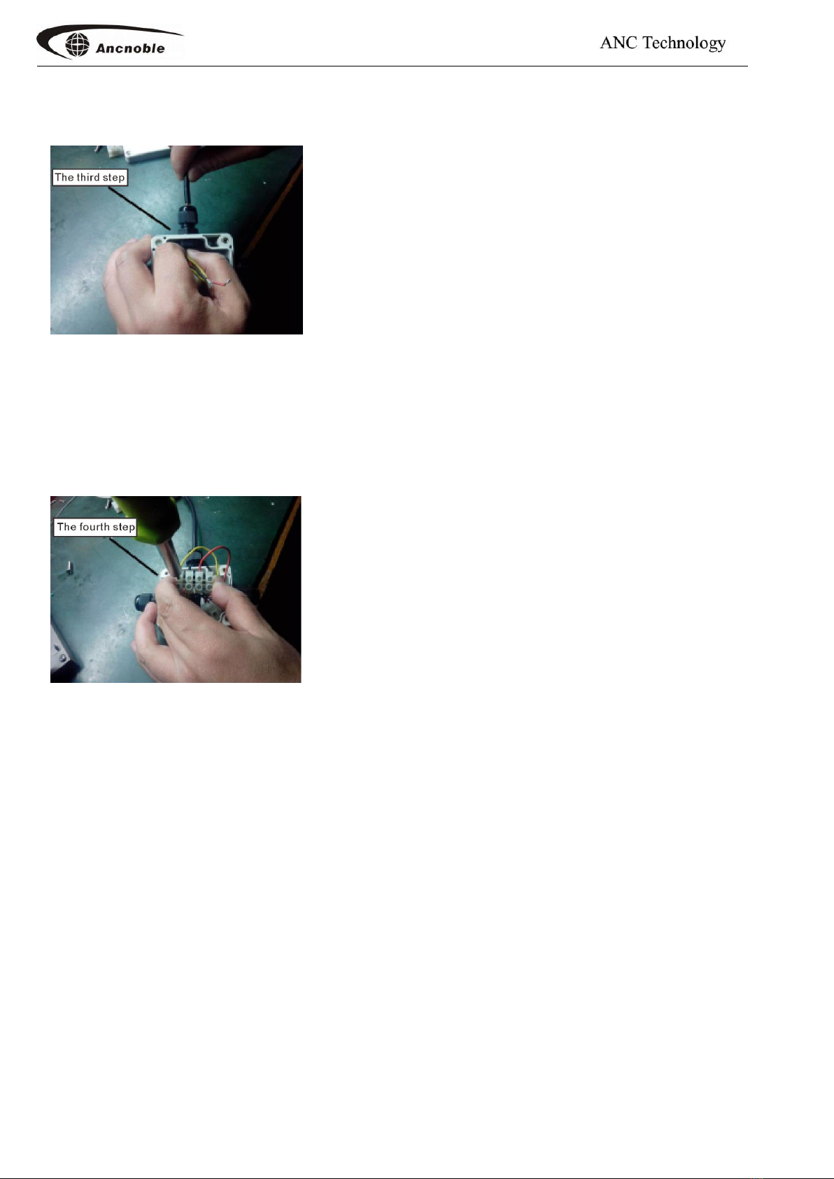
4.3 How to do connection inside the connection box.......................................................................................................... 8
4.4 Printed instruction on the box:..................................................................................................................................... 10
5.How to operate......................................................................................................................................................................10
5.1 Turn on Controller........................................................................................................................................................ 10
5.2 How to register to GG-002wifi/3g system main controller..........................................................................................11
5.3 How to establish wireless communication mesh network........................................................................................... 11
5.4 How to turn off controller.............................................................................................................................................13
5.5 Controller sleep.............................................................................................................................................................13
5.6 Field manual open/close............................................................................................................................................... 14
5.6.1 Field manual open/close....................................................................................................................................14
5.6.2 Field manual open/close pump..........................................................................................................................14
5.7 Explanation of LCD information..................................................................................................................................15
5.7.1 Main working LCD display:...........................................................................................................................15
5.7.2 LCD display for protective shut down of pump:............................................................................................16
5.7.3 Communication window:............................................................................................................................... 17
5.7.4 Detail information windows..............................................................................................................................17
6.How to setup......................................................................................................................................................................... 19
6.1 Flow Meter setup.......................................................................................................................................................... 19
6.1.1 Register/Remove flow meter.............................................................................................................................20
6.1.2 How to setup flow meter coefficient number....................................................................................................22
6.1.3How to setup flow rate range..............................................................................................................................22
6.1.4 How to clear total flow volume.........................................................................................................................23
6.2 Pressure meter setup..................................................................................................................................................... 24
6.2.1 Reg/remove pressure meter...............................................................................................................................24
6.2.2 Setup pressure range (0 - 1Mpa)....................................................................................................................... 24
6.3 Pump setup....................................................................................................................................................................24
6.3.1 Register and remove pump................................................................................................................................25
6.3.2 Set up pump protection sensor.......................................................................................................................... 25
6.3.3 Setup pump protective time delay.....................................................................................................................26
6.4 How to setup master valve............................................................................................................................................26
6.4.1 Register/Remove master valve..........................................................................................................................26
6.4.2 How to setup detection devices.........................................................................................................................27
6.4.3 Setup valve open/close time delay.................................................................................................................... 28
6.5 Help...............................................................................................................................................................................28
6.5.1 Questions and Answer....................................................................................................................................... 28
6.5.2 Communication link.......................................................................................................................................... 28
7. How to upgrade wireless field controllers..............................................................................................................................29

2
1.General
FMP-Solar controller controls pump and master valve, measures flow rate, and water
pressure. Compatible with GG-002 WiFi / 3G wireless control system.
Solar powered with water proof shell design, good for outdoor application.
2.Specification
Solar Panel: 17.4V DC /220mA/3.8W (Support Extra panel)
Back battery: 10*1.2V/ 2.3AH AA NiMH
Solar charging time: About 10 hours under standard sunlight
Idle power:1mA
Lasting time under fully charged battery: 7 days
Wireless frequency:902MHz-928MHz
Receiving distance: Open space ≧500 米,can relay forward.
Application environment:Temperature:-30~60℃Relative humidity:<90%
Flow meter specification:
1,Voltage:12VDC
2,Type:Turbine(3 wires system)
3,Signal:Pulse
Pressure meter specification:
1,Voltage:12VDC
2,Range:0-1Mpa
3,Signal output:Current4-20mA

3
Valve specification:
1,Voltage:6-12VDC Pulse
2, Latching valve
Pump control output:Open-(12VDC)Close-(0VDC)
Controller box size:Long:28cm Wide:17.5cm High:28.2cm
Controller box protective grade: IP56
3.Function
1,ASA weather proof shell design, water proof, for outdoor application
2,Solar powered, wireless, no need of power or communication lines in the field.
3,Solar panel is fixed on the shell. Can add extra solar panel for area without enough sun.
4,With relay function.
5,Control:pump and master valve, Monitoring flow rate, flow total, water pressure, and
water level of well or water tank.
6,Field manual open/close pump and master valve for convenience.
7,Setup flow rate and water pressure range to control protective shut down of pump and
master valve.
8,Using water level checking function to control protective shut down of pump, to avoid
pumping without right water level.
4.How to install
Please read manual before installation. We have how to install video online.

4
4.1 Notes of installation:
1,Make sure solar panel is face maximum sun. If there is not enough sun, add extra solar
panel.
2,For application of controlling pump and master valve, must install protective pressure
sensor or pressure switch. If pump water from well, suggest to sue water position sensor to
prevent pumping without water.
3,All accessories, suggest to using parts suggested on ANC web. If need to purchase from
another source, please communicate with ANC first to make sure it is compatible.
4,The connection box is water proof. Before cover up, make sure the rubber seal at right
position for seal and checking around to make sure all connectors are been tighten, including
connectors not been used.
4.2 Installation:
4.2.1 Pump connection illustration

5
How to install pump

6
4.2.2 How to install pressure sensor/switch
Note: Because that the threaded end of pressure sensor and switch is very small, suggest
using three way adaptor for small pipe, and drill hole to install for big pipe.
When water pressure out of setup range, the controller will protectively shut off the pump or
master valve.
If pump water from well ,suggest to install level sensor to protect pump from pumping
without water from well or rain tank. The setup will be one for high, and one for low. The
pump will not been open when the water level didn’t at high position. If the water reaches
low position, the controller will protectively shut down the pump.
Also could install flow meter, when the flow rate is out of range, the controller will
protectively shut down the pump and alarm.
“T” connection drilling connection

7
4.2.3 Valve connection
For master valve, choose one of them as protective devices, pressure switch, pressure sensor,
or flow meter. To mechanical pressure switch, must do tiny adjusting when water go through
pipe, adjusting the screw until no alarms at normal situation. (Open water proof cap to do
adjusting. Screwing in to increase pressure, screwing out to reduce pressure until there is no
open/close valve alarm).
For pressure meter, if the open water pressure is bigger than the setup pressure, as normal or
otherwise alarm; when pump/valve is been closed, pressure less than this setup value, as
normal or otherwise alarm.
Pressure meter and switch, must installed after water flow.
3, Connection for supervising flow rate and pressure.

8
There are only total 5 wireless flow meter controllers for one GG-002 WIFI/3G system.
4.3 How to do connection inside the connection box
Turn off controller first. Check printed instruction at both beside of the controller, find the
one you want to do connection. And pick out the related connector from the box. Unscrew
and get ready.
Step 1:Unscrew outside water proof screw.
Step 2:Take connector out of box。
Step 3:Screw loose water proof cap from the cable, take off plug, and insert wires into the

9
box.
Step 4: According to printed instruction on the side of the box, connect the wires according
to color, and screw tight.
Step 5:Double check connection, put seal right, before put the connector back to box.
Cover and tight up.

10
4.4 Printed instruction on the box:
Extra solar panel+Flow meter Valve+Pressure Meter+Pressure switch
Pump+Low Level switch+High level switch
5.How to operate
1. Solar panel 6.Battery 11. Manual valve key
2. LCD 7. Water proof connector 12. Enter/Save key
3. Key pad 8. Connection instruction 13. Browse/Menu key
4. Cable 9. Stick 14. Exit/Remove
5. Battery 10. Manual switch of pump 15. Digital keys
5.1 Turn on Controller
Push and lock the red power key at right low end of the controller, followed by two beep,

11
LCD will show as following, then into running. If the battery voltage is low, the controller
will turn self off.
If there is no sun to charge battery for some time, the battery voltage will reach low point,
then controller will protectively shut down self , and automatically wake up after the battery
is been recharged again.
5.2 How to register to GG-002wifi/3g system main controller
FMPVPP registration including 1. Flow meter, 2. Pressure meter, 3. Master valve, and
4.Pump.Needs registration to get system ID and code, to establish bidirectional wireless
communication between these devices and main controller.
Please read related charter of how to register.
5.3 How to establish wireless communication mesh network
After power been turn on, if all devises are already been registered, the controller will
automatically try to establish wireless communication route to reach main controller. During
searching time, keys been locked, push “Exit” to exit if needs, otherwise LCD shows
“Searching Comm path”. After route is been established, there will be two beeps, the
controller is ready for work.
If failed to establish the route, the controller will unlock the keys and back to previous menu
after 1 minute. Push digital key 4 you will see “X”, which means no route been established.
Please check and see if the distance is right, or if all the relay on the way is normal. If push

12
digital key 4 show“√”, which means the route is been established. You can check the route
by browsing into help menu.
This controller will automatically search route until success. Or push [Setting] key into main
menu, then push [Exit] key to exit will produce one search, if there is no wireless
communication route yet.
During search, the keys are been locked up. LCD show as following:
After successfully established route, the FMVPP field controller will send the route
information to main controller. If done, main controller will show “ ” icon on related
LCD screen, FMVPP route show as “√”. If failed to establish route, will show “ ”,and
try again every one minute, if tried three times without success, the controller will think the
route has been tried is not right, change route and try again.
Note 1. For speed up establishment of wireless mesh network, please follow steps as below:
A. Register all the field controllers first. Then turn off all the field controllers.
B. During search time, the main controller must be in normal work status at registration
status, not in any programmable menu, ready to pick all field wireless signals.
C. Take the main controller as center, turn on field controllers which are most nearby, like in
the range of 500meter or 1640feet, more or less, then all field controllers been on, start
automatically looking for route to communicate with main controller. After all this layer of
controllers found route to main controller, then open second layer of field controllers in the
mesh work, so on until all 4 layers of controllers all established wireless communication with

13
main controller.
Note 2: All field controllers need to found wireless route through relay to communicate with
main controller, the relay route could be 1, 2, or 3 layers. Field controllers will report route to
the main controller, the main controller then save this information and follow this route to
communicate with field controllers. After the field controllers found the route, will keep send
the route information to the main controller every one minute, if tried three times without
success, will looking for another route.
Note 3: If the established route no more working, the controller will automatically search
new route after one hour try.
5.4 How to turn off controller
Push the red power switch will turn power off。
5.5 Controller sleep
During working period, controller will check the voltage of battery time to time. When the
backup battery voltage reach less than 11 V, the controller will turn off master valve and
pump, stop flow meter, put self into sleep, waiting for the solar panel to recharge the battery.
When the battery voltage is been charged back to 11.5 V, the controller will automatically
back to working status. During sleep period, if the solar panel still can’t charge up the battery,
if the backup battery voltage drops to 10 V, for protecting the battery from over discharge,
the controller will automatically turn from sleep status to total turn off.
After been total turn off, the solar panel will still charge the battery as long as there is sun.
Controller will automatically wake up after the battery is been changed up to normal.

14
During sleeping, LCD show as following:
5.6 Field manual open/close
5.6.1 Field manual open/close
During working status, push “valve” key ,LCD show valve status as “Manual on”,the
controller will open the master valve, and send current status to main controller.
Push “valve” key again, LCD show status as “Manual off”,which will manually turn off
valve.
“valve” key has cycling function, cycle function as “Auto off-Manual on-Auto off-
Manual off”,Every push switch function.
After manual open /close operation, the controller will keep this manual status until
manually switch to either auto on or off from the field controller, then go back to auto
control.
During manual open/close status, the controller will keep beep to reminder user to switch
back to auto control after field work finished.
5.6.2 Field manual open/close pump
Same as field valve manual open/close, reference 5.6.1。

15
After manually open the pump, LCD show as above. 05'( time range is 00'-99')means
manual open valve for 5 minutes. This function is for observing delay time needed for
stabilizing flow rate and water pressure, then setup right delay time for alarm. And setup
right flow and pressure range.
5.7 Explanation of LCD information
5.7.1 Main working LCD display:
1,Pump status:Above LCD show display as “Auto off”, which means current status is auto
off. Pump has 6 status, Auto off、Auto on、Manual off、Manual on、Remote on、Remote off.
2,Master valve status:Above show as “Auto off”, which means current status as auto off.
There are 6 status as, Auto off、Auto on、Manual off、Manual on、Remote on、Remote off。
3, Current flow rate and accumulated total flow volume. Total flow volume alarm shown as
icon, before the flow rate. The icon will not show until this alarm function is been enabled.
If this function is been enabled, there is “ ” icon. First alarm show “ ”, second alarm show
as “ ” icon.

16
This function is for fertilizing control by total flow volume. Customer setup first and second
alarm volume from main controller or PC. For example, like 3 cubic meter and 4 cubic meter.
Then, when the volume reached 3 cubic meter, first alarm on, it is time to start get ready to
turn off the valve, when reached 4 cubic meter, second alarm on, it is time to turn off the
fertilizing valve.
After valve been turned off, flow rate reach to 0, this flow meter controller will automatically
finish this cycle of fertilizing alarm.
Suggested connection:
4,Current pressure meter reading
5.7.2 LCD display for protective shut down of pump:
When pump is been protective shut down, LCD will show the reason, 1, High flow rate +
value of the high flow rate; 2, Low flow rate + value of the low flow rate; 3, High pressure +
value of high pressure; 4 Low pressure + value of low pressure; 5, Low water level.
Above example show information as, auto shut down by low flow rate at 0.00 m³/h.

17
5.7.3 Communication window:
During communication time between FMP-Solar and main controller, show as above. Then
all the keys been locked up until communication finished.
5.7.4 Detail information windows
During normal work status, push【1】【2】【3】【4】digital keys switch for more work
information. Also can push【Enter】key,switch and cycle information window.
Push key【1】,show flow meter information,
Flow meter registration #:Here show as 1,which means registered as #1 flow meter in this
system. (Otherwise, show as, “Not registered”).
Flow rate:Show current flow rate. Can setup different unit at basic setup.
Show total flow volume.
Pus key【2】,show pressure information
1. Pressure meter registration #:Here means this pressure meter registered as #1 pressure

18
meter in this system. (If not registered yet, will show ”Not registered”)。
2. Current pressure。
3. Pressure range:Pressure range setup by customer.
Push key【3】,show valve and pump information
1. Master valve registered #:Here #1 means this master valve is been registered as #1
master valve in this system. (If not registered, will show “Not registered”).
2. Master Valve:The status are:Auto off、Auto on、Manual off、Manual on、Remote on、
Remote off。
3. Pump #:Same as master valve.
4. Pump status:Same as master valve.
Push key【4】,showID/route and wireless signal strength
System ID:FMP-Solar controller through registration to get ID from the main controller. All
field controllers in one system have same ID.
2. Current battery status. Will show charging icon when is charging.
3. Show communication status. Route without relay show as ”√”, with relay show as ” ”,
or no route with ”×”。

19
4. Strength of wireless signal.
Note:The controller will automatically turn off after 1 minute without any operation. Push
any key to bring back.
6.How to setup
This controller control one flow meter, one pressure sensor, one pump and one master valve.
Each has setup menu. Push【Menu】into main menu, push 【Menu】again to browse. Push
【Enter】into the setup. Push【Exit】key to exit or exit without operation after 1 minute.
6.1 Flow Meter setup
For flow meter, there are 4 setup as: Reg(istration)/remove flow meter –Setup flow rate
range –Clear total flow volume to zero. Push
【Menu】
key to browse, push
【Enter】to confirm.
Push【Exit】key back to previous menu, or return after 1 minute without operation.
Table of contents
Other ancnoble Measuring Instrument manuals
Popular Measuring Instrument manuals by other brands

Tektronix
Tektronix RSA6100B Series instructions

David White
David White AL8-22 instruction manual

EUTECH INSTRUMENTS
EUTECH INSTRUMENTS CYBERCOMM PRO FOR CYBERSCAN CON 1500 instruction manual

Agilent Technologies
Agilent Technologies E4418B Service guide

Topcon
Topcon GTS-230 Series instruction manual

Lumel
Lumel ND25 user manual

Elcometer
Elcometer 311 user guide

PCE Health and Fitness
PCE Health and Fitness VOC 1 user manual

Berkeley Varitronics Systems
Berkeley Varitronics Systems Wireless Multi-band Signal Meter System Wolf product manual

Fieldpiece
Fieldpiece JL3MN user manual

Agilent Technologies
Agilent Technologies NFA Series Setup guide

Fluidwell
Fluidwell F126-P-EL-TP manual