AND AD-1690 User manual

1WMPD4002043D

© 2015 A&D Company Ltd. All rights reserved.
No part of this publication may be reproduced, transmitted, transcribed, or translated into
any language in any form by any means without the written permission of A&D Company
Ltd.
The contents of this manual and the specifications of the instrument covered by this manual
are subject to change for improvement without notice.

3
CONTENTS
1. INTRODUCTION .................................................................................................................4
1.1. Compliance .....................................................................................................................4
2. FEATURES..........................................................................................................................5
3. PART NAMES/CONSTITUTION.........................................................................................6
3.1. Main Unit .........................................................................................................................6
3.2. Accessories.....................................................................................................................6
4. CONFIRMING BEFORE USE..............................................................................................7
5. MEASUREMENT PREPARATION.......................................................................................8
6. KEY OPERATION .............................................................................................................10
7. MEASUREMENT...............................................................................................................11
8. CHANGING THE JUDGMENT CONDITION......................................................................13
9. FUNCTION ........................................................................................................................15
10. MAINTENANCE AND NOTES...........................................................................................18
11. RS-232C INTERFACE ......................................................................................................22
12. SPECIFICATIONS .............................................................................................................24
12.1.Optional Accessories and Separately Sold Accessories ................................................24
12.2.Dimensions ...................................................................................................................25

4
1. INTRODUCTION
This manual describes how the AD-1690 Leak Tester works and how to get the most out
of it in terms of performance.
Read this manual thoroughly before using the Leak Tester and keep it at hand for future
reference.
1.1. Compliance
1.1.1. Compliance with FCC Rules
Please note that this equipment generates, uses and can radiate radio frequency energy.
This equipment has been tested and has been found to comply with the limits of a Class
A computing device pursuant to Subpart J of Part 15 of FCC rules. These rules are
designed to provide reasonable protection against interference when the equipment is
operated in a commercial environment. If this unit is operated in a residential area, it may
cause some interference and under these circumstances the user would be required to
take, at his own expense, whatever measures are necessary to eliminate the interference.
(FCC = Federal Communications Commission in the U.S.A.)

5
2. FEATURES
This Leak Tester judges a leak by a pressure change, after the initial pressure is set
inside the instrument, to a maximum of -20 kPa ±4 kPa.
The Leak Tester can verify a leak in a small instrument easily (Example: Micro pipette.
etc).
The amount, -20 kPa, attained by evacuating the air with the Leak Tester, is approximately
0.2 atmospheres (based on atmospheric pressure at sea level).
(100 kPa is approximately 1 atmosphere (based on atmospheric pressure at sea level).)
This Leak Tester is a tool for judging leakage, and it cannot measure pressure values
accurately. The Leak Tester displays -20 kPa as a reference pressure and measures
leakage as a pressure change from this amount.
This Leak Tester is designed to test the leakage of a pipette or dispenser and prevent
foreign particle from invading the Leak Tester when evacuating the air at the nozzle of
the instrument.
This Leak Tester is protected against invading dust by an air filter located on the main
unit bottom side.
The accessories provide attachments for four different pipettes tip sizes.
You can select an attachment where the tip and pipette size match up.
With the Micro pipette, the available test capacity is up to 10000 μℓ.

6
3. PART NAMES/CONSTITUTION
3.1. Main Unit
3.2. Accessories
Power supply adapter
Note
Please confirm that the AC adapter type is corrected
for your local voltage and receptacle type.
Adapter and Attachment
Display
Keys
RS-232C
interface
Plug for accessory
adapter opening: left
(Connector hole [1])
AC adaptor jack
Main unit
bottom side
Air filter unit
(Inside: Air filter element)
Main unit
Plug for accessory
adapter opening
: right
(Connector hole [2])
AC adapter
ID label
For micro pipette
with more than 5000
μℓ to less than
10000 μℓ
For micro pipette with more than
20 μℓ to less than 200 μℓ
For micro pipette with 1000 μℓ
For micro pipettes of less than 10 μℓ
For 10 μℓ or smaller micro pipettes when other
attachments do not fit.
Adapter
Attachment
(Large)
Attachment
(Medium)
Attachment
(Small)
Attachment
(Smallest)
Connection tube
(Main unit side)
Disconnect button
Connector
Tip
Tip
Tip
Tip
Connector
Connector
Connector
Connector
Connector

7
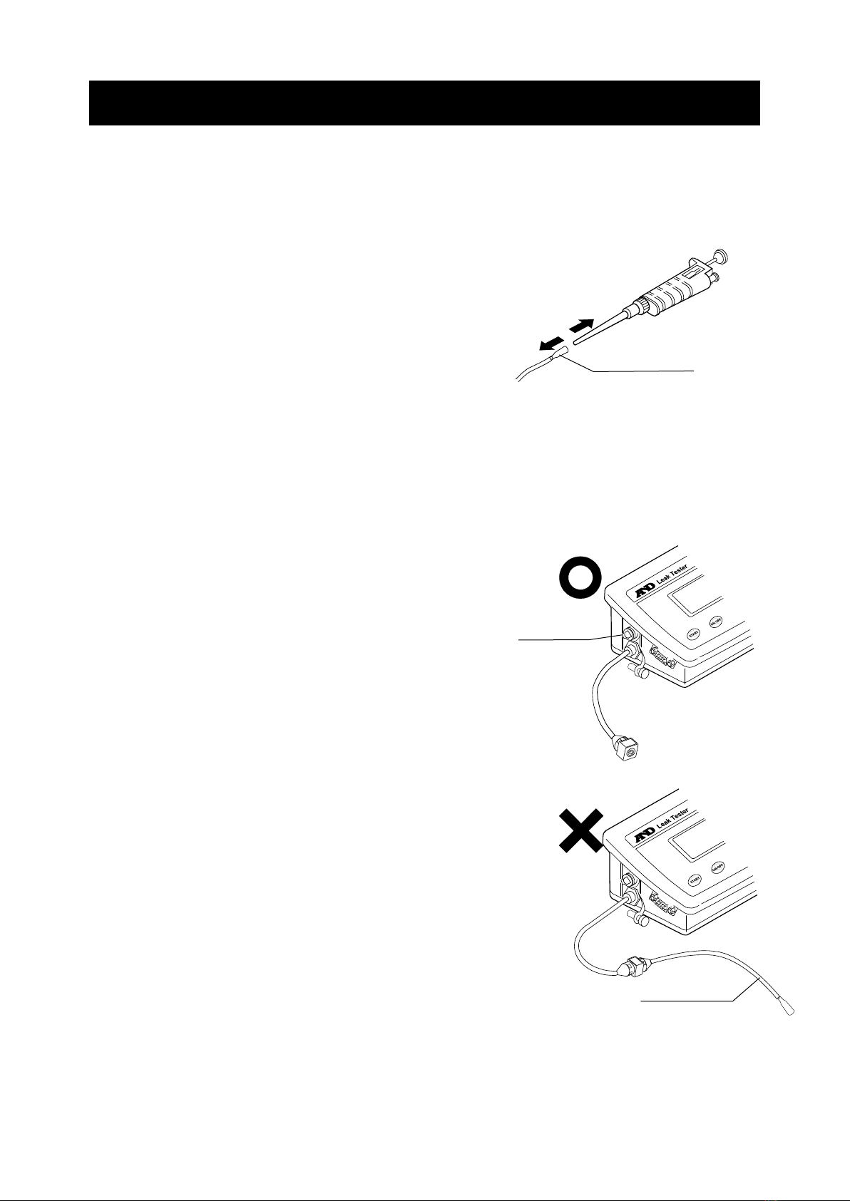
4. CONFIRMING BEFORE USE
(1) Confirming the main unit
With following state, confirm that the right
and left air plugs (
parts) are pushed in
the connector holes firmly.
Confirm that the filter unit is installed
in the holder located on the main unit
bottom side correctly.
(2)Confirming the operation
1.Connecting the ac adapter to the main unit
Open the AC adapter jack cover located on the
side of the main unit, insert the AC adapter
plug into the AC adapter jack. Plug the AC
adapter into an appropriate electrical outlet.
Note
- Please confirm that the AC adapter type is
correct for your local voltage and receptacle type.
- The AC adapter plug is protected against dust and may be difficult to insert.
When inserting the plug, turn the plug while pushing on it.
2.Main unit conformation
Press the ON:OFF key. The display is “ ” (that means READY) and the
Leak Tester is in the measurement standby mode.
With the right and left air plugs installed, press the START key.
When displaying “ ” after operating the pump, the instrument is operating
normally.
When displaying “ ”, confirm that the right and left air plugs, and the filter unit
located on the main unit bottom side are connected correctly.
When not solving the “ ” display, there may be a leak inside Leak Tester. Contact
the local A&D dealer for service.
After confirming, return the inside pressure of the Leak Tester to atmospheric
pressure by removing either the right or left air plug. (If an air plug is not removed,
the pressure inside the instrument remains in a state of vacuum.) When not starting
another measurement immediately, reconnect the air plugs and close the cover on
the AC adapter jack, to avoid dust from invading the main unit.
Main unit
bottom side
AC adapter
8
5. MEASUREMENT PREPARATION
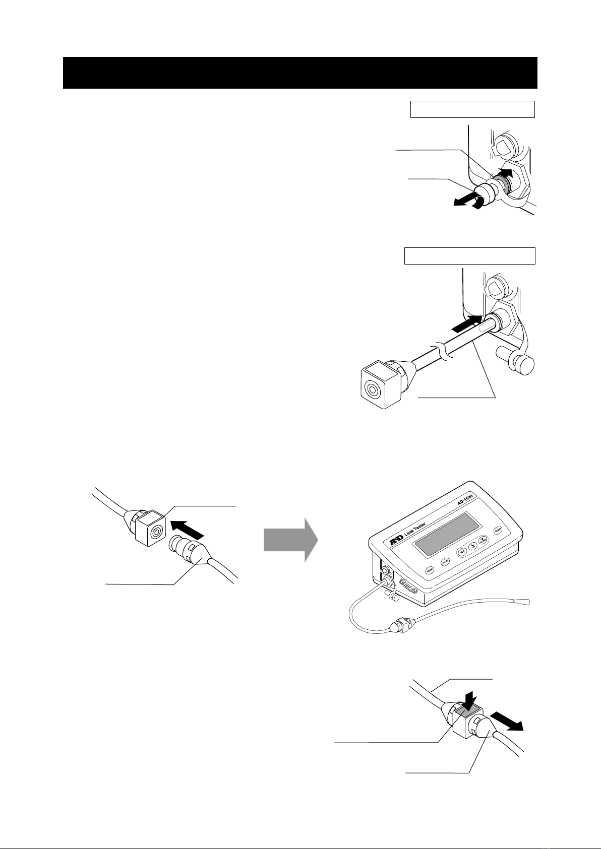
(1)Connecting the adapter (tube) to the main unit
Remove the air plug located on either side of the main
unit. Connect the tube of the adapter to the main unit.
* The air plugs and the adapter tube are connected by a
coupling having a lock function. When removing the air
plug or tube, while pushing on the release ring located
on the connector opening (1), pull it out (3) after pushing
the air plug or tube lightly (2).
* When connecting, confirm that the air plug or adapter tube
is pushed in the connector hole firmly.
(2)Connecting the attachment (pipette side)
The accessory attachments provided have four different pipettes tip sizes. Select the
attachment in order that the tip and pipette size match up, then connect the
attachment to the adapter.
* When replacing the attachment, remove it by
pushing the disconnect button (blue part).
Attachment
Adapter
1
2
Attachment
Adapter
Disconnect button
1
2
3
Push the
r
elease ring
Push in and pull out
Air plug
Removing the air plug
Adapter tube
Connecting the adapter
9
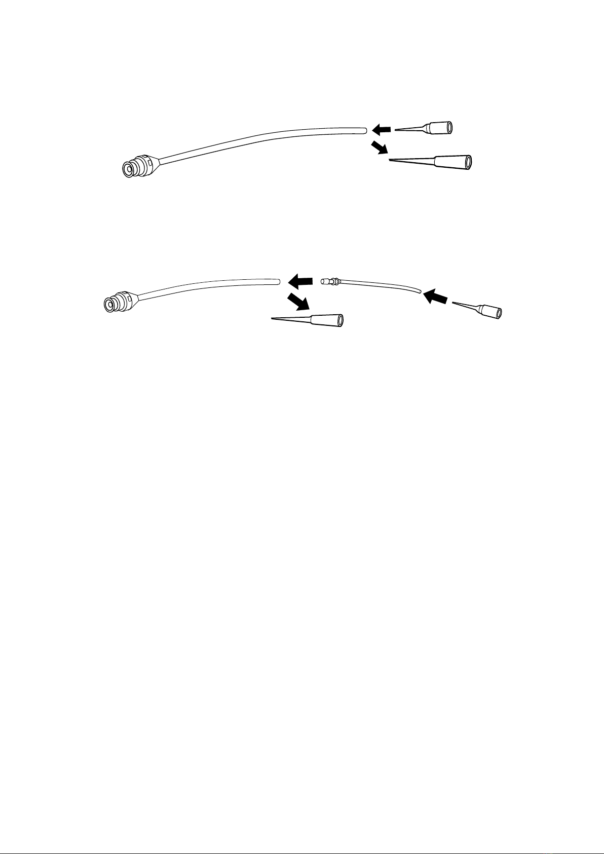
Replacing the tip provided with the attachment
When the tip provided with the attachment does not match the pipette to be tested,
replace the tip with a suitable tip.
Using the connection tube
If the replacement tip cannot be connected directly to the attachment tube due to its
shape, then use a connection tube to connect to the attachment tube.
(3)Connecting the ac adapter to the main unit
Open the AC adapter jack cover located on the side of the main unit, insert the AC
adapter plug into the AC adapter jack. Plug the AC adapter into an appropriate
electrical outlet.
Note
- Please confirm that the AC adapter type is correct for your local voltage and
receptacle type.
- The AC adapter plug is protected against dust and may be difficult to insert.
When inserting the plug, turn the plug while pushing on it.
Attachment
(Large/Medium/Small/Smallest)
Tip provided
Replacement tip
Connection tube
Replacement tip
Tip provided
Attachment
10
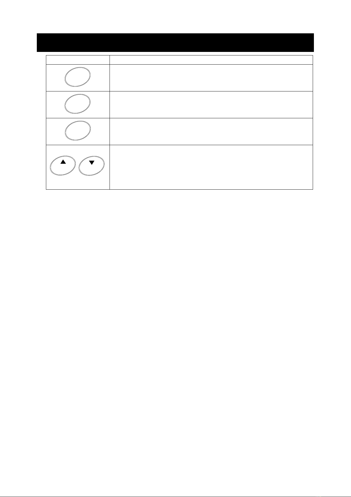
6. KEY OPERATION
Key
Description
Turns the power supply of the main unit on and off.
These keys are in two positions, to the right and left.
These two keys
have same function. Start (or stop) the
measurement.
Enter the setting mode by pressing and holding for 2 seconds.
Store the setting condition that was changed by pressing.
When setting the mode, change the setting value (the quantity
of pressure change and monitor time of the leak judgment
condition).
When using “UP”, the value is increased. When using “DOWN”,
the value is decreased.
ON:OFF
START
SET
UP DOWN
11
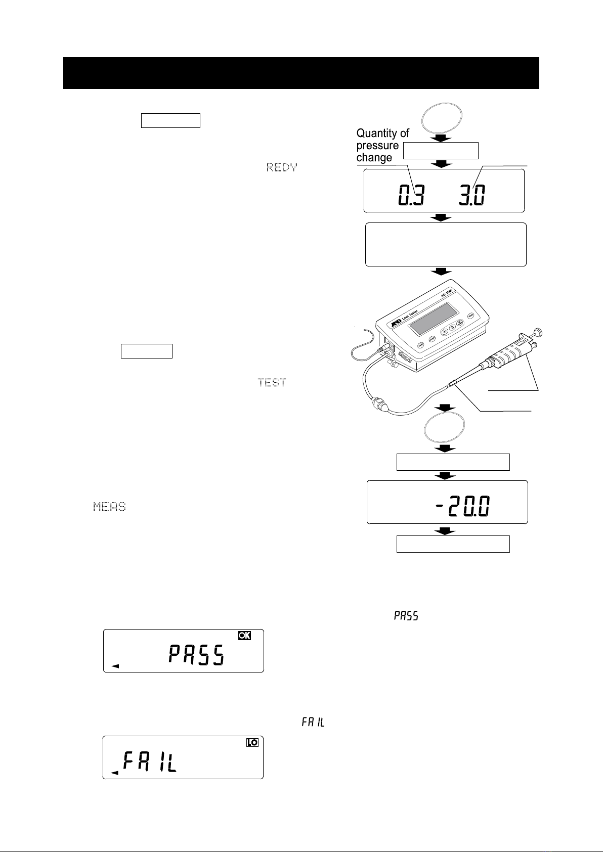
7. MEASUREMENT
(1)Power supply
Press the ON:OFF key (The display is
“display all”). After displaying the setting value
(quantity of pressure change and monitor time
for leak judgment), the display is “ ” (that
means READY) and is in the measurement
standby mode.
(2)Starting measurement
Connect the test pipette to the tip of the
attachment securely.
Press START key. The main unit starts the
measurement by operating the pump,
evacuating the air to -20 kPa. (“ ” display)
When -20 kPa is reached, the pump stops.
* -20 kPa is approximately 0.2 atmospheres that
means that the air has been partially evacuated.
* While stabilizing the inside pressure, the display
may change by 0.1 to 0.2 kPa.
The main unit measures the quantity of the
pressure changed by the monitor time set.
(“ ”display)
* Factory setting: monitor time is 3 seconds,
quantity of pressure changed is +0.3 kPa.
(3)Measurement result
When the quantity of pressure change with leakage is in less than the setting value,
the Leak Tester judges that there is no leak and displays “ ” (normal).
When the pressure, with any leakage does not reach -20 kPa or when the quantity of
pressure change is over the setting value after reaching -20 kPa, the Leak Tester
judges that there is a leak and displays “ ” (abnormality).
Pipette
Tip
Monitor
time
kPaS E C
ON:OFF
REDY
All displayed
START
TEST kPa
Measurement starts
Measurement result
12
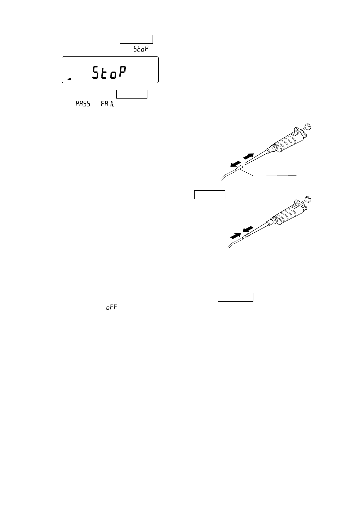
When pressing the START key, while in the middle of a measurement, the
measurement stops and “ ” is displayed.
When pressing the START key again, the Leak Tester judges the measurement
result (“ ”/“ ”) after operating the pump again.
When finishing the measurement, remove the pipette
from the tip of the attachment.
If the pipette has the ejector (for releasing the tip),
remove the pipette by operating the ejector.
When measuring another pipette, press the START
key again after connecting the pipette to be measured
(return to “(2) Starting measurement”). The leak tester
starts the measurement. At this time, the display is the
measurement result.
* When kept in a state of having the air evacuated,
in the case of not removing the pipette, the pump
does not operate again.
(4) Measurement end
When finishing the pipette measurement, Press the ON:OFF key to turn the power
supply off (after “ ” is displayed, the power supply turns off). Then, disconnect the
AC adapter from the main unit.
For storing, refer to “10. MAINTENANCE AND NOTES”.
Attachment
Pipette
13
8. CHANGING THE JUDGMENT CONDITION
You can change “quantity of
pressure change” and “monitor time”
if necessary to set the conditions
for judging if there is a leak or
no leak. When canceling the
setting halfway, press the
ON:OFF key to turn the
power supply off.
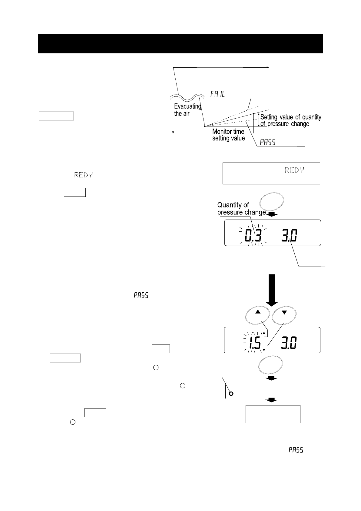
(1)Changing the setting value
When “ ”*(that means READY) or the
measurement result* is displayed, press and hold
the SET key (Approx. 2 seconds).
The main unit displays the setting value of the
quantity of pressure change flashing (left side of
the display) and the monitor time (right side of the
display).
* Refer to “(1) ” and “(3)” of “7. MEASUREMENT”.
(2)Changing the quantity value of pressure change
After evacuating the air, when the pressure
changing is more than the setting value, the Leak
Tester judges a leak and “ ” is displayed.
The Leak Tester judges the leak by the quantity
value of pressure change of the pressure increase.
(Unit: kPa)
Changing the minimum value is by 0.1 kPa.
(Factory setting: 0.3 kPa)
Change the value by using the UP or
DOWN key.
* The value displayed with the “ ” mark (left side
of the display) is the value in memory. But, while
changing the displayed value, the “” mark
turns off.
Press the SET key to store the value.
(The “ ” mark turns on, at the left side of the display)
After the quantity value of pressure change stops flashing,
the monitor time value (right side of the display) is flashing.
* If the quantity value of pressure change is insufficient when measuring, “ ” may
be displayed by changing the measurement system pressure (Leak Tester, adapter,
attachment).
Time
-20 kPa
Judgment of no leak
“” display
Judgment of leak
“”display
Pressure
When displaying “ ” or
the measurement result
Monitor
time
Press and hold
kPa SEC
SET
Turning on
Press
UP DOWN
kPa S E C
SET
kPa
Store
Changing the
monitor time

14
(3)Changing the monitor time
The leak tester judges the leak by the monitor time.
(Unit: second)
Changeable by 0.5 seconds up to 100 seconds, and
by 10 seconds over 100 seconds up to 990 seconds.
(Factory setting: 3.0 seconds)
Change the value by using the UP or DOWN key.
* The value displayed with the “ ” mark (left side
of the display) is the value in memory. But while
changing the displayed value, the “” mark is
turned off.
Press the SET key to store the value.
After setting finishes, “ ” is displayed
for approximately 1 second (the “ ” flashes).
(4)End of setting
The Leak Tester returns to the measurement standby
mode by non-operation, or by pressing the SET
key, to memorize the setting value changed with “(2)”
and “(3)” above.
(5)Initializing the setting value
When displaying* “ ” of (3), press the DOWN key
at once.
* Refer to “(3) Changing the monitor time”.
After displaying “ ”, “ ” is displayed.
If you want to initialize, press the
UP or DOWN key to change
to “ ”, and press the SET key.
After the setting value returns to the
value initialized (quantity of
pressure change: 0.3kPa, monitor
time: 3.0 seconds), the display
returns to measurement standby
mode (“ ”display).
If you do not want to initialize, when displaying the
“ ”, press the SET key.
The display returns to measurement standby mode
(“ ”display) after displaying “ ”.
REDY
Not
initialize
Press
Press
Initialize
confirming display
SET
SET
UP DOWN
SET
SET
SET
DOWN
SET
Press
Initialize
Press
Store
SET
kPa SEC
SET
UP
DOWN
15
Press
and
hold
Press
(2) Selecting the mode of
the function (item)
(4) Setting mode
Displaying the procedure
for measurement result
Serial interface
output format
Go to A) of (4)
Go to B) of (4)
Leak Tester is in
the m
easurement
mode.
To function
(3)
(3)
(3)
ON:OFF
SET
DOWN
UP
DOWN
UP
SET
SET
SET
FUNC
FUNC
FUNC
FUNC
UP
DOWN
9. FUNCTION
Set the function by the following procedure.
(1)Entering the function
With the power turned off, press and hold the
SET key and press the ON:OFF key,
to turn the power on.
After displaying “ ”, “ ” (flashing)
is displayed.
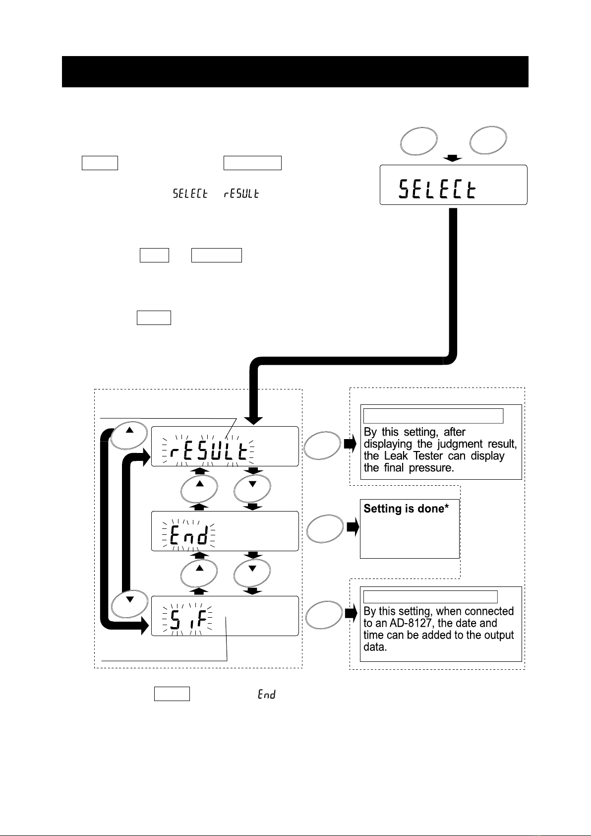
(2)Selecting the mode of the function (item)
Press the UP or DOWN key to select the item
of the function. (Refer to the figure on the left bottom)
(3)Entering the setting mode
Press the SET key to enter the setting mode with
the item selected. (Refer to figure on the right bottom)
* Press the SET key while “ ” is flashing.
16
(4)Setting mode
A) Selecting the procedure for measurement result
- The procedure is displayed.
- Press the UP or DOWN key to select
either or .
: After measurement, Leak Tester display
the only judgment result ( or ).
: After measurement, the Leak Tester
displays the final pressure after
displaying the judgment result.
- Press the SET key to store the setting.
The display is in the next setting mode.
( or )
* Factory setting:
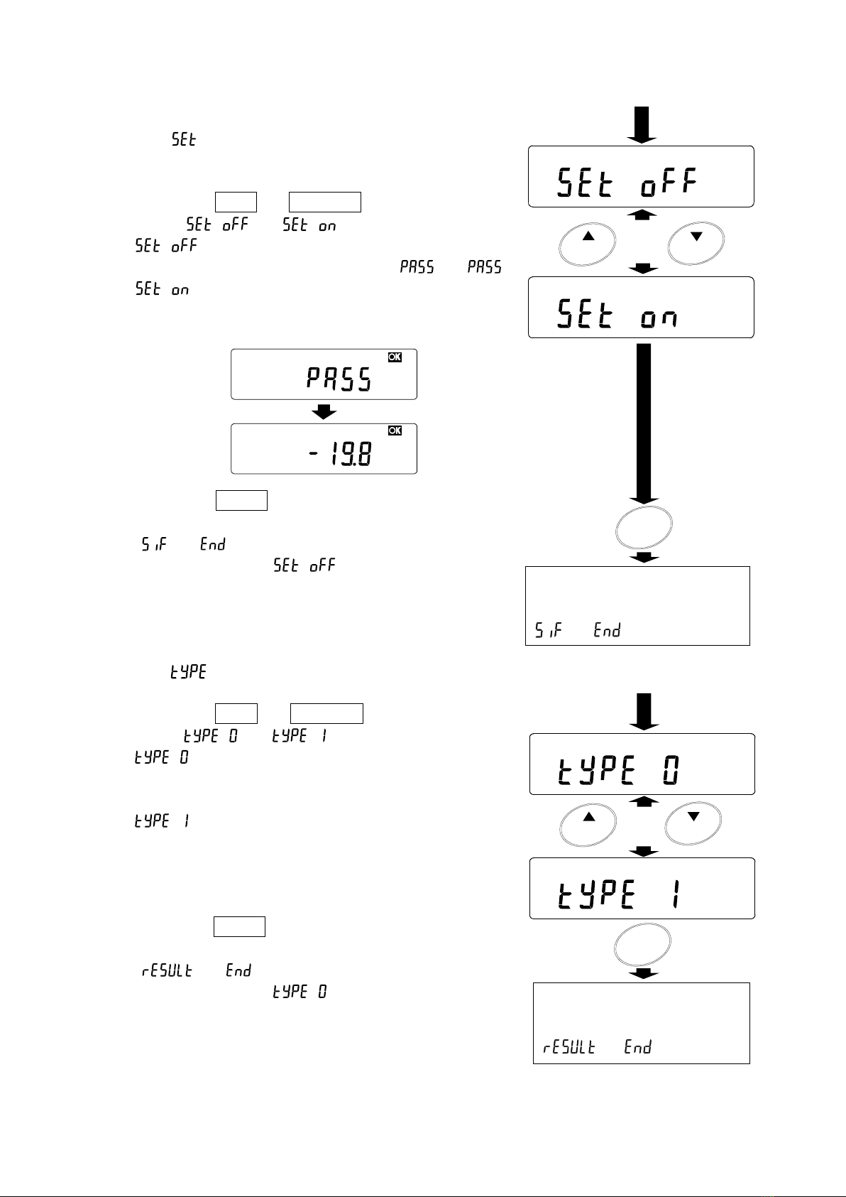
B) Setting the output format of the serial interface
-The procedure is displayed.
-Press the UP or DOWN key to select
either or .
: The setting to connect the Leak
Tester to either an AD-1688,PC,
or AD-8127.
: The setting to output the date and
time by an AD-8127.
(The date and time are added
before each data set)
- Press the SET key to store the setting.
The display is in the next setting mode.
( or )
* Factory setting:
Approx. 1 second
PASS kPa
DOWN
UP
SET
SIF P C
SIF Prn
Continued from (3 on page 13)
or
Press
The setting is stored in
memory. The display is in
the next setting mode
( or ).
Continued from (3 on page 13)
The setting is stored in
memory. The display is in
the next setting mode
( or ).
or
Press
DOWN
UP
SET
RESL
RESL

17
Print sample
: :
Sample printed with AD
-
8127 Sample printed with AD
-
8127
* The date and time of the print sample use the internal clock of the AD
-
8127.
Set the AD
-
8127 date and time if necessary.
* The AD
-
1690 can send a special code for printing the date and time.
Therefore, set to “ ”, when connecting the AD
-
1690 to instruments other than
the AD
-
8127.
Setting of the AD
-
8127
When using with either or , set the AD
-
8127 to “Dump printing mode”.
Setting Info.
00.3kPa/03.0s
PASS -19.9kPa
FAIL -03.5kPa
DATE 2010/02/26
TIME 16:31:13
Setting Info.
00.3kPa/03.0s
DATE 2010/02/26
TIME 16:31:29
PASS -19.9kPa
DATE 2010/02/26
TIME 16:32:08
FAIL -03.5kPa
18
10. MAINTENANCE AND NOTES
(1)Removing the attachment
After measurement, remove the pipette and accessory by the following procedure.
When storing the main unit, allow of the Leak Tester to equalize to atmospheric
pressure.
1) Remove the pipette from the attachment.
2) Remove the attachment from the adapter.
At this time, if the attachment is still connected
to a pipette, the inside pressure of the Leak
Tester will not return to atmospheric pressure.
(2)Storing
When storing the leak tester, avoid dust from invading the main unit and connector
tube (adapter, attachment). Close the cover of the AC adapter jack.
1) Adapter
Dust cannot enter the main unit when connected
to the accessory adapter. The connector has the
airlock function. Therefore, the Leak Tester is
protected from invading dust.
But if the connector part of the adapter becomes
dirty, dust may invade at the next measuring.
2) If the attachment is connected to the adapter,
dust may invade through the attachment. When
storing, remove the attachment.
Attachment
Pipette
Adapter
AC
adapter jack
Attachment
19
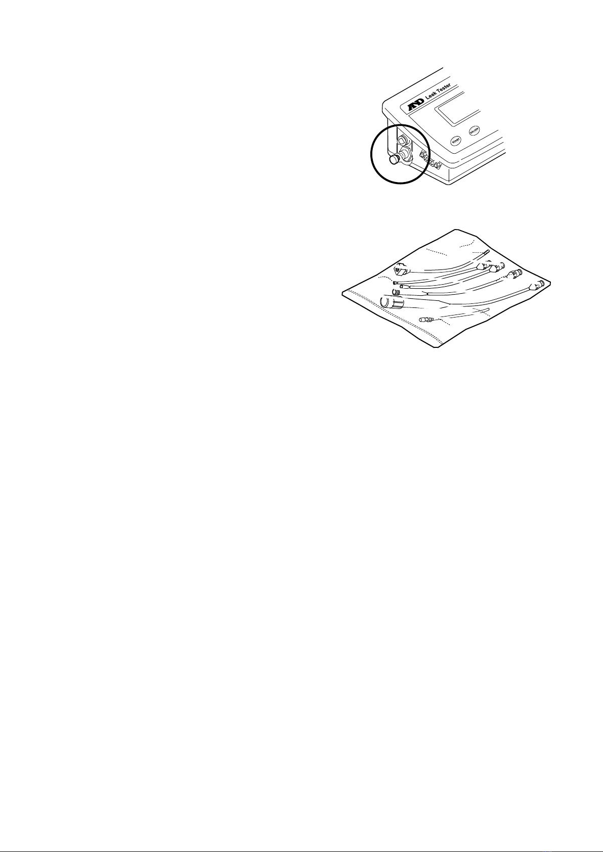
3) Main unit
Push the cover in the AC adapter jack and push
the air plug in the connector hole (right and left
side), so that dust cannot invade the main unit.
4) Storing the attachment, adapter and connection tube
Store the adapter and attachments in
the sealed bag. They will be protected
from invading dust.
20
(3)Exchanging the filter
The inside of the main unit is protected from invading dust by the air filter located on
the main unit bottom side. Check the main unit regularly, replace the filter element or
filter unit if necessary.
Turn the power supply of the main unit off by removing the AC adapter. And after
returning the inside of the leak tester to atmospheric pressure by removing the pipette,
follow this procedure.
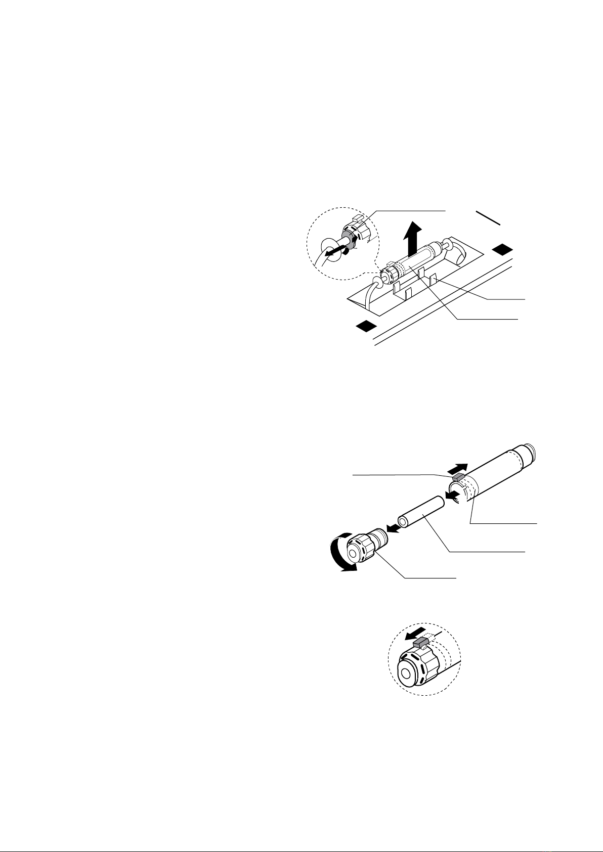
1) Removing the filter unit
Invert the main unit and remove the
filter unit from the holder.
Pull the tubes out from both sides
of the filter unit.
(At this time, while pushing the
release ring lightly, pull the tube
out after pushing it in lightly.)
2) Replacing the filter element
When replacing only the filter element, follow this procedure:
1. Slide the red slide lock located on the
filter unit in opposite direction of the
arrow.
2. Turn the coupling in a counterclockwise
direction (180 degrees).
3. Remove the coupling from the filter
cover. Remove the old filter element
from the coupling.
4. Clean the dust from inside the filter
cover, if necessary.
5. After connecting the new filter element
to the coupling, insert it into the filter
cover. Last, turn the coupling in a
clockwise direction.
6. Confirm that the positioning of the
detent located on the coupling and the
slide lock match up and slide the slide
lock in the direction arrow. Confirm that
the coupling is securely locked.
Main unit
bottom side
1
2
Filter unit
Release ring
Holder
6
Coupling
Filter element
Filter cover
Slide lock
1
2
5
3
Other manuals for AD-1690
1
Table of contents
Other AND Test Equipment manuals


