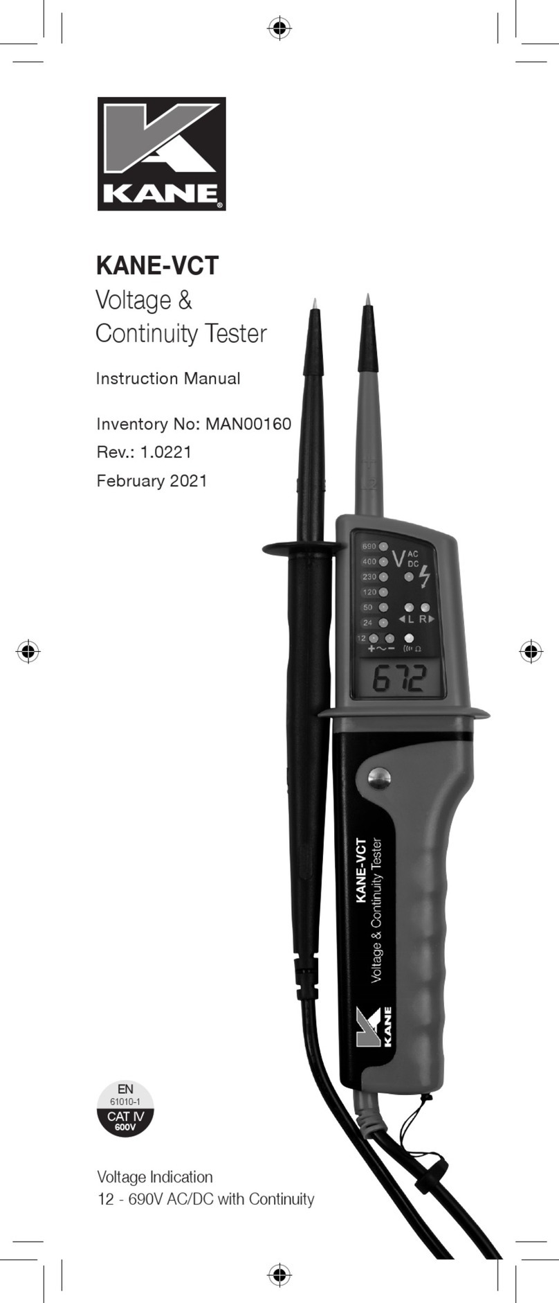
Kane 501C User manual

KANE501C
Performance Tester
Stock No: 18708-2 June 2012
Registered Community Design No: 001051940
© Kane International Ltd

KANE501C Manual Page 2
CONTENTS
Page No:
1. GETTING STARTED 3 - 6
1.1 SAFETY 3
1.2 PRE-TEST CHECKLIST 3
1.3 STORING INLET TEMPERATURE 4
1.4 SELECTING FUEL 4
1.5 ANALYSER CONNECTIONS AND ZEROING 5
1.6 POST TEST 5
1.7 OVERVIEW 6
2. MAINTENANCE 7 – 9
2.1 GENERAL MAINTENANCE 7
2.2 PERIODIC SERVICE 7
2.3 ANNUAL RE-CALIBRATION 7
2.4 CLEANING 7
2.5 WATER TRAP 8
2.6 CHANGING PARTICLE FILTER 8
2.7 BATTERY REPLACEMENT 8
2.8 ELECTROMAGNETIC COMPATIBILITY 9
3. COMBUSTION INFORMATION 10
3.1 PROBLEM SOLVING 10
4. GLOSSARY 11 - 13
4.1 SELECTOR AND DISPLAY PARAMETERS 11
4.2 SPECIFICATIONS 13

KANE501C Manual Page 3
OWNERS MANUAL & MAINTENANCE
1. Getting Started
1.1 Safety Notes
Before using this analyser, read all safety information carefully. In this
manual the word “WARNING” is used to indicate conditions or actions
that may pose physical hazards to the user. The word “CAUTION” is
used to indicate conditions or actions that may damage this instrument.
WARNING!
This analyser extracts combustion gases that may be toxic in relatively
low concentrations. These gases are exhausted from the back of the
instrument. This instrument must only be used in well-ventilated
locations. It must only be used by trained and competent persons after
due considerations of all the potential hazards.
1.2 Pre-test Checklist
Clean particle filter
Water trap and probe are empty of water
All hose and thermocouple connections are properly secured
Flue gas probe is sampling ambient FRESH air
Water trap is fitted correctly to the instrument
Flue temperature plug is connected
1.3 Storing Inlet Temperature
To correctly calculate net temperature and combustion efficiency it is
important to have the correct inlet temperature set. Two methods are
available to properly establish the inlet temperature.
Non-ducted Systems. If the KANE501C is being used on a system
that uses combustion air from the space near the appliance, simply
turn the analyser on without the flue probe connected. The
KANE501C will use an ambient sensor inside the handset as the
inlet temperature to determine net temperature.

KANE501C Manual Page 4
Ducted Systems. If the KANE501C is being used on a system that
brings in outside air for combustion air it is important to set up the
inlet temperature prior to taking flue gas readings. To properly set
inlet perform the following steps during start-up of the KANE501C:
1. Connect the flue temperature connector only to the KANE501C.
2. Place the flue probe in the combustion air inlet system
3. Turn on and allow to complete the zero process.
4. Connect the flue gas connector and proceed to combustion
measurements.
5. The temperature measured during the zero countdown has now
been stored, and will be used to determine the net temperature.
1.4 Selecting Fuel
When powering on, simply rotate the selector to the desired fuel. The
display will flash this on the display, and then it will complete the zero
process.
NOTE: If you wish to use the same fuel as previously selected rotate the
selector to “Stand By” at power on. The fuel in use will be displayed and
then blink. If the fuel is not correct rotate the selector to the proper choice
before the zero countdown starts.
1.5 Analyser Connections and zeroing
NOTE: Take care when inserting the temperature probes as the pins are
polarized.
CAUTION!
Turning the pump off while the probe is in the flue will leave toxic gases
inside the analyser. Once data has been read, it is advisable to purge the
unit with fresh air as soon as possible. Always allow the readings to
return to zero (0.0 for CO2) prior to shutting the unit off.
CAUTION!
The probe will be hot from flue gases. Remove the probe from the flue
and allow it to cool naturally. Do not immerse the probe in water, as this
will be drawn into the analyser and damage the pump and sensors. Once
the probe is removed from the flue and the readings have returned to

KANE501C Manual Page 5
ambient levels rotate the selector to “OFF” and switch off the analyser.
The instrument will count down from 10 to switch off.
CAUTION!
To optimise the measuring accuracy of the instrument, a zero should be
performed after the first 20 minutes of use (either with the pump running
or in the standby position). To do this, remove the probe from the
flue/exhaust port, or disconnect the hose from the gas inlet on the
analyser and turn the analyser off and on again in fresh air.
1.6 Post Test
Remove the probe from the flue and allow the analyser to purge
with fresh air until readings return to zero. (Be careful as the probe
tip will be HOT)
Drain water trap.
Check particle filter.
WARNING!
This meter does not measure Carbon Monoxide (CO). Only measuring
CO
2
does not indicate whether a combustion process is running fuel rich
or fuel lean. A fuel rich combustion process can produce potentially
dangerous levels of CO so other measurements must be made to ensure
that the combustion process is running fuel lean and that the CO levels
are acceptably low.

KANE501C Manual Page 6
1.7 Overview
Fuel/ Test
Type Indicator
Water Trap
LCD Display
Selector Dial

KANE501C Manual Page 7
2. Maintenance
2.1 General Maintenance
Check calibration of your instrument annually to ensure it meets
original performance specifications.
Keep your instrument dry. If it gets wet, wipe dry immediately.
Liquids can degrade electronic circuits.
Whenever practical, keep the instrument away from dust and dirt
that can cause premature wear.
Although your instrument is built to withstand the regions of daily
use, it can be damaged by severe impacts. Use reasonable caution
when using and storing the analyser.
2.2 Periodic Service
CAUTION!
Repair and service of this instrument is to be performed by qualified
personnel only. Improper repair or service could result in physical
degradation of the instrument. This could alter the protection from
personal injury this analyser provides to the operator. Perform only those
maintenance tasks that you are qualified to do.
2.3 Annual Re-Calibration
While the sensors have an expected life of more than five years in
normal use it is recommended that the analyser is re-calibrated at least
annually, this is so that long-term drift on the electronics can be
eliminated. Local regulations may require more frequent re-calibration
and users should check with appropriate authorities to ensure they
comply with relevant guidelines.
2.4 Cleaning
Periodically clean your instrument case using a damp cloth. DO NOT use
abrasive, flammable liquids, cleaning solvents, or strong detergents as
they may damage the finish, impair safety, or affect the reliability of the
structural components.

KANE501C Manual Page 8
2.5 Emptying and Cleaning the In-Line Water Trap
The integral water trap should be checked and emptied on a regular
basis. Water vapour will condense in the probe line, which may cause
the water trap to fill suddenly if the probe is moved. Care should be taken
at all times.
Carefully unscrew the plug from the bottom of the
water trap housing. Dispose of the condensate in a
suitable drain, care must be taken as it could be
acidic. If condensate spills onto the skin or clothing,
clean off immediately using fresh water, seek
medical advice if problems occur. Ensure plug is
replaced before performing combustion tests.
NOTE: CO
2
reading will be low if the Water Trap Plug is not in place.
2.6 Changing the Particle Filter
This is a very important part of the analyser and should be changed
regularly. It prevents dust and dirt particles from entering the pump and
sensors that will cause damage. The filter MUST be changed when it
appears discoloured.
Remove water-trap assembly from the analyser as
shown above. Remove the filter and plastic holder
from the housing. Discard the filter element but keep
the holder to fit to the new filter. Clean the inside of
the filter housing with a suitable soft cloth. Fit the
holder onto the new filter element and then insert into
the housing. Refit the housing onto the analyser.
2.7 Batteries Replacement
This meter has been designed for use with alkaline
batteries. No other types are recommended. The
analyser is supplied with 4 “AA” size alkaline batteries.
These should be installed into the instrument as shown
in the diagram to the right and indicated on the back of
the unit.

KANE501C Manual Page 9
CAUTION!
Take great care when installing the batteries to observe the correct
polarity. Always check the meter for operation immediately after installing
new batteries.
2.8 Electromagnetic Compatibility (EMC)
The European Council Directive 89/336/EEC requires that electronic
equipment does not generate electromagnetic disturbances that exceed
defined levels and has an adequate level of immunity to enable it to be
operated as intended.
Since there are many electrical products in use that pre-date this
Directive and may emit electromagnetic radiation in excess of the
standards defined in the Directive there may be occasions where it would
be appropriate to check the analyser prior to use. The following
procedure should be adopted.
Go through the normal start up sequence in the location where the
equipment is to be used.
Switch on all localised electrical equipment that might be capable
of causing interference.
Check that all readings are as expected. (A level of disturbance in
the readings is acceptable)
If not, adjust the position of the instrument to minimise interference
or switch off, if possible, the offending equipment for the duration of
the test.
At the time of writing this manual (December 2008) KANE is not aware of
any field base situation where such interference has ever occurred and
this advice is only given to satisfy the requirements of the Directive.
This product has been tested for
compliance with the following generic
standards:
EN 50081-1
EN 50082-1
and is certified to be compliant.

KANE501C Manual Page 10
3. Combustion Information
3.1 Problem Solving
If any problems are not solved with these solutions, contact us or an
authorised repair centre.
Fault Symptom Causes / Solutions
CO
2
too low Air leaking into probe, tubing, water
trap or connectors.
Meter does not respond to
flue gas
Particle filter blocked.
Probe or tubing blocked.
Pump not working or damaged with
contaminants.
Net temperature or Efficiency
calculation incorrect
Ambient temperature set wrong
during Automatic Calibration.
Flue temperature readings
erratic
Temperature plug reversed in
socket.
Faulty connection or break in cable
or plug.
T flue or T net displays (----) Probe not connected or faulty.
X-Air, EFF display (----) CO
2
reading is too low.

KANE501C Manual Page 11
4. Glossary
4.1 Selector and Display Parameters on KANE501C
“2Er0” – Analyser is performing the initial zero setting.
CO
2
(Carbon Dioxide) – Direct reading of the Carbon Dioxide Sensor
displayed in percentage (%)
Eff (Efficiency) – Calculated combustion (not appliance) efficiency based
on measurements of CO
2
, Flue Temperature and fuel selected. The
KANE501C calculates nett combustion efficiency and automatically
determines if the combustion is in the condensing mode to make
appropriate corrections.
X-Air (Excess Air) – Excess Air is calculated for each fuel type from the
CO
2
measurement. It assumes that the combustion process is running
fuel lean. It is important to make other measurements to confirm that this
assumption is always correct.
O
2
(Oxygen) – O
2
is calculated for each fuel type from the CO
2
measurement. It assumes that the combustion process is running fuel
lean. It is important to make other measurements to confirm that this
assumption is always correct.
TFlue (Flue Temperature) – TFlue is a direct measurement of the
temperature at the tip of the flue probe. This measurement is used to
determine the net temperature for use in calculation of the combustion
efficiency.
TNet (Net Temperature) – Differential temperature of TFlue and ambient
(or inlet if set)
BAT symbol – Displays the Battery Power available.

KANE501C Manual Page 12
Fuels Available
Selector Position Display Type
L Oil LOIL Light Oil
Propane PrOP Propane
Nat Gas nGAS Natural Gas
H Oil HOIL Heavy Oil
Wood wOOd Wood
Coal COAL Coal

KANE501C Manual Page 13
4.2 Specifications
(NOTE: MAY BE SUBJECT TO CHANGE)
Parameter Resolution Accuracy Range
Temp Measurement
Flue
Temperature
0.1 °C ± 2°C ± 0.3%
Reading
0-600°C
Temp (Nett)
*2
0.1°C ± 2°C ± 0.3%
Reading
0-600°C
Gas Measurement
Carbon Dioxide
*1
0.1% ± 0.2% 0-20%
Oxygen
*2
0.1% - 0-25%
Efficiency
*2
0.1% - 0-110%
Excess Air
*3
0.1% - 0-250%
Pre-Programmed Fuels Natural Gas
Light Oil
Propane
Wood
Heavy Oil
Coal
Dimensions (Approximate)
Weight
Handset
Probe
0.5 kg
175 x 45 x 80mm
6mm diameter x 250mm long Stainless
Steel Shaft with 1m long Neoprene Hose
Ambient Operating Range 0°C to 45°C
10% to 90% RH Non-Condensing
850 to 1100 mbar Atmospheric Pressure
Battery Life 4 AA Cells
> 8 Hours using Alkaline AA Cells
*1
Using Dry Gases at STP
*2
Calculated
*3
Calculated Assuming Fuel Lean Combustion

KANE501C Manual Page 14

KANE501C Manual Page 15

KANE501C Manual Page 16
Thank you for buying this
instrument.
Before use,
please register on our
website
www.kane.co.uk
This manual suits for next models
1
Table of contents
Other Kane Test Equipment manuals