AND WEIRO WP 40 A Product guide

1
MANUAL BOOK
WP 40 A
DC INVERTER AIR PLASMA
CUTTING MACHINE
Jalan Arif Rahman Hakim 51 Ruko 21 Blok D-1, Surabaya
0851-0199-2232 | 031-5990089 |031-5997259 | [email protected] | adnsby.co.id

2
Input
Output
1-phase rectifier HF inverter HF transformer Rectifier & filter
Control circuit
HF arc start
1-
GENERAL REMARKS
1-1
Cutting machine features
This CUT series inverter air plasma cutter is kind of energy-saving metal cutting equipment with high efficiency
and light weight, adopts single tube IGBT HF inverter and advanced control technology. Its advantages are fast
speed, narrow & clean cut, small heat-affected zone, slightly deforming, material-saving, low cost, simple
operation and so on. These cutterspossess good static and dynamic characteristics, perfect control function, and
high-frequencyarc starting function. The characteristics are as follows:
-
Single phase power supply, small size, light weight and easy to operate;
-
Air filter pressure-reducing valve is built-in type, portable and easy to use;
-
Highly centralized arc energy, good stability, strong cutting ability;
-
Fast cutting speed (3~5 times of gas cutting), low cost;
-
Narrow, burnished, clean and almost vertical cutting edge;
-
Less work piece deformation;
-
Continuous adjustment of cutting current;
-
HF arc ignition, easy arc starting;
-
Strong power grid adaptability and low noise;
-
Multiplepatented technology, high reliability and durability.1-2 Functional
principle
This series of cutting machines adopts HF inverter technology. 1- phase input volt is
rectified by rectifier, inverted by inverter composed of single tube IGBT into HF AC,
reduced by HF transformer, rectified and filtered by HF rectifier, then output DC power suitable for cutting.
This progress increases the dynamic response capability, reduces the weight and the size of the
transformer and the reactor, improves the efficiency of
the machine, realizes energy-saving.
The special design of control circuit makes the machines enjoy high cutting
performance despite of changes like power grid voltage fluctuation, cutting cable
length. Features include easy arc starting, narrow, burnished and clean cutting edge, and continuously
adjustable cutting current.
Schematic diagram is shown in Fig. 1-2-1:
Fig. 1-2-1: Schematic diagram

3
1-3
Output characteristics
Fig.1-3-1: Output characteristics
1-4
Duty cycle
Duty cycle is percentage of 10 minutes that a machine can weld at rated load without overheating. If overheats,
thermostat(s) will close, output stops. Wait for fifteen minutes for themachine to cool down. Reduce amperage or
duty cycle before welding.
NOTE! Exceeding duty cycle can damage unit and void warranty.
Fig. 1-4-1: Duty cycle
U (V)
Uo
U
=
80
+
0
.
04I
80
0
Imin
Imax
I (A)
60
CUT40i
40
31
0
10 20 30 40 50 60 70 80 90
100
% DUTY CYCLE
Overheating
Minute
0
OR
Reduce Duty Cycle
15
WELD AMPERES

4
DANGEROUS!
WARNING!
Read the operating manual carefully before
installation.
Only qualified electricians may install and
operate.
ELECTRIC SHOCK can kill.
Keep the welder and work place in
good grounding.
GASES AND FUMES can be
dangerous & hazardous to your
health
Keep adequate ventilation,
anti-dust and exhaust
ARC RAYS, Spatter can injure
eyes and skins.
NOISE can cause permanent
hearing loss.
Wear protective clothing and
welding shield with filter.
FIRE, EXPLOSION can be
caused by hot slag, spatter and
sparks.
Remove combustibles from
working area.
Provide fire watch as well as fire
appliance in the working area.
Re ad th e o p er at i n g ma nu a l
c a re f ul l y b e f or e i n s t a l l a t i o n.
D AN G ER O U S ! WA R N IN G
O n l y q u a li fi e d e l e c t ric i a n s m a y
in s t a l l a n d o p e ra te .
EL E C T R I C S H O C K c a n k il l.
G A S E S A N D F U M E S c a n be
da n g e r ou s & h a z a rd o u s
to
y ou r
he a l th
Ke e p t h e w el d e r a n d w o r k p l a c e in
Ke e p a d e q u at e v e n ti l a ti o n , a n ti -d u s t
go o d gr o u n d i n g . an d ex h a u s t
A R C R A Y S, S p at te r
c an
in j u r e
ey e s
FI R E , E X PL O S I O N c an be c a u s e d by
an d s k i n s . hot s l ag , s p a tt e r a n d
s p a rk s .
N O I S E
c an
c a us e
p er m a n e n t
h ea r in g
Re m o v e c o m b u s ti b l e s f ro m w o r k i n g
loss. a rea.
W e ar p ro te c t i v e cl o th i n g and we l d in g
Pr o v i d e f ir e wa tc h a s wel l a s f i r e
s h ie l d w it h fi lt e r. ap p l i a n c e in t h e w o rk i n g
ar e a.
1-5
Applications
It can cut stainless steel, carbon steel, alloy steel, aluminum, copper, nickel and
titanium.
The cutting machine is designed for the following recommend areas:
-
Maintenance and repair
-
Steel construction
-
Metal shop
-
Office furniture supplies
-
Daily civil occasions
1-6
Warning label
The warning label is affixed onto the top of the cutting machine, and it must not be
removed or painted over.
Fig. 1-6-1: Warning label

5
2-
VERSIONS BRIEFS
Professional cutting of special materials requires special cutting parameters. Different
models of the power sources are matched to different cutting.
CUT40i
This series of cutting machine is small, light and portable. Adopt single tube IGBT HF
inverter technology, can perform fast speed cutting with clean and almost vertical
cutting edge.

6
3
- BEFORE COMMISSIONING
Warning! Operating the equipment incorrectly can cause serious injury and damage.
Do not use the machine until you have read "Safety rules".
3-1
Utilization for intended purpose only
The cutting machine may only be used for cutting. Utilization for any other purpose, or
in any other manner, shall be deemed to be “not in accordance with the intended
purpose”. The manufacturer shall not be liable for any damage resulting from such
improper use.
Utilisation in accordance with the “intended purpose” also comprises:
-following all the instructions given in this manual;
-performing all stipulated inspection and servicing work.
3-2
Machines set-up regulations
According to test, protection degree of this power source is IP23S. However, the
internal key components must be protected from direct soaking.
Warning! Amachine that topples over or falls from its stand can easily kill someone.
Place machine on an even, firm floor in such a way that it stands firmly.
The venting duct is a very important safety feature. When choosing the machine location,
make sure it is possible for the cooling air to enter and exit unhindered through the louvers on
the front and back of machine. Any electroconductive metallic dust from e.g. grinding-work
must not be allowed to get sucked into the machine.
3-3
Cutting machine connection
-
The cutting machine is designed to run on the mains voltage given on nameplate.
-
The mains cables and plugs must be mounted in accordance with the relevant technical
standard.
-
The power supply socket come with power source is designed to use strictly according to
the marked voltage.
Note! Incorrect electrical installations can lead to protection fails or partial fails. The
mains plug and socket, and its fuse protection, must be suitable for local power
suppl
7
Cutting
machine
Air
compressor
Ground
cable
Plasma
torch
4-
CUT40i
4-1
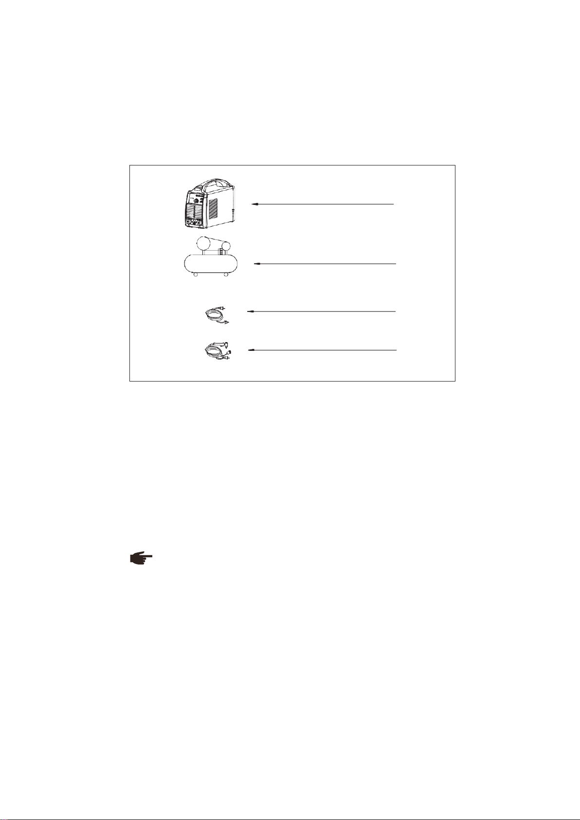
System components
This series of cutter can be equipped with many different accessories and can be used
in various sites with different configurations. (Refer to Fig. 4-1-1)
Fig. 4-1-1: System components
4-2
Basic equipments for cutting
Basic equipments are needed for normal cutting. Below are the lists:
CUT
-
Cutting machine
-
Ground cable
-
Plasma torch
-
Air compressor
4-3
Interface
The functions on the control panel are all arranged in a very logical way. The various
parameters needed for cutting are easy to select by pressing the appropriate button.
(Refer to Fig. 4-3-1)
Note! Your machine has certain functions that are not in accordance with this
operating manual, or vice versa. Also, certain illustrations may be slightly different
from the actual controls on your machine. However, these controls function in exactly
the same way.

8
1 2
3
7
4
5
25
30
CUT40i
35
20
15 40
CURRENT
(
A
)
9
6
8
Warning! Operating the equipment incorrectly can cause series injury and damage.
Do not use the functions described here until you have read and completely
understood this operating manual.
Front panel
Fig. 4-3-1: Front panel
1. Power on indicator
It is green light, indicates whether cutting machine is connected well to power supply. It lights
up when power on.
2. Gas pressure indicator
It is yellow light, does not light up during normal cutting; when input gas pressure of cutting
machine is lower than 0.35MPa, cutting machine will stop working automatically, protection
indicator lights up.
3. Over heat/fan locked-rotor protection indicator
It is yellow light, does not light up when cutting machine works normal. It lights up when inner
temperature is too high or fan is locked-rotor, and cutting machine will stop work automatically.
4. 2 step/4 step switch
On 2 step mode, press torch trigger to start cut, release to stop, suit for short cut seam. On 4
step mode, can release torch trigger to perform cut after pressing torch trigger and starting
arc, re-press and release torch trigger to stop cutting, suit for long cut seam.
5. Gas test/cut switch
On gas test mode, check whether gas circuit is normal. On cut mode, start normal cut.
6. Protective cover of negative output terminal and gas-electric connector (-)
Connect gas-electric connector of cutting torch.
7. Current adjustment knob
For regulating the cutting current.
8. Protective cover of positive output terminal and ground cable quick socket (+)
Connect with work piece via ground cable.
9. Control socket
Connect with control connector of cutting torch.
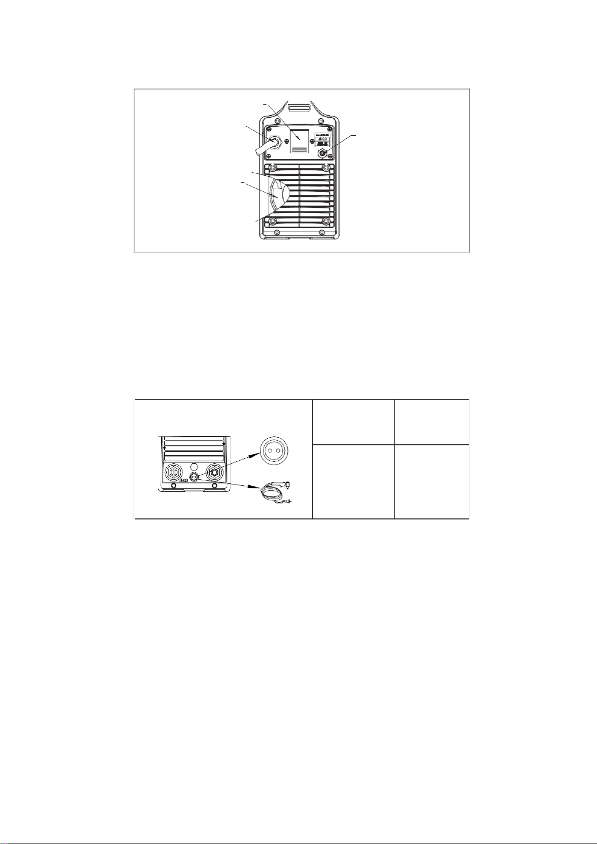
Rear panel
9
Fig. 4-3-2: Rear panel
1. Circuit breaker
Switch for single-phase AC220V±15% power. Turn on this switch (on the position: “ON”), then
the power on indicator lights up, and the fan runs.
2. Power supply cable
Three pin wires, the mixed-colored wire must be firmly grounded; the rest 2 wires connect to
1- phase AC 220V±15% 50/60Hz power supply.
3. Gas inlet
Connect with compress gas source by gas hose.
4. Fan
Cool down the heat components in the cutting machine.
4-4
Connections
Control socket
1 2
Socket Pin
Description
1, 2
Torch trigger
Table 4-4-1: Connections
Output socket
The output socket of this cutting machine is fast plug-in type.
1
2
ON
3
OFF
4

10
Gas hose
Air
compresser
Input
cable
CUT40i
25 30
20
35
15
40
CURRENT(A )
1-phase
Work piece
Ground
cable
Grounding
Cutting
torch
gas-electric
connector
Control cable
Torch
Fig. 4-4-1: Output socket
4-5
Installation and operation
Warning! An electric shock can be fatal. If the machine is plugged into the mains
electricity supply during installation, there is high risk of very serious injury and
damage. Do not use the functions described here until you have read and
completely understood “Safety Rules” in the beginning. Only carry out work on the
machine when
-
the mains switch is in turn-off position,
-
the machine is unplugged from the mains.
CUT40i cutting machine wire diagram as Fig. 4-5-1:
Fig. 4-5-1: Installation of CUT40i
Input power supply cable installation
Please note the size of fuse and circuit breaker in the table below are for reference only.
Fast plug
-
in type
11
E
L
N
E
GND
N L
GND/PE Earth
Ground
Yellow-Green mixed wire is used for
grounding! Not connected to zero wire!
Please connect according to picture or other
correct way. Please disconnect mains
power when connecting!
Model
CUT40i
Power supply
1- phase AC 220V±15%, 50/60Hz
Min. power capacity (KVA)
9
Input volt.
protection
(A)
Fuse
50
Circuit breaker
60
Min. cable size
(mm2)
Input cable
2.5
Output cable
16
Protective GND wire
2.5
Table 4-5-1: Input power supply cable installation
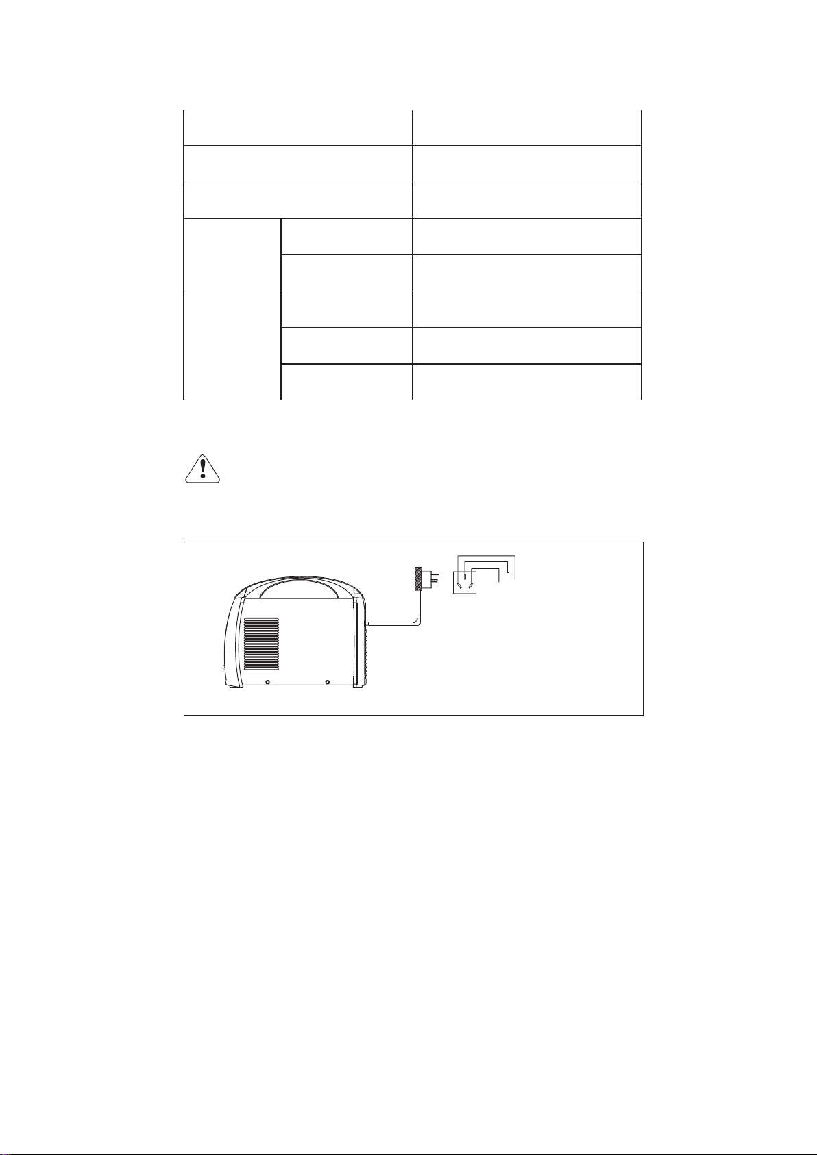
The connection between input cable and distribution box (Fig. 4-5-2)
Warning!
-
Never connection when equipment is power on!
-
The connection must be carried out by a qualified electrician!
-
Do not connect two units of power sources to the same circuit breaker!
-
Connected to the correct input voltage, circuit breaker, input cable as per the
specification on Table 4-5-1.
Fig. 4-5-2: Connection between input power supply cable and switch box

12
Power socket and using region
A: 2-plug flat type
B: 2-plug flat + GND
round hole type
C: 2-plug flat 8 type
D: 3-plug flat 8 type
E: 2-plug round (4.0mm) type
F: 2-plug round (4.0mm) type
G: 2-plug round + GND
round hole type
I: 3-pin flat type
K: 3-pin round type
M: Switzerland type
N: Italy type
O: Denmark type
Table 4-5-2: Power socket selection
Country
Type
Country
Type
Asian-Pacific region
Hong-Kong
I
Macau
E, G
Vietnam
A, B, E, G
Thailand
A, B
Malaysia
I
Singapore
I
Indonesia
E, G
India
I, K
Australia
C, D
New-Zealand
C, D
Japan
A, B
Korea
E, G

13
Country
Type
Country
Type
Middle East region
SaudiArabia
A, B, I
Iran
E
Dubai
G
Europe region
Italy
E, N
Austria
E, F, G
Poland
E, F, G
Hungary
F, G
Greece
E, F, G
Belgium
E, F, G
Netherlands
E, F, G
United Kingdom
I
France
E, F, G
Switzerland
E, M
Spain
E, F, G
German
E, F, G
Finland
E, F, G
Denmark
E, F, G, O
Russia
E, F, G
Turkey
E, F
America region
United States
A, B
Canada
A, B
Mexico
A, B
Columbia
A, B
Venezuela
A, B
Brazil
A, B, E
Peru
A, B, E
Argentina
C, D
Chile
E, N
Uruguay
E
Africa region
Rep. South Africa
K
Table 4-5-3: Using region selection
Cutting
Warning! Operating the equipment incorrectly can cause serious injury and damage.
Do not use the functions described here until you have read and completely
understood the following documents:
-
“Safety rules”
-
“Before commissioning”
Warning! Preparing when plug is on and power switch is in turn-on position may
cause danger. Switch it off and unplug it from the mains when preparing.
1. Plug the ground cable into output socket (+), and tighten it firmly;
2. Connect the other end of the ground cable to the work piece;
3. Plug the 2-pin plug of torch into the cutting machine control socket;
4. Plug gas-electric connector of torch to cutting machine gas-electric socket, and tighten it
firmly;

14
Note! When connect ground cable, power off cutting machine, align plug lug boss with socket
gap, insert and rotate in clockwise direction until fix well. Must ensure good connection
between plug and socket, otherwise high heat may burn plug and socket.
5. Air filter pressure-reducing valve is installed inside of cutting machine, connect its gas inlet
with gas outlet of air compressor;
Note! Max. working pressure of air compressor is 0.8Mpa, min. is 0.6 Mpa, gas flow rate ≥
250L/min.
6. Connect with single phase 220V power supply;
7. Turn on the power switch of the cutting machine, power on indicator lights up;
8. Open air valve of air compressor, gas flows;
9. Pull up gas adjustment knob of pressure-reducing valve to adjust pressure, press torch
trigger, rotate knob to adjust pressure to 3.5-5 bar, and press down the knob to lock the
adjusted value;
10. Adjust proper cutting current according to work piece thickness;
11. Contact torch nozzle with work piece arc starting point;
Note! Usually start cutting at edge of work piece, also can start cutting at any point of work
piece, at this time, should incline torch so as to blow off molten metal, and form original cut.
12. Press torch trigger to start arc;
On 2 step mode: press torch trigger-gas feeds-HF arc start-arc starts-start cutting-release
torch trigger-gas post flows-stop cutting;
13. Release torch trigger to stop cutting, and then remove torch after gas stops feeding;
14. Close air valve of compressor.
4-6
Technical data
Note! Please use the machine under the allowed power supply voltage range
marked in the nameplate. The technical data with the basic input voltage are listed as
the Table 4-6-1.
Model
CUT40i
Input volt/frequency
Single phase AC220V±15%/50/60HZ
Rated input capacity (KVA)
7
Rated input current (A)
32
Rated duty cycle (%)(40℃)
60
Output current range (A)
15~40
Output open circuit voltage (V)
285
Max. carbon steel cutting thickness (mm)
12
Optimal carbon steel cutting thickness (mm)
1~7
Weight (Kg)
9
Dimension (cm3)
39×16×30
Insulation class
F
Post-gas time (S)
30
Arc-starting type
Contact
Standard cutting torch
PT31
Table 4-6-1: Technical data

15
4-7
Main components list
Fig. 4-7-1: Inner structure
13
12
7
9
1
2
11
8
17
3
10
4
5
19
18
16
6
15
14

16
No.
Item
Stock no.
Remark
1
Knob
745003-00034
220V, 50Hz
2
Potentiometer
720031-00105
220V, 50Hz
3
Quick socket
740002-00079
220V, 50Hz
4
Socket copper core with gas hole
766001-01690
220V, 50Hz
5
Aviation socket
740001-00214
220V, 50Hz
6
Display board
220503-00126
220V, 50Hz
7
Circuit breaker
745011-00068
220V, 50Hz
8
Fan
746002-00025
220V, 50Hz
9
Power transformer
220179-00616
220V, 50Hz
10
Solenoid valve
752001-00037
220V, 50Hz
11
Pressure-reducing valve
766003-02164
220V, 50Hz
12
Rectifier bridge
735004-00005
220V, 50Hz
13
Fuse
745007-00045
220V, 50Hz
14
Aluminum electrolytic capacitor
722004-00105
220V, 50Hz
15
Output reactor
763004-00159
220V, 50Hz
16
IGBT single tube
735003-00011
220V, 50Hz
17
Main transformer
763002-00024
220V, 50Hz
18
Main control drive board
210580-00644
220V, 50Hz
19
Over voltage protection board
220900-00242
220V, 50Hz
Table 4-7-1: Main components list
Note: If no special remarks, the input voltage mentioned in above table is single phase.

17
5-
TROUBLE SHOOTING
Note! The following troubles and causes are uncertain. However, during the process
of normal using conditions, that might happen.
NO.
TROUBLE
CAUSES
REMEDY
1
Power on indicator
does not light up, fan
does not run, no
output when machine
switches on
1)
Power switch is
damaged
2)
No electricity on the
electricity grid
3)
Connect to 380V power
1)
Check power
switch, fan connection
between main control
board and display
board
2)
Check power supply
on the electricity grid
3)
Check
2
Power on indicator
lights up, but
protection on
indicator does not
light, and no output
1)
Output cable does not
connect well
2)
Bad connection of
joints, especially torch
trigger cable connection
3)
Display board is
damaged
1)
Check output cable
connection
2)
Check connection
3)
Check and repair
3
Protection on
indicator lights up
1)
Inner temperature is too
high
2)
Temperature relay is
broken
3)
Fan is locked-rotor, fan
cable is broken
4)
Gas shortage
1)
Let the machine
cool down
2)
Replace
3)
Check
4)
Check gas pressure
4
Circuit breaker on the
switchboard trips
while in cutting
1) The following devices
may be damaged: power
IGBT tube, output diode,
input rectifier bridge,
thermistor, electrolytic
capacitor
1) Check and replace
5
The cutting current is
unstable
1)
Potentiometer is broken
2)
Current sensor is
damaged
3)
Bad connection of joints
1)
Check and replace
2)
Check and replace
3)
Check and replace
6
Cutting current is not
adjustable
1) Current adjustment
potentiometer on front
panel is damaged
1) Check and replace

18
NO.
TROUBLE
CAUSES
REMEDY
7
No gas flows out
during cutting
1)
Solenoid valve is
damaged
2)
Gas flow is blocked
3)
The output air pressure
of air filter pressure-
reducing valve is too high
1)
Check and replace
2)
Check gas flow
3)
Regulate pressure
knob on the filter to
reduce air pressure
8
Too wide cut
1)
Slow cutting speed
2)
Nozzle is burn out
1)
Increase cutting
speed
2)
Replace
9
Non-vertical cut
1)
Nozzle is burn out
2)
Non-alignment of nozzle
to electrode
3)
Cutting torch is not
vertical to work piece
surface
1)
Replace
2)
Align the nozzle and
the electrode
3)
Adjust to vertical
position
Table 5-1: Trouble shooting
19
6
- CARE AND MAINTENANCE
Before open the machine
Warning! An electric shock can be fatal. Before doing any work on the machine:
-
Switch it off and unplug it from the mains
-
Put up a clearly legible and easy-to-understand warning sign to stop anybody
inadvertently switching it back on again
-
Discharge the capacity if necessary
-
Bolt in outer case also works for ground connection. Never use other bolt which
cannot work for ground connection
Maintenance of cutting machine
Please follow the instructions as below to ensure normal use of cutting machine
-
Conduct safety check at regular intervals (see “Safety rules”)
-
Dismantle machine side panels and clean machine inside with clean and low-pressure
compressed air by professional technician, not less than twice per year. Clean the
components at a certain distance only
-
If a lot of dust has accumulated, clean the cooling-air ducts
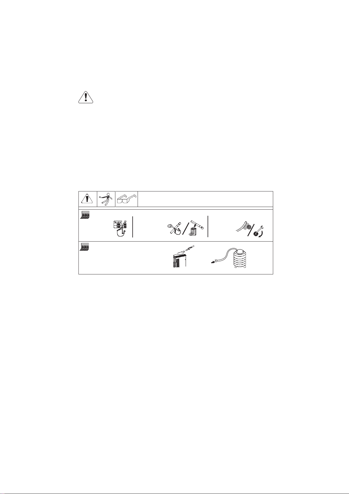
Daily maintenance
Disconnect main power before maintenance
3 months
Change
illegible
labe
Repair or
replace
broken
cable
Clean and
tighten
welding
terminal
6 months
Blow or suck inner part,
and clean every month
when working in
harsh environmental
condition
Fig. 6-1: Daily maintenance

20
(-)
Plasma
cutting
t orch
Work piece
Negative
t erminal
Cutting
m achine
R
Arc
m aintenance
cabl e
Electrode
S
Nozzle
Positive
term inal
Work
pie ce
7
- BASIC CUTTING TECHNIQUE
Note! This section being general welding technique guide is for reference only.
Specific functions of your machine please refer to previous chapters.
Air plasma cutting is a cutting method using plasma arc thermal energy. When cutting, use
plasma arc to melt work piece, blow molten metal by jet stream to form cut. Air plasma cutting
can cut almost all metal materials, especially for high alloy steel and nonferrous metal which
cannot be cut by flame cutting.Advantages are as follows: highly centralized arc energy, good
stability, strong cutting ability; high cutting speed (3~5 times of gas cutting); low cost; arrow,
burnished, clean and almost vertical cutting edge; less work piece deformation.
Fig. 7-1: Cutting process
1.Plasma arc type
According to power source connecting method, there are two kinds: transferred arc and non-
transferred arc.
(1)
Transferred type
Power source negative output terminal is connected with electrode; positive terminal is
connected with work piece. Plasma arc is generated between electrode and work piece. First,
it needs to ignite plasma flame flow between electrode and nozzle, and plasma airflow makes
plasma flame flow contact with work piece to form plasma arc. Plasma arc formed by this
transferred method is called transferred arc. Transferred arc can reduce nozzle burning
caused by arc starting or liquid metal spatter.
Fig. 7-2: Transferred type
This manual suits for next models
1
Table of contents


