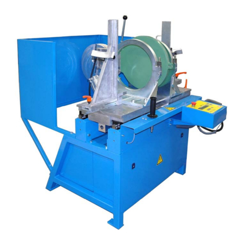
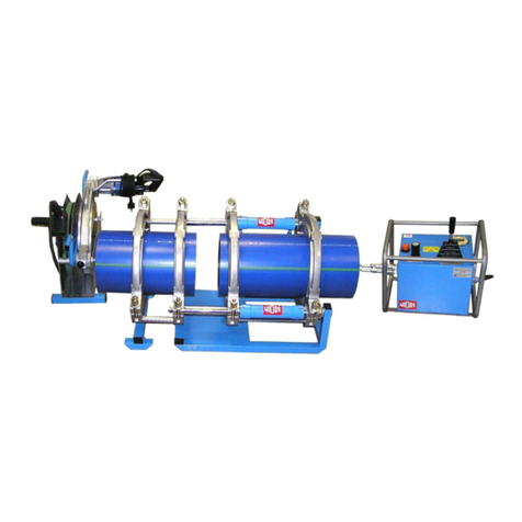
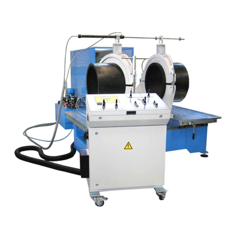
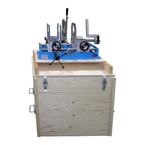
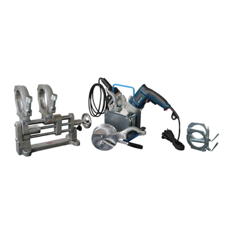
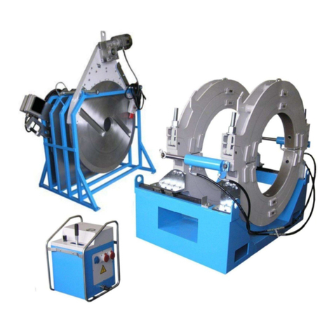
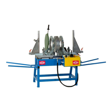
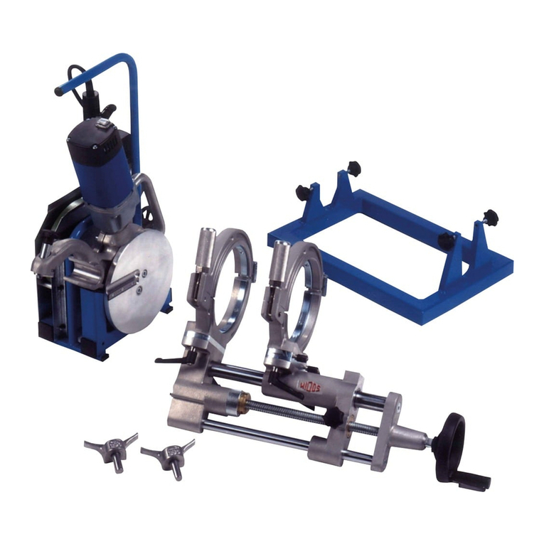
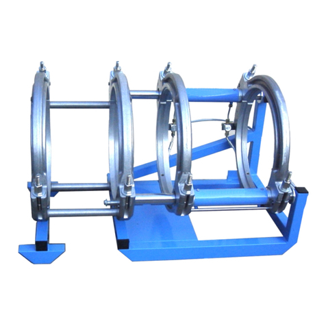
widos 4000 WM User manual

Kunststoffschweißtechnik
WIDOS Einsteinstr. 5 Phone +49 (0) 71 52 99 39 - 0
W. Dommer Söhne GmbH D-71254 Ditzingen-Heimerdingen Fax +49 (0) 71 52 99 39 - 40
Website: www.widos.de Email: info@widos.de
Headquarters: D-71254 Ditzingen-Heimerdingen Country court Stuttgart HRB 200973 Managing director: Jürgen Dommer
Working instructions
Translation
Heating element butt welding machine
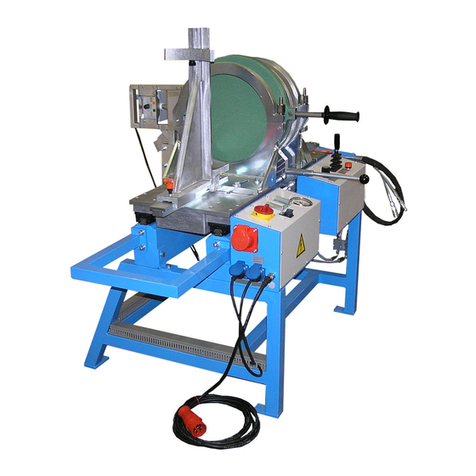
WIDOS 4000 WM
15°-clamping tool, additional cylinder and T-90° / T-60° / T-45° (optional)
Keep for further use!

Kunststoffschweißtechnik
Product identification
20.08.2014 Working instructions WIDOS 4000 WM Page 2 of 68
Model: Workshop machine
Type: WIDOS 4000 WM
Serial number, year of construction: see type label
Customer entries
Inventory-No.:
Location:
Order of spare parts and sales services
Address of manufacturer WIDOS
Wilhelm Dommer Söhne GmbH
Einsteinstrasse 5
D-71254 Ditzingen-Heimerdingen
Phone: +49 (0) 71 52 / 99 39 - 0
Fax: +49 (0) 71 52 / 99 39 - 40
Address of the subsidiary companies:
WIDOS
WIDOS GmbH Wilhelm Dommer Söhne AG
An der Wiesenmühle 15 St. Gallerstr. 93
D-09224 Grüna / Sachsen CH-9201 Gossau
Phone: ++49 371 / 8 15 73 - 0 Phone: +41 (0) 79 432 57 37
Fax: ++49 371 / 8 15 73 - 20

Kunststoffschweißtechnik
Introduction
20.08.2014 Working instructions WIDOS 4000 WM Page 3 of 68
Purpose of the document
These working instructions give you information about all important questions which refer to
the construction and the safe working of your machine.
Just as we are, you are obliged to engage in this working instruction, as well.
Not only to run your machine economically but also to avoid damages and injuries.
Should questions arise, contact our advisers in the factory or in our subsidiary companies.
We will help you with pleasure.
According to our interest to continuously improve our products and working instructions, we
kindly ask you to inform us about problems and defects which occur in exercise.
Thank you.
Structure of the working instructions
This manual is arranged in chapters, which belong to the different using phases of the
machine.
Therefore the searched information can be easily found.
8/20/2014 WIDOS
W. Dommer Söhne GmbH
Einsteinstraße 5
D-71254 Ditzingen-Heimerdingen
All rights reserved
Reprinting only allowed with permission of the corporation.
Any changes are subject to technical innovations.

Kunststoffschweißtechnik
WIDOS Einsteinstr. 5 Phone +49 (0) 71 52 99 39 - 0
W. Dommer Söhne GmbH D-71254 Ditzingen-Heimerdingen Fax +49 (0) 71 52 99 39 - 40
Website: www.widos.de Email: info@widos.de
20.08.2014 Working instructions WIDOS 4000 WM Page 4 of 68

Kunststoffschweißtechnik
Contents
20.08.2014 Working instructions WIDOS 4000 WM Page 5 of 68
1. DESCRIPTION OF PRODUCT........................................................................................ 7
1.1. Usage and purpose-oriented use........................................................................................7
1.2. Safety measures ...................................................................................................................7
1.3. Conformity.............................................................................................................................7
1.4. Marking of product ...............................................................................................................8
1.4.1. Technical data ................................................................................................................8
1.4.1.1. WIDOS 4000 WM general data ................................................................................8
1.4.1.2. Basic unit ...................................................................................................................8
1.4.1.3. Heating element.........................................................................................................9
1.4.1.4. Planer.........................................................................................................................9
1.4.1.5. Hydraulic aggregate...................................................................................................9
1.5. Wear Parts .............................................................................................................................9
1.6. Tools and Accessories.......................................................................................................10
1.7. Equipments (optional)........................................................................................................10
2. SAFETY RULES............................................................................................................ 13
2.1. Explanation of the different symbols................................................................................13
2.2. Obligations of the owner....................................................................................................14
2.3. Obligations of the worker ..................................................................................................14
2.4. Measure of organization ....................................................................................................14
2.5. Information about safety precautions ..............................................................................14
2.6. Instructions for the staff ....................................................................................................14
2.7. Dangers while handling the machine ...............................................................................15
2.8. Dangers by electrical energy.............................................................................................15
2.9. Dangers by hydraulic .........................................................................................................15
2.10. Specific dangers.................................................................................................................15
2.10.1. Danger of combustion by heating element and welding area......................................15
2.10.2. Danger of crushing between machine tables / clamping tools ....................................16
2.10.3. Danger of cutting and drawing-in of clothes by the planer...........................................16
2.10.4. Danger of stumbling over electric wire.........................................................................16
2.10.5. Risk of injury by noises ................................................................................................16
2.11. Structural modifications on the machine.........................................................................17
2.12. Warranty and Liability ........................................................................................................17
3. FUNCTIONAL DESCRIPTION ...................................................................................... 19
4. OPERATING AND INDICATING ELEMENTS .............................................................. 21
4.1. Machine overview ...............................................................................................................21
4.2. Horizontal adjustment (mismatch compensation)..........................................................22
4.3. Elements at the heating element.......................................................................................23
4.4. Main switch..........................................................................................................................23
4.5. Elements at the planer........................................................................................................24
4.6. Switch cabinet.....................................................................................................................25
4.7. Clamping tools with 15° .....................................................................................................25
4.7.1. How to install the reducer inserts (optional).................................................................26
Kunststoffschweißtechnik
Contents
20.08.2014 Working instructions WIDOS 4000 WM Page 6 of 68
4.7.2. How to mount the clamping tool onto the table for angles 0°/30°/45°......................... 26
4.7.3. How to mount the clamping tool onto the table for other angles ................................. 27
4.7.4. Assembly: Clamping tools for straight pipes ............................................................... 28
4.7.5. Assembly: Clamping tools for angle 30°...................................................................... 29
4.7.6. Assembly: Clamping tools for angle 45°...................................................................... 30
4.8. How to work with the optional additional cylinder......................................................... 31
4.9. Stub end holder (optional).................................................................................................32
4.10. Plane girder to plane at one side only (optional)............................................................32
5. STARTING AND OPERATING ......................................................................................33
5.1. Safety indications...............................................................................................................33
5.2. Starting................................................................................................................................33
5.3. Welding process.................................................................................................................34
5.3.1. How to clamp the pipes ............................................................................................... 35
5.3.2. Drag pressure measurement....................................................................................... 35
5.3.3. How to plane the pipes ................................................................................................ 35
5.3.4. Mismatch compensation.............................................................................................. 36
5.3.5. Adjusting ...................................................................................................................... 36
5.3.6. Heating-up ................................................................................................................... 37
5.3.7. Change-over ................................................................................................................ 37
5.3.8. Joining .........................................................................................................................37
5.4. How to weld angles............................................................................................................38
5.5. How to weld segmented bends ........................................................................................38
6. WELDING TABLES .......................................................................................................39
6.1. Formulas for the welding of pipes with different diameters .........................................39
7. WELDING T-PIECES WITH 90° AND 45° .....................................................................46
7.1. Preparing pipes for T–pieces............................................................................................ 46
7.2. Assembly: Clamping tools for T–piece 90° .....................................................................48
7.3. Assembly: Clamping tools for T – piece 45° ................................................................... 49
8. EQUIPMENT CARE / MAINTENANCE / REPAIR .........................................................52
8.1. Transport.............................................................................................................................52
8.2. Maintenance, inspection and repair................................................................................. 52
8.3. Clamping elements ............................................................................................................ 53
8.4. Planer...................................................................................................................................53
8.5. How to check the oil level / how to refill.......................................................................... 53
8.5.1. Used hydraulic oil ........................................................................................................ 54
8.6. Protect machine parts against corrosion........................................................................54
8.7. Disposal...............................................................................................................................54
9. WIRING DIAGRAMS......................................................................................................56
10. DECLARATION OF CONFORMITY...............................................................................68

Kunststoffschweißtechnik
WIDOS Einsteinstr. 5 Phone +49 (0) 71 52 99 39 - 0
W. Dommer Söhne GmbH D-71254 Ditzingen-Heimerdingen Fax +49 (0) 71 52 99 39 - 40
Website: www.widos.de Email: info@widos.de
20.08.2014 Working instructions WIDOS 4000 WM Page 7 of 68
1. Description of product
This chapter gives important basic information about the product and its prescribed use.
All technical details of the machine are put together as a general arrangement.
1.1. Usage and purpose-oriented use
The WIDOS 4000 WM is a workshop machine for heating element butt welding of pipes and
fittings Ø = 63 – 315 mm.
(Standard-: 63 / 75 / 90 / 110 / 125 / 140 / 160 / 180 / 200 / 225 / 250 / 280 / 315 mm).
The machine is screwed tightly on a steel pipes frame in the right working height and has two
movable machine parts (floatingly supported) with two clamping tools.
For the balance of diameter tolerances the right table half is diagonally movable to the work
direction.
For the production of segment bends both clamping tools can be moved.
The machine can weld T-pieces with (optional) T – clamping tools 45° / 60° / 90°; with OD =
315 mm.
By means of an (optional) additional cylinder huge diameters with high nominal pressure
ratings may also be clamped and welded.
All use going beyond is not prescribed.
The manufacturer is not responsible for damages caused by misuse.
The risk is held only by the user.
Also part of the appropriate usage are
following all indications of the working instructions and
performing the inspection and maintenance works.
1.2. Safety measures
In case of wrong use, wrong operation or wrong maintenance, the machine itself or products
standing nearby may be damaged or destroyed.
Persons who stay in the danger area may suffer injuries.
Therefore the working instructions on hand are to be red thoroughly and the corresponding
safety instructions are to be observed by all means.
1.3. Conformity
The machine corresponds in its construction to the valid recommendations of the European
Community as well as to the according European standard specifications.
The development, manufacturing and mounting of the machine were made very carefully.

Kunststoffschweißtechnik
Description of product Chapter 1
20.08.2014 Working instructions WIDOS 4000 WM Page 8 of 68
1.4. Marking of product
The product is marked by type-label.
They contain the machine type, the serial number and the year of construction.
1.4.1. Technical data
All important technical data of the single components are listed.
They permit a rapid information about output and structure.
1.4.1.1. WIDOS 4000 WM general data
Material: PP; PE, PVDF
Size of the pipe: OD = 63 – 315 mm
Power: 400 V (± 10%)
Power: 5,1 kVA
Frequency: 50 Hz (± 10%)
Connection: CEE 16A
Power section: 1,5 mm²
Weight: appr. 590 kg (without package and accessories)
Dimensions (W x H x D) 1200 (1900 with T-45°) x 1185 x 2000 mm
Emissions - Noise exceeding 80 dB (A) may occur; during planing
it is obligatory to wear ear protection!
- In case of use of the prescribed plastic materials and
if the work is performed inside the temperature range
up to 260 °C no toxic fumes will be generated.
Environmental conditions in the
welding area:
- Be aware of cleanliness (no dust at the welding point)
- If secured by an appropriate measurement that
allowed conditions for welding are indicated, it is
possible to work in any outside temperature condition
as far as the welder is not constrained in its manual
skill.
- prevent from moisture influence
- avoid strong sun rays radiations
- prevent from strong wind
- Be careful when moving in and out heating element
and planer
1.4.1.2. Basic unit
Frame material: Construction steel
Cylinder-/ piston rod-: 32 / 18 mm
max. force (F = P*A): 54,97 N/bar
10,99 kN (at 200 bar)
Cylinder-Ø / piston rod-Ø
additional cylinder (optional):
22 / 18 mm
max. force with additional cylinder
(optional) (F = P*A):
67,53 N/bar
13,51 kN (at 200 bar)

Kunststoffschweißtechnik
Description of product Chapter 1
20.08.2014 Working instructions WIDOS 4000 WM Page 9 of 68
1.4.1.3. Heating element
Power: 5,4 kW
Voltage: 400 V (10 %)
Amperage: 13,5 A (10 %)
Frequency: 50 Hz
Surface: anti-stick coated
1.4.1.4. Planer
Motor: Monophase-alternate current universal motor
Power: 1,4 kW
Voltage: 230 V (10 %)
Amperage: 4,9 A
Frequency: 50 Hz (10 %)
Speed planer disc: 50 - 70 rpm
1.4.1.5. Hydraulic aggregate
Power: 0,75 kW
Voltage: 400 V (10 %)
Amperage: 1,69 A
Frequency: 50 Hz
Hydraulic oil tank: appr. 1 L
Type of protection IP 55
Electric motor and pump:
Engine revolution: 3500 (U/min)
max. working pressure of pump: appr. 210 bar
Working pressure: 200 bar
1.5. Wear Parts
Pieces /
machine: Name: Order no.:
1 Heating element on request
1 Heating plate in exchange HPT4002E
1 Temperature probe PT 1000 H09082
4 Blade 120 mm MES120
4 Blade 170 mm MES170
40 Flat-head screw M 3x8 (DIN 965) with Torx-drive 0965C008X
1 l Hydraulic oil HLDP35

Kunststoffschweißtechnik
Description of product Chapter 1
20.08.2014 Working instructions WIDOS 4000 WM Page 10 of 68
1.6. Tools and Accessories
The following tools and accessories is part of the original delivery:
Pieces: Name:
1 Tool bag for 10 parts
1 Screwdriver TX10
1 Key for switch cupboard
Attention! Hand over the key to authorized personnel only.
1 Socket spanner size 27
1 each Combination spanner size 13 / 19
1 each Allan key tilted size 6 / 8
1.7. Equipments (optional)
Pieces Denomination
1 Stub end holder inclusive clamping claws
1 Additional cylinder
1 Plane girder to plane at one side only
Reduction inserts for clamping tool with 15°
4
4
Reduction insert OD 63 in OD 75 mm
Flat-head screw M 10 x 140 DIN 7991
4
4
Reduction insert OD 75 in OD 90 mm
Flat-head screw M 10 x 140 DIN 7991
4
4
Reduction insert OD 90 in OD 110 mm
Flat-head screw M 10 x 130 DIN 7991
4
4
Reduction insert OD 110 in OD 125 mm
Flat-head screw M 10 x 120 DIN 7991
4
4
Reduction insert OD 125 in OD 140 mm
Flat-head screw M 10 x 110 DIN 7991
4
4
Reduction insert OD 140 in OD 160 mm
Flat-head screw M 10 x 100 DIN 7991
4
4
Reduction insert OD 160 in OD 180 mm
Flat-head screw M 10 x 90 DIN 7991
4
4
Reduction insert OD 180 in OD 200 mm
Flat-head screw M 10 x 80 DIN 7991
4
4
Reduction insert OD 200 in OD 225 mm
Flat-head screw M 10 x 70 DIN 7991
4
4
Reduction insert OD 225 in OD 250 mm
Flat-head screw M 10 x 60 DIN 7991
4
4
Reduction insert OD 250 in OD 280 mm
Flat-head screw M 10 x 45 DIN 7991
4
4
Reduction insert OD 280 in OD 315 mm
Flat-head screw M 10 x 25 DIN 7991

Kunststoffschweißtechnik
Description of product Chapter 1
20.08.2014 Working instructions WIDOS 4000 WM Page 11 of 68
Pieces Denomination
1 set T-90°-clamping tool
1 set
6
T-reduction insert DA 90 in DA 110 mm
Flat-head screw M 10 x 130 DIN 7991
1 set
6
T- reduction insert DA 110 in DA 125 mm
Flat-head screw M 10 x 120 DIN 7991
1 set
6
T- reduction insert DA 125 in DA 140 mm
Flat-head screw M 10 x 120 DIN 7991
1 set
6
T- reduction insert DA 140 in DA 160 mm
Flat-head screw M 10 x 120 DIN 7991
1 set
6
T- reduction insert DA 160 in DA 180 mm
Flat-head screw M 10 x 90 DIN 7991
1 set
6
T- reduction insert DA 180 in DA 200 mm
Flat-head screw M 10 x 90 DIN 7991
1 set
6
T- reduction insert DA 200 in DA 225 mm
Flat-head screw M 10 x 90 DIN 7991
1 set
12
T- reduction insert DA 225 in DA 250 mm
Flat-head screw M 10 x 60 DIN 7991
1 set
12
T- reduction insert DA 250 in DA 280 mm
Flat-head screw M 10 x 45 DIN 7991
1 set
12
T- reduction insert OD 280 in OD 315 mm
Flat-head screw M 10 x 45 DIN 7991
2 T-45°-clamping tool
2
4
T- reduction insert OD 90 in OD 110 mm
Flat-head screw M 10 x 130 DIN 7991
2
4
T- reduction insert OD 110 in OD 125 mm
Flat-head screw M 10 x 120 DIN 7991
2
4
T- reduction insert OD 125 in OD 140 mm
Flat-head screw M 10 x 120 DIN 7991
2
4
T- reduction insert OD 140 in OD 160 mm
Flat-head screw M 10 x 120 DIN 7991
2
4
T- reduction insert OD 160 in OD 180 mm
Flat-head screw M 10 x 90 DIN 7991
2
4
T- reduction insert OD 180 in OD 200 mm
Flat-head screw M 10 x 90 DIN 7991
2
4
T- reduction insert OD 200 in OD 225 mm
Flat-head screw M 10 x 90 DIN 7991
2
8
T- reduction insert OD 225 in OD 250 mm
Flat-head screw M 10 x 60 DIN 7991
2
8
T- reduction insert OD 250 in OD 280 mm
Flat-head screw M 10 x 45 DIN 7991
2
8
T- reduction insert OD 280 in OD 315 mm
Flat-head screw M 10 x 45 DIN 7991

Kunststoffschweißtechnik
WIDOS Einsteinstr. 5 Phone +49 (0) 71 52 99 39 - 0
W. Dommer Söhne GmbH D-71254 Ditzingen-Heimerdingen Fax +49 (0) 71 52 99 39 - 40
Website: www.widos.de Email: info@widos.de
20.08.2014 Working instructions WIDOS 4000 WM Page 12 of 68

Kunststoffschweißtechnik
WIDOS Einsteinstr. 5 Phone +49 (0) 71 52 99 39 - 0
W. Dommer Söhne GmbH D-71254 Ditzingen-Heimerdingen Fax +49 (0) 71 52 99 39 - 40
Website: www.widos.de Email: info@widos.de
20.08.2014 Working instructions WIDOS 4000 WM Page 13 of 68
2. Safety rules
The basic condition for the safety conscious handling and the fault free operation of this
machine is the knowledge of the basic safety advises and rules.
These working instructions contain the most important indications for running the machine
according to the safety regulations.
The safety indications need to be followed by all persons working on the machine.
2.1. Explanation of the different symbols
In the working instructions the following designations and signs are used for potential dangers:
This symbol means a possibly danger for the life and the health of persons.
The disrespect of these indications may have heavy consequences for the
health.
This symbol means a possible dangerous situation.
The disrespect of these indications may cause slight injuries or damages on
goods.
This symbol means a possible dangerous situation due to hot surfaces.
The disrespect of these indications may conduct to heavy burns, respectively
to self-ignition or even fire.
This symbol means a possible dangerous situation by moving parts of the
machine
The disrespect of these indications may cause heavy crushing of parts of the
body resp. damages of parts of the machine.
This symbol means a possible risk of injury by noises exceeding 80 dB (A).
Ear protection is obligatory
This symbol gives important indications for the proper use of the machine.
The disrespect of these indications may conduct to malfunctions and damages
on the machine or on goods in the surrounding.
Under this symbol you get user tips and particularly useful information.
It is a help for using all the functions on your machine in an optimal way and
helps you to make the job easier.
The accident prevention measures are valid (UVV).

Kunststoffschweißtechnik
Safety rules Chapter 2
20.08.2014 Working instructions WIDOS 4000 WM Page 14 of 68
2.2. Obligations of the owner
The owner is obliged only to let persons work at the machine who
know about basic safety and accident prevention rules and are instructed in the handling of
the machine, as well as who
the workers also must have read and understood the safety chapter of this manual and
certify this by their signature
The safety-conscious working of the staff has to be checked in regular intervals.
2.3. Obligations of the worker
All persons who are to work at the machine are obliged:
to follow the basic safety and accident protection rules,
to have read and understood the safety chapter and the warnings in this manual and to
confirm by their signature that they have well understood them,
to inform themselves about the functions of the machine before using it, before working.
2.4. Measure of organization
All equipment required for personal safety is to be provided by the owner.
All available safety equipment is to be inspected regularly.
2.5. Information about safety precautions
The working instructions have to be permanently kept at the place of use of the machine.
They are to be at the operator's disposal at any time and without much effort.
In addition to the manual, the common valid and the local accident protection rules and
regulations for the environmental protection must be available and followed.
All safety and danger indications on the machine have to be in a clear readable condition.
Every time the machine changes hands or is being rent by a third person, the working
instructions are to be sent along with and their importance is to be emphasized.
2.6. Instructions for the staff
Only skilled and trained persons are allowed to work at the machine.
It must be clearly defined who is responsible for transport, mounting and dismounting, and
starting the operation.
A person who is being trained may only work at the machine under supervision of an
experienced person.

Kunststoffschweißtechnik
Safety rules Chapter 2
20.08.2014 Working instructions WIDOS 4000 WM Page 15 of 68
2.7. Dangers while handling the machine
The machine WIDOS 4000 WM is constructed according to the latest technical standard and
the acknowledged technical safety rules.
However, dangers for the operator or other persons standing nearby may occur. Also material
damages are possible.
The machine may only be used
according to the purpose-oriented use
in safety technical impeccable status
Disturbances which may affect the safety of the machine must be cleared immediately.
2.8. Dangers by electrical energy
Only skilled persons are allowed to work at electrical appliances.
The electrical equipment of the machine has to be checked regularly. Loose
connections and damaged cables have to be replaced immediately.
If work is to be done on the parts carrying voltage, a second person has to be consulted
who disconnects the current supply if necessary.
Protect the heating element and planer from rain and dropping water.
2.9. Dangers by hydraulic
System sections which have to be opened in case of repair works have to be
depressurized before starting to repair.
There is a danger of hurting your eyes because of a sudden squirting hydraulic
oil. The hydraulic oil can be hot!
Damaged hydraulic or pneumatic hoses have to be immediately replaced.
Before starting to work make a visual examination of the hydraulic lines.
The hydraulic oil is brackish!
The hydraulic oil is to be handled and disposed of in appropriate manner.
2.10. Specific dangers
2.10.1. Danger of combustion by heating element and welding area
You can burn yourself, inflammable materials can ignite.
The heating element temperature is heated up to more than 200° C!
Make sure that no one can touch the heated heating element.
Do not touch the surfaces of the heating element.
Do not leave the machine with heated heating element unsupervised.
Take enough safety distance to inflammable materials.
Do wear safety gloves.

Kunststoffschweißtechnik
Safety rules Chapter 2
20.08.2014 Working instructions WIDOS 4000 WM Page 16 of 68
2.10.2. Danger of crushing between machine tables / clamping tools
Heavy injuries can result from crushing:
upon closing the clamping tools
upon moving of planer and heating element
upon closing the clamping tools
upon closing the tables
Do not touch in-between clamped pipe ends.
Do not touch the guide rails for the tables, planer and heating element while moving the
machine.
Do not hinder the machine tables while moving.
Only close the clamping tools if no part of the body is between clamping tool and pipe resp.
between upper and lower part.
2.10.3. Danger of cutting and drawing-in of clothes by the planer
You can carry away cut injuries up to fractures!
Do wear formfitting clothes.
Do not wear any rings or jewelry during work.
If necessary wear a snood-type cap.
Make sure that nobody reaches into the driving area of the planer resp. that no
foreign object is within the driving area.
Only activate the planer discs if the planer is driven in and locked, respectively
if nobody touches the planer discs.
Always lock the planer prior to planing.
2.10.4. Danger of stumbling over electric wire
Pay attention that nobody has to step over the lines.
Favorably pass the line in order that the danger is minimized. Do not squeeze
and kink the lines or anything likewise.
2.10.5. Risk of injury by noises
Noises exceeding 80 dB (A) may occur; during planing it is obligatory to wear ear
protection!

Kunststoffschweißtechnik
Safety rules Chapter 2
20.08.2014 Working instructions WIDOS 4000 WM Page 17 of 68
2.11. Structural modifications on the machine
No modifications, extensions or reconstructions may be made on the machine without
permission of the manufacturer. In case of disrespect the warranty or liability will expire.
Machine parts which are not in a perfect condition are to be immediately replaced.
Only use original WIDOS spare and wear parts.
In case of purchase orders please always indicate the machine number!
2.12. Warranty and Liability
Our „General Sales and Delivery Conditions“ are principally valid.
They are at the owner's disposal at the latest when signing the contract.
Warranty and liability demands referring to damages of persons or objects are suspended if
they are caused by one or several of the following reasons:
not using the machine according to the prescriptions
improper transport, building-up, starting and operating the machine and maintenance
operating the machine with defective or improperly installed security measures
ignoring the information given in this manual
structural changes at the machine without permission
unsatisfactory checking of machine parts which are worn out
repairs performed in an inexpert way
catastrophes by external influence and Acts of God.

Kunststoffschweißtechnik
WIDOS Einsteinstr. 5 Phone +49 (0) 71 52 99 39 - 0
W. Dommer Söhne GmbH D-71254 Ditzingen-Heimerdingen Fax +49 (0) 71 52 99 39 - 40
Website: www.widos.de Email: info@widos.de
20.08.2014 Working instructions WIDOS 4000 WM Page 18 of 68

Kunststoffschweißtechnik
WIDOS Einsteinstr. 5 Phone +49 (0) 71 52 99 39 - 0
W. Dommer Söhne GmbH D-71254 Ditzingen-Heimerdingen Fax +49 (0) 71 52 99 39 - 40
Website: www.widos.de Email: info@widos.de
20.08.2014 Working instructions WIDOS 4000 WM Page 19 of 68
3. Functional description
Basically the international and national process guidelines are to be
followed!
First the clamping tools are fixed onto the machine.
For welding angles and bows the clamping tools might be displaced on both sides.
The plastic pipes are clamped by means of the clamping tools.
After this the front sides of the pipes are planed parallel and the misalignment of the pipes is
checked.
Then the heating element is driven inside and the pipes are pressed onto the heating element
under the defined pressure (this process is called: „adjustment time“).
After reaching the prescribed bead height the pressure is being reduced and this is the start of
the heating time.
The function of this time is to bring the pipe ends onto the welding temperature.
After completion of the heating time the machine is opened the heating element quickly driven
out and the pipes are again driven together hydraulically.
The time gap from driving out the heating element to the joining of the pipes is called change
over time.
They are put together with the prescribed welding pressure and then cool down under
pressure (cooling time).
The welding connection can now be unclamped: the welding process is completed.
Welded pipe with inside
and outside bead.
Heating element heats
the pipes up to welding
temperature.

Kunststoffschweißtechnik
WIDOS Einsteinstr. 5 Phone +49 (0) 71 52 99 39 - 0
W. Dommer Söhne GmbH D-71254 Ditzingen-Heimerdingen Fax +49 (0) 71 52 99 39 - 40
Website: www.widos.de Email: info@widos.de
20.08.2014 Working instructions WIDOS 4000 WM Page 20 of 68
Table of contents
Other widos Welding System manuals

widos
widos 7000 WM User manual

widos
widos 16000 mobile User manual

widos
widos MINIPLAST 2 / T-Piece User manual

widos
widos ESI 4000 User manual

widos
widos 4002 S WI CNC User manual

widos
widos WELD IT 315 Steel User manual

widos
widos 4400 User manual

widos
widos 2500 / OD 315 User manual

widos
widos 20000 User manual

widos
widos 6100 CNC 3.0 User manual

widos
widos PSM 15 User manual

widos
widos 4001 User manual

widos
widos 6113 mobile User manual

widos
widos 3511 User manual

widos
widos ASM 160 User manual

widos
widos 4900 CNC 3.0 User manual

widos
widos HRG 14 User manual

widos
widos 5100 User manual

widos
widos 6113 mobile User manual

widos
widos 4002 S WI CNC User manual