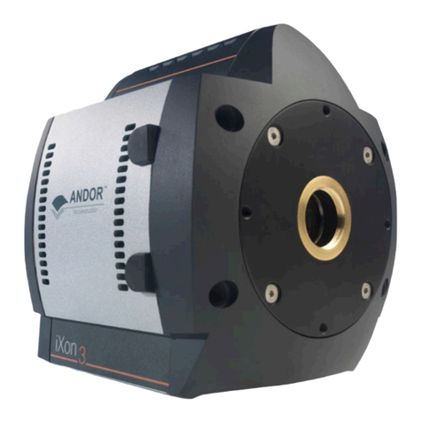
Andor Technology iXon Ultra 897 User manual

Version 1A
AUSER’S GUIDE TO ANDOR
ELECTRON MULTIPLYING CCD

Version 1A
AUSER’S GUIDE TO
ANDOR
ELECTRON MULTIPLYING CCD
©Andor Technology Ltd 2003

CONTENTS

CONTENTS
ABOUT THE ANDOR iXon CCD Section 1
Introduction to the Andor iXon CCD 1. 1
Technical Support 1. 2
INSTALLATION Section 2
Safety Precautions 2. 1
The iXon CCD System 2. 2
Installing the System 2. 3
Using the iXon CCD 2.4
File Information 2.5
Hot Keys 2.6
INSIDE THE iXon CCD Section 3
Electron Multiplying CCDs 3. 1
EMCCD Gain 3.2
WORKING WITH THE SOFTWARE Section 4
Working with Data 4.1
Getting Help 4.2
Handling Files 4.3
Data Acquisition 4.4
Setting the Acquisition 4.5
Choosing the Data Type 4.6
Displaying Data 4.7
Region of Interest 4.8
Using the Command Line 4.9
Entering Hardware Details 4.10
Shutter Control 4.11
Setting the Temperature 4.12
Organizing Your Windows 4.13
Using The Remote Control 4.14

CONTENTS
WORKING WITH PROGRAMS Section 5
Introduction 5. 1
Editing Programs 5. 2
Running Programs
5. 3
THIRD PARTY SOFWARE Section 6
Soft Imaging System 6. 1
Other S/W supported 6. 2
TUTORIALS Section 7
Tutorial 1 7. 1
Tutorial 2 7. 2
Tutorial 3 7. 3
APPENDICES Section 8
The Controller Card 8.1
Windows Glossary 8.2
Imaging Glossary 8.3
Terms and Conditions
8.4
INDEX Section 9

ABOUT THE ANDOR iXON CCD
Section 1
Introduction 1.1
Technical Support 1.2

INTRODUCTION
….
….
Congratulations on the purchase of your new Andor iXon camera.
You are now in possession of revolutionary new EMCCD detector, designed for
the most challenging low-light imaging applications.
Its unique features and design are discussed in more detail within this
User Guide.
This guide is designed as a road map for the iXon camera, and contains information
and advice to ensure you get the optimum performance from your new system.
As well as general advice on installation, handling electronics, and some background
to the unique EMCCD technology, the manual provides instructions on operating the
iXon software.
You can also make use of the Online Help for advice and instructions on getting the
best out of your iXon camera.
Towards the back of the manual there are a number of carefully prepared Tutorials
that will allow you to quickly demonstrate the unique capabilities of this
revolutionary detector.
Please feel free to contact Andor Technology directly, or your local representative or
supplier, if you have any questions regarding your iXon system.
Andor Technology Ltd
INTRODUCTION
Page 8 Section 1 . 1
In the software, all the controls you need for an operation are grouped and sequenced
appropriately in on-screen windows. As far as possible, the descriptions in this
User’s Guide are laid out in sections that mirror the Windows Interface.
The following type-styles are used in the right-hand margin of the User’s Guide to
pick out key features of the menus:-
Using The
Manual
•Menu
•Menu Option
These styles are reflected in the format of the main texts. In addition, windows and
dialog boxes are identified as:
•Active Window / Dialog Box
•Dialog Box - functional area
•Dialog Box - option, parameter, etc
•CCD Sensor - other significant features

TECHNICAL SUPPORT
Section 1 . 2
If you have any questions regarding the use of this equipment, please contact the
representative from whom your system was purchased, or:
9Millennium Way, Springvale Business Park
Belfast BT12 7AL, Northern Ireland
Tel. 44 (0) 28 90 23 7126 Fax. 44 (0) 28 90 31 0792
UK
435 Buckland Road, Rosewood Building,
South Windsor, CT 06074, USA
Tel. (860) 648-1085 Fax. (860) 648-1088
USA
503 Ichibancho Central Building
22-1 Ichiban-cho, Chiyoda-ku
Tokyo 102-0082, Japan
Tel. 81-3-3511 0659 Fax. 81-3-3511 0659
Japan

INSTALLATION
Section 2...
Safety Precautions 2. 1
The iXon CCD System 2. 2
Installing the System 2. 3
Using the iXon CCD 2.4
File Information 2.5
Hot Keys 2.6

INSTALLATION
…

SAFETY PRECAUTIONS
Page 12 Section 2 . 1
Working with Electronics
The computer equipment that is to be used to operate the iXon CCD Detector
should be fitted with appropriate surge/EMI/RFI protection on all power lines.
Dedicated power lines or line isolation may be required for some extremely noisy
sites.
Appropriate static control procedures should be used during the installation of the
system. Attention should be given to grounding. All cables should be fastened
securely into place in order to provide a reliable connection and to prevent accidental
disconnection. The power supply to the computer system should be switched off
when changing connections between the computer and the Detector Head.The
computer manufacturer's safety precautions should be followed when installing the
Interface Card into the computer.
The circuits used in the detector head and the interface card are extremely sensitive
to static electricity and radiated electromagnetic fields, and therefore they should not
be used, or stored, close to EMI/RFI generators, electrostatic field generators,
electromagnetic or radioactive devices, or other
similar sources of high energy fields.
The types of equipment that can cause problems are plasma sources, arc welders,
radio frequency generators, X-
ray instruments, and pulsed discharge optical sources.
Operation of the system close to intense pulsed sources (lasers, xenon strobes, arc
lamps, and the like) may compromise performance, if shielding is inadequate.
Looking after the Detector Head
THERE ARE NO USER-SERVICEABLE PARTS INSIDE THE DETECTOR
HEAD. A NUMBER OF SCREWS ON THE DETECTOR HEAD HAVE
BEEN MARKED WITH RED PAINT TO PREVENT TAMPERING. IF YOU
ADJUST THESE SCREWS YOUR WARRANTY WILL BE VOID.

SAFETY PRECAUTIONS
Page 13 Section 2 . 1
NEVER USE WATER THAT HAS BEEN CHILLED BELOW THE DEW
POINT OF THE AMBIENT ENVIRONMENT TO
COOL THE DETECTOR.
You may see condensation on the outside of the detector body if the cooling water is
at too low a temperature or if the water flow is too great. The first signs of
condensation will usually be visible around the connectors where the water tubes are
attached. In such circumstances switch off the system, and wipe the detector head
with a soft, dry cloth. It is likely there will already be condensation on the cooling
block and cooling fins inside the detector head. Set the detector head aside to dry for
several hours before you attempt reuse. Before reuse blow dry gas through the
cooling slits on the side of the detector head to remove any residual moisture. Use
warmer water or reduce the flow of water when you start using the device again.
IMPORTANT: See also SECTION 4.12 SETTING THE TEMPERATURE - Cooling
Performance and Operation for further operating characteristics and safety features of
your system.
Your detector is a precision scie
ntific instrument containing fragile components.
ALWAYS HANDLE THE DETECTOR WITH CARE.
Additional statement regarding Equipment Operation
If the equipment is used in a manner not specified by Andor Technology Ltd, the
protection provided by the equipment may be impaired.
Environmental Conditions
Indoor use
Altitude up to 2000m
Temperature 5ºC to 40ºC
Maximum relative humidity 80% for temperature up to 31ºC, decreasing
linearly to 50% relative humidity at 40ºC
Over voltage category 1
Pollution Degree 2

SAFETY PRECAUTIONS
Page 14 Section 2 . 1
Electrical Ratings
5Vdc 20 Watts
The external Power Supply Block will supply a maximum additional 7.5V at
30 Watts

THE IXON CCD SYSTEM
Page 15 Section 2 . 2
The Andor iXon CCD system is composed of hardware (notably the detector head
and the card), the software, and documentation (including on-line help, the User’s
Guide to Andor iXon CCDs,and the Programmer’s Guide to Andor Basic). This
section of the User’s Guide identifies the main components of the system and guides
you through the installation procedure.
Andor’s iXon CCD (Charge Coupled Device) exploits the processing power of
today's desktop computers. The system’s hardware components and its
comprehensive software provide speed and versatility for a range of imaging
applications and set-ups.
The main components of the Andor iXon CCD are:
•Detector Head
•Plug-In Card:PCI format
•Cable: Detector Head to Controller Card
•iXon Software:CD format
•iXon CCD User’s Guide (this manual)
•Andor Basic Programmer’s Guide
•Power Supply Block (PSB) and cable
•C-Mount Lens (Optional)
•C-Mount Lens Adaptor (Optional)
•F-Mount Lens (Optional)
•F-Mount Lens Adaptor (Optional)

THE IXON CCD SYSTEM
Page 16 Section 2 . 2
Main Components of
iXon CCD System

THE IXON CCD SYSTEM
Page 17 Section 2 . 2
The Detector Head
The Detector Head contains the CCD Sensor and its Pre-Amplifier.It also
contains the Temperature Sensor,the pre-amplifier for the temperature sensor, and
the Thermoelectric Cooler.The head can be attached to a microscope or other
optical device for acquiring data.
The Detector Head also contains one or more analog-to-digital converters that
digitize data from the analogue controller boards. Under software control this data is
transferred to the computer, where it is stored in computer memory.
The temperature control components, which regulate cooling of the camera, are also
stored in the detector head.
The EMCCD Sensor is in an evacuated, sealed housing. Thus there is no need to
worry about condensation inside the sealed housing if the sensor is cooled to a
temperature below the dew point.
Two connectors allow water to be passed through the head to assist cooling as
required.
EMCCD Sensor
The Controller Card
The Controller Card buffers data from the detector head, before transfer to the
computer memory, via the PCI bus.
The card works only with IBM AT compatible computers, and requires one PCI slot.

THE IXON CCD SYSTEM
Page 18 Section 2 . 2
Detector Head to Controller Card Cable
The 3m Cable that connects the detector head to the Controller Card uses a
proprietary 36-way connector. It is well shielded against electrical interference.
Power Supply Block (PSB)
See SECTION 4.12 SETTING THE TEMPERATURE - Cooling Performance and
Operation for details of temperatures that can be achieved when using the supplied
PSB. A 2.1 mm Jack connector, links the detector head to the power PSB.
Please note - cooling is only available when the PSB is connected to the detector.
Software
Software is supplied on CD. The system requires Windows 95, 98, 2000, NT, ME,
or XP
Manuals
The following manuals are supplied with each Andor CCD system:
•
•
The User’s Guide to Andor iXon CCD (this manual)
The Programmer’s Guide to Andor Basic
SMB Connectors
The SMB outputs (Fire, Shutter and Arm) on the iXon head:
•
•
•
Are CMOS level compatible
Are series terminated at source (i.e. in camera head) for 50 ohm cable
Termination impedance at customer end should be high impedance (*NOT* 50
ohm)
The SMB input (External Trigger) is TTL level compatible and has a 470 ohm
impedance.(See diagrams on following page for further explanation of triggering)

THE IXON CCD SYSTEM
Page 19 Section 2 . 2
External Trigger
Signal
Fire, Arm and Shutter
Signal

THE IXON CCD SYSTEM
Page 20 Section 2 . 2
Computer Requirements
IBM AT Compatible Computers offer considerable computing power at relatively
modest cost.
The system requires a PCI-compatible computer. The PCI slot you use must have
bus master capability. The minimum recommended specification is a 800 MHz
Pentium, with 256 Mbytes of RAM, and a hard disk, and a CD-ROM for installation
of the software. The computer must be running Windows 95, 98, 2000, NT, ME, or
XP.
A few recommended computer manufacturers are: HP-Compaq, Dell, and IBM.
AHard Disk,with at least 10MB free storage capacity, is required.
Software is provided on CD.
Hard Disk
For Video Output
,256 colors and resolution of at least 800 x 600 are recommended.
High quality video cards give clearer and faster graphics.
Video Mode
Monitors
Use any Monitor compatible with your graphics card. Picture quality is, however,
usually a function of price, and dot pitch sizes of 0.28 mm or smaller are
recommended.
This manual suits for next models
4
Table of contents
Other Andor Technology Digital Camera manuals

Andor Technology
Andor Technology iKon-XL Deep Cooled User manual

Andor Technology
Andor Technology iDus 416 User manual

Andor Technology
Andor Technology iXon3 Series Installation instructions

Andor Technology
Andor Technology iKon Series User manual

Andor Technology
Andor Technology iKon-XL SO User manual

Andor Technology
Andor Technology iStar Installation instructions