10
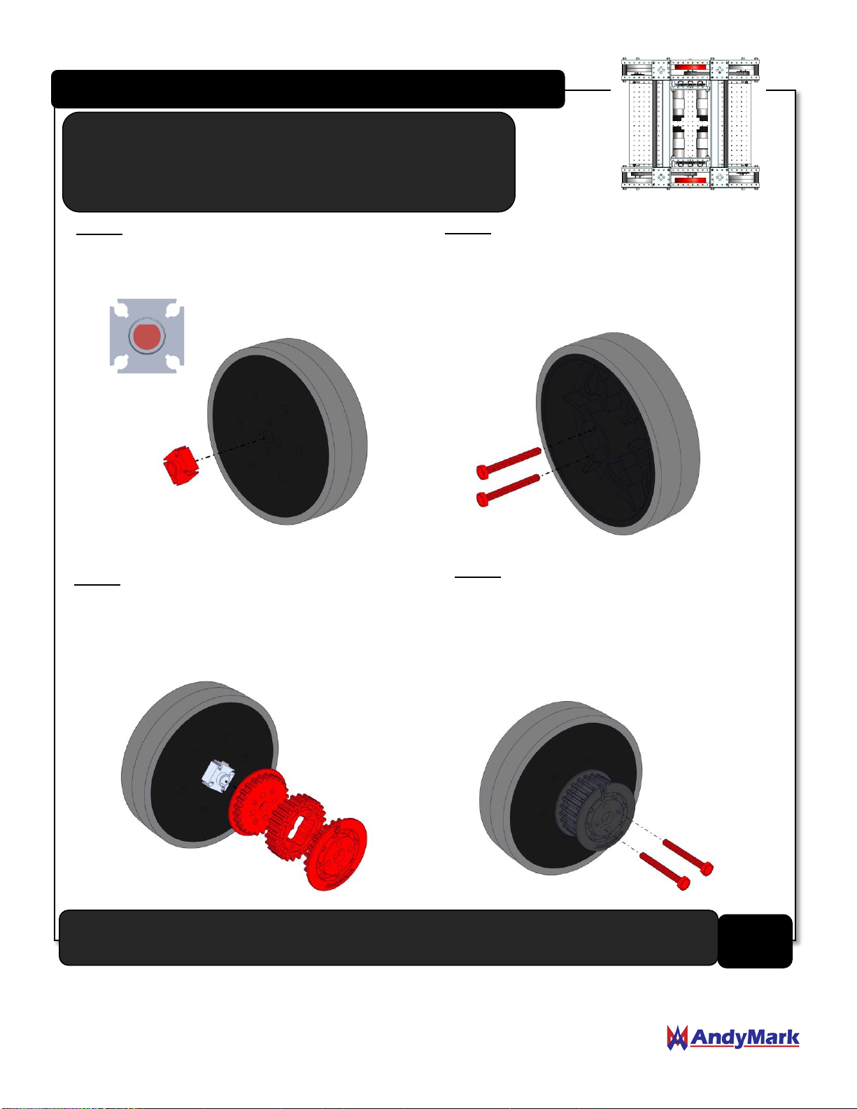
Center Wheel Assembly Instructions (QTY 2)
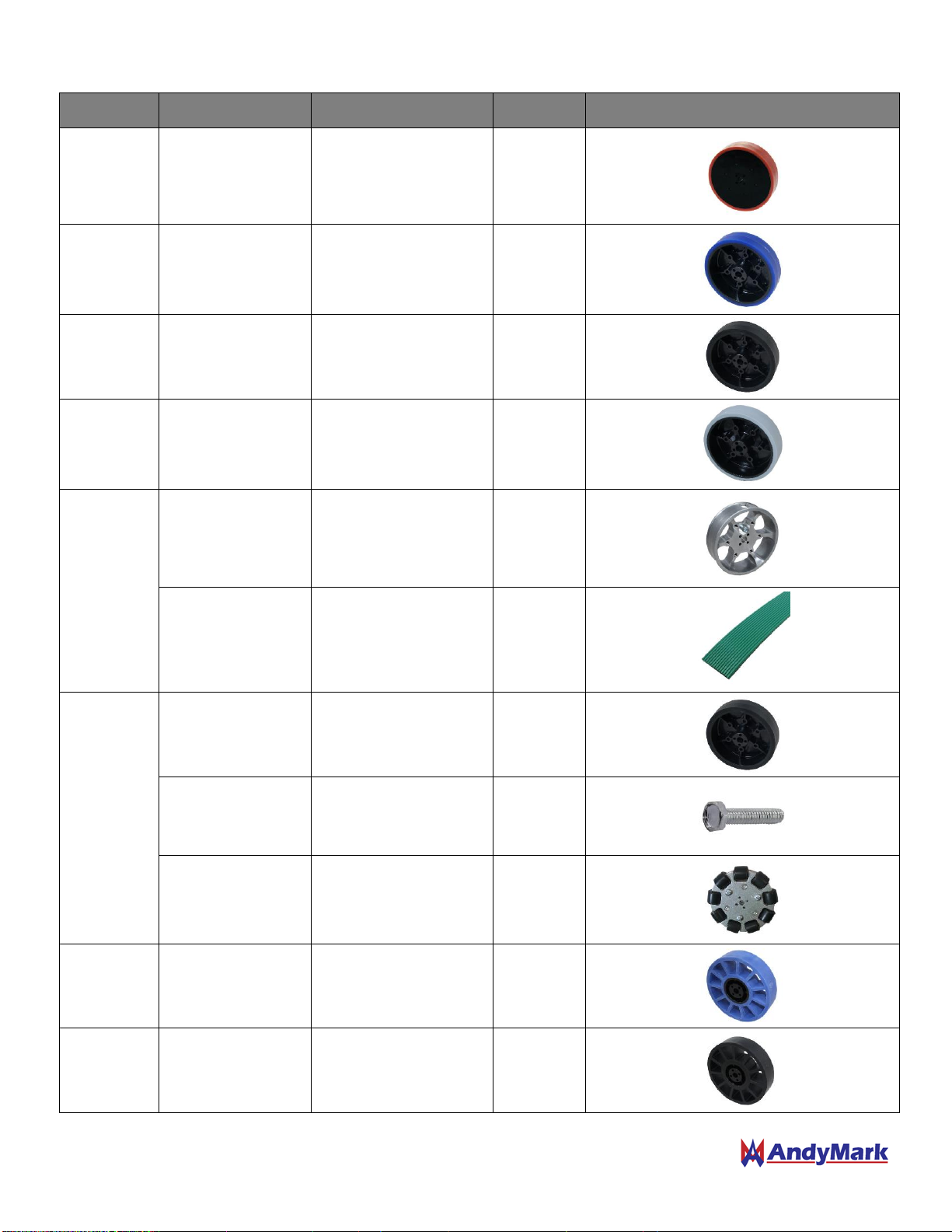
Step 1: Place a 6mm D-Bore Double Boss Nub
(am-3215a) into the center bore of a 4" 8mm
Bore Wheel on the flat side of the wheel.
Step 2: Flip the wheel over and secure the
Nub to the wheel by threading two 6-32 x
1.25 in Hex Head Screws (am-1437) into
the Nub. Be sure to place the 6-32 screws
in opposite holes of the wheels.
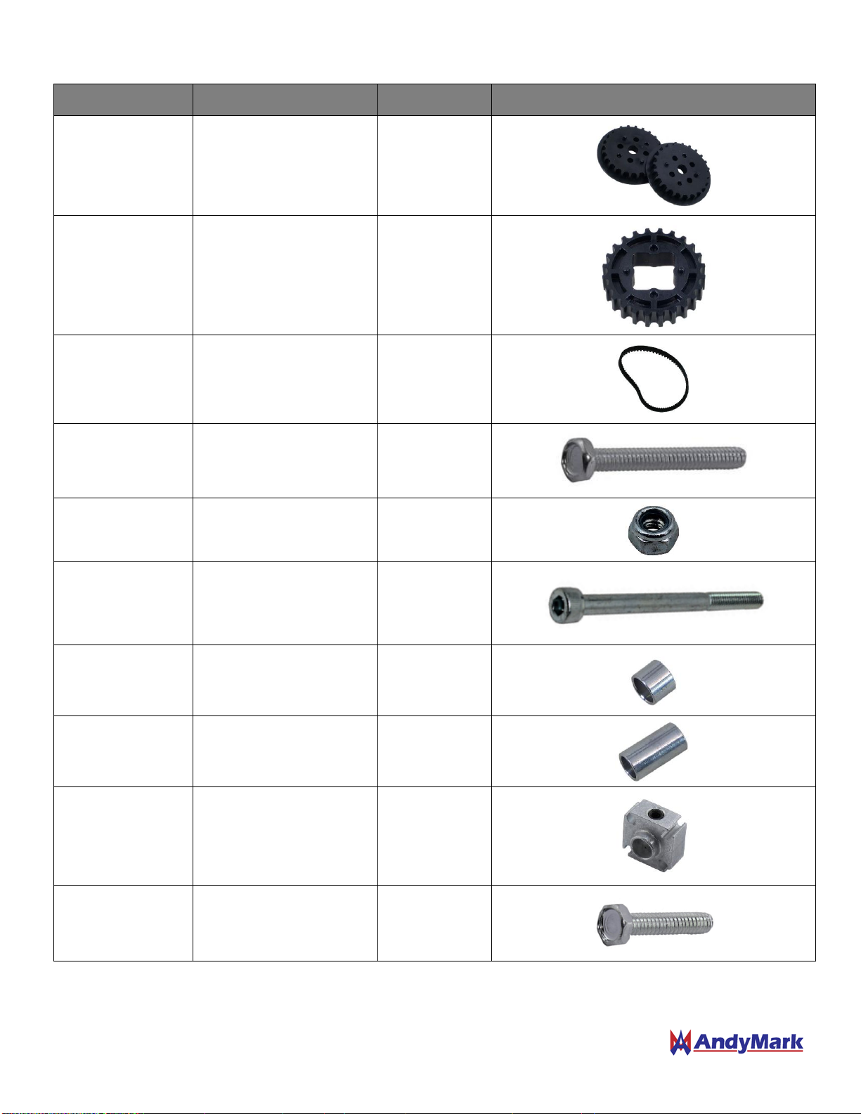
Step 3: Place a 24 Tooth HTD Pulley Extender
(am-3404) between two 24 Tooth HTD Pulley
Halves (am-3401_half), and place all three
components onto the boss of the Nub.
Step 4: Align the bolt circles of the Nub and the
Pulley Assembly, and secure the pulley by
threading two 6-32 x 1.25 in Hex Head Screws
(am-1437) into the Nub. Be sure to thread the
screws into the opposite holes that were used to
secure the Nub to the Wheel.
Repeat one more time to make 2 total Center Wheel Assemblies.
NOTE: This subassembly applies to any 6WD TileRunner
configuration utilizing a Stealth, Performance, or
Compliant Wheel as the center wheel. See Page 20 for
Performance Wheel Assembly Instructions.