Phoenix Mecano HARTMANN ELECTRONIC PXCe4006 Series User manual

www.hartmann-electronic.com Rev. 1.2 1
PXIe Chassis
PXCe4006 6 Slot 1U 19”
High Power Version
User Manual

www.hartmann-electronic.com Rev. 1.2 2
Revision History
Version:
Notification of Change
Date
(Revision) Author
0.2
18.01.2018
J. Brosowski
0.3
28.11.2018
J. Brosowski
1.0
Add Software Support for multi-vendor interoperability.
Add Fan control
13.05.2019
J. Brosowski
1.1
Power Supply update
04.12.2019
J. Brosowski
1.2
Power Supply Update
17.03.2020
J. Brosowski
Imprint:
Hartmann Electronic GmbH
Motorstraße 43, D-70499 Stuttgart (Weilimdorf)
Telephone: +49 711 1 39 89-0
Telefax: + 49 711 8 66 11 91
Internet: www.hartmann-electronic.com
Hartmann Electronic is a longstanding partner of the
Embedded industry and has a variety of different backplanes.
With our wide selection of backplanes and enclosure you can
Build your perfect system platform
Copyright © 2017
All rights and technical modifications reserved

www.hartmann-electronic.com Rev. 1.2 3
Contents
1. Safety.....................................................................................................................................................................5
Intended Application..............................................................................................................................................5
Safety Symbols .....................................................................................................................................................5
General Safety Precautions ..................................................................................................................................5
Safety Instructions.................................................................................................................................................6
Protection Against Electromagnetic Interference (EMI) .....................................................................................6
Electrostatic Discharge Precautions...................................................................................................................6
Installation ..........................................................................................................................................................6
Location..............................................................................................................................................................6
Voltage Hazards.................................................................................................................................................6
System Overheating...........................................................................................................................................6
Mounting Considerations....................................................................................................................................6
Electrical Hazards...............................................................................................................................................7
Board Installation................................................................................................................................................7
2. Product Description ...............................................................................................................................................8
Related Documentation.........................................................................................................................................8
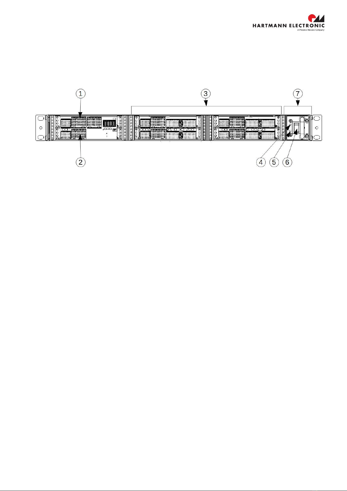
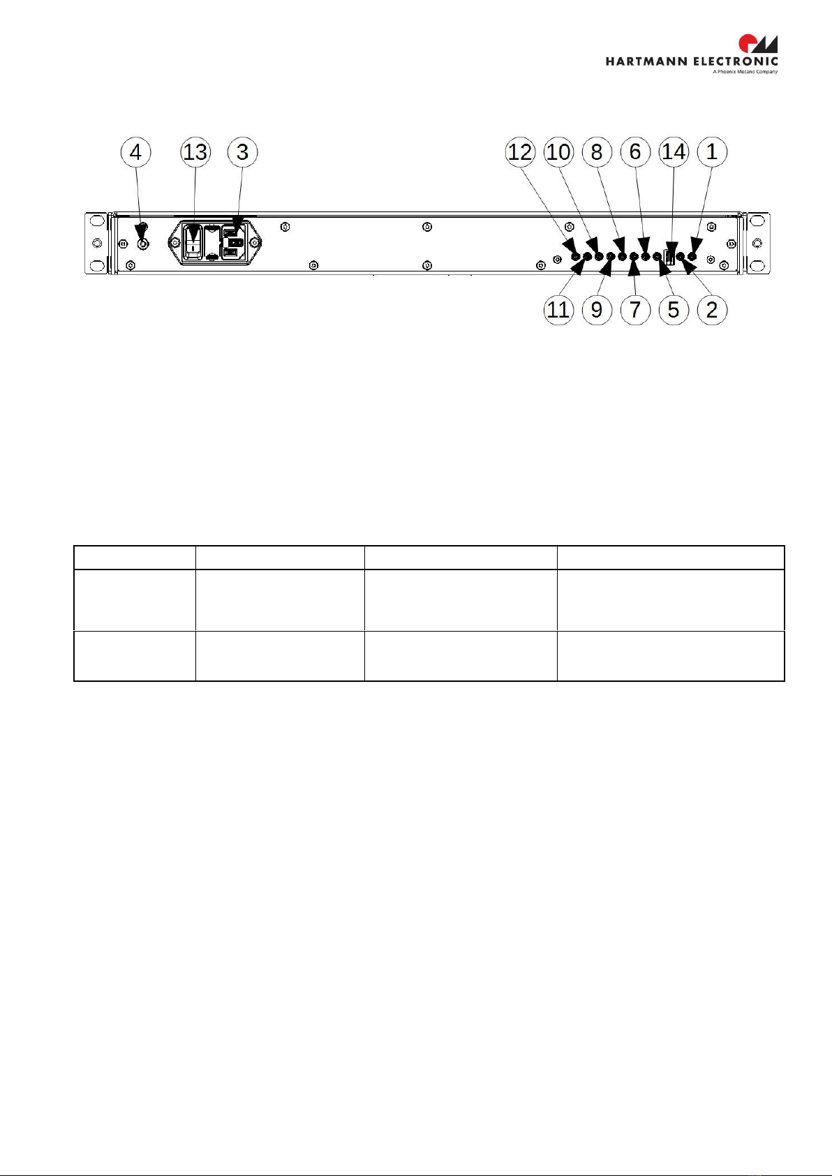
Chassis Description...............................................................................................................................................9
Fan Control..........................................................................................................................................................10
System Controller Slot.........................................................................................................................................12
PXIe Peripheral Slot............................................................................................................................................12
Hybrid Peripheral Slots........................................................................................................................................12
PCI Express Backplane Diagram........................................................................................................................13
PXI Local Bus......................................................................................................................................................13
PXI Trigger Bus...................................................................................................................................................14
System Reference Clock.....................................................................................................................................14
Front Panel LEDs................................................................................................................................................16
Interoperability with CompactPCI........................................................................................................................16
3. Installation............................................................................................................................................................17
Connecting Chassis Grounding ..........................................................................................................................17
Inspecting the Chassis Components...................................................................................................................17
Protection Against Electromagnetic Interference................................................................................................17
Installing Hardware..............................................................................................................................................18
Installing Software...............................................................................................................................................19
4. Maintaining the Chassis.......................................................................................................................................20
Replacing the Fan Tray.......................................................................................................................................20
5. Service.................................................................................................................................................................21
Technical support and Return for Service Assistance ........................................................................................21
Declaration of Conformity....................................................................................................................................21
6. Specification ........................................................................................................................................................22
Electrical..............................................................................................................................................................22
AC Input............................................................................................................................................................22
DC Output.........................................................................................................................................................22
Power available for Backplane.........................................................................................................................22
System Synchronization Clocks.......................................................................................................................23
Operating Environment ....................................................................................................................................23
Cooling Capacity ..............................................................................................................................................24
Electromagnetic Compatibility..........................................................................................................................26
Mechanical .......................................................................................................................................................27
Recessed Mounting..........................................................................................................................................29
Cooling ................................................................................................................................................................30
Airflow...............................................................................................................................................................30
Chassis Material..................................................................................................................................................30
Humidity...............................................................................................................................................................30
Operational Shock...............................................................................................................................................30
Random Vibration................................................................................................................................................30
Safety ..................................................................................................................................................................30
7. Pin Assignment....................................................................................................................................................31
System Controller Slot (4 Link Configuration).....................................................................................................32
PXI Express Hybrid Peripheral Slot ....................................................................................................................33

www.hartmann-electronic.com Rev. 1.2 4
PXIe Peripheral Slot............................................................................................................................................35
8. Ordering Information............................................................................................................................................36

www.hartmann-electronic.com Rev. 1.2 5
1. Safety
Intended Application
PXI Express PXCe4006 series chassis are not end-products with independent functionality according the
EMC regulations, an operational system is achieved only by combining the chassis with appropriate plug-
in PCI/PXIe instruments. As a consequence formal certification requirements as the for instance the CE
marking do not apply to it.
The completion and final testing of the units has to be carried out, or at least supervised, by a qualified
technician. The following instructions are directed exclusively to this qualified personal, i.e. engineers,
trained and qualified electricians etc.
Make sure that the finished system complies with the safety regulations currently applicable in the
country in which it will be used.
Safety Symbols
Hazardous voltage!
Familiarise yourself with the danger of electrical voltages and the safety
precautions before starting to work with parts that carry dangerous voltages
Caution!
This symbol indicates a condition where damage of the equipment or injury of
the service personnel could occur. To reduce the risk of damage or injury,
follow all steps or procedures as instructed.
Danger of electrostatic discharge!
Static electricity can damage sensitive components in a system. To avoid
damage, wear ESD wrist straps or at regular intervals touch blank enclosure
parts.
General Safety Precautions
Warning!
Voltages over 60 VDC can be present in this equipment. This equipment is
intended to be accessed, to be installed and maintained by qualified and trained
service personnel only.
This equipment is designed in accordance with protection class 1!
lt must therefore be operated only with protective GND/earth connection!

www.hartmann-electronic.com Rev. 1.2 6
Safety Instructions
The intended audience of this User's Manual is system Integrators and hardware/software engineers.
The product has been designed to meet relevant standard industrial safety requirements. It must not be
used except in its specific area of office telecommunication industry and industrial control. It shall not be
used in safety-critical applications, life-sustaining appliances or in aircraft.
Only trained personnel or persons qualified in electronics or electrical engineering are authorized to
install, operate or maintain the product.
This section provides safety information about:
•Protection Against Electromagnetic Interference (EMI)
•Electrostatic Discharge Precautions
•System Installation
Protection Against Electromagnetic Interference (EMI)
The product has been tested and found to comply with the limits for a Class A digital device, pursuant to
part 15 of the FCC Rules, EN 55022 Class A.
To ensure proper EMC shielding, operate the chassis only with all free slots populated with filler panels.
Ensure that all EMI gaskets make correct contact.
Electrostatic Discharge Precautions
Electronic components can easily be destroyed by electrostatic discharge which can occur between
chassis components and a person.
•Before working on the chassis make sure that you are working in an ESD-safe environment.
Installation
To avoid chassis damage verify that the system environment meets the environmental and power
requirements given in this guide before installation consider these guidelines:
Location
Locate the system in a stable area free of excessive movement and jarring, dust, smoke, and
electrostatic discharge (ESD). Make sure that the temperature does not exceed the operating
temperature given in the environmental requirements in this guide and allow room for proper air flow for
cooling.
Voltage Hazards
The system is powered with a power supply the mains voltage is 115/230VAC.
(Voltage range 90VAC to 264VAC)
This voltage is considered hazardous.
System Overheating
Ensure clearance of at least 10 cm to the air inlet on the left side of the chassis, and a free path of at
least 10 cm for the air exhaust on the right.
Shelf ambient temperature may not exceed 50°C.
Mounting Considerations
During the course of handling, shipping, and assembly, parts could become loose or damaged.
Do not operate a shelf in this condition, as this may cause damage to other equipment.

www.hartmann-electronic.com Rev. 1.2 7
Electrical Hazards
The caution label on the system's rear near the grounding studs shows that you have
to create an earth connection because there may be a high leakage current which is considered
hazardous.
High leakage current can cause injuries.
Ensure that the system is properly grounded at all times, the following conditions shall be met:
•This equipment shall be connected directly to the AC supply system earth ground
Board Installation
Electrostatic discharge and incorrect board installation or removal can damage circuits or shorten their
life.
•Before touching the boards or electronic components, make sure that you are working in an ESD-
safe environment
Boards should be inserted and removed using their handles, do not force the board by applying pressure to
the front panel.

www.hartmann-electronic.com Rev. 1.2 8
2. Product Description
The PXCe4006 series Chassis is a six Slot PXI Express Chassis. The Chassis fully complies with the PXI-5 PXI
Express Hardware Specification.
To reduce space in modern test systems the PXCe4006 features a very compact 1U 19” design. There are one
PXIe System Slot, one PXIe Peripheral Slot and four fully Hybrid peripheral slots available. This provides the user
the highest flexibility to configure his test system with PXI and PXI Express.
The key features of the PXCe4006 Series Chassis include the following:
-Optional Rear Panel PXI_TRIG[7:0] SMB I/O Connector
-Rear Panel PXI_CLK10 I/O Connector
-Removable Fan Tray to reduce MTTR
-Complies with PXI and CompactPCI Specification
-0-50°C Temperature Range
-The PCI bus VIO is available with +3.3V and +5V
-On/Standby momentary power switch on the front panel for easy use
-Low jitter PXI Express Clocks with 25 ppm stability
-Software multi-vendor interoperability
-Module multi-vendor interoperability
Related Documentation
-PXI-5 PXI Express Hardware Specification
-CompactPCI PICMG 2.0 R. 3.0
-CompactPCI Express Specification PICMG EXP.0 Revision 2.0

www.hartmann-electronic.com Rev. 1.2 9
Chassis Description
Figure 2-1 Front view of the PXCe4006 series Chassis
1
System slot
5
Power LED
2
PXIe peripheral slot
6
On/Standby momentary power switch
3
PXIe hybrid slots
7
Removable fan tray
4
Fan LED

www.hartmann-electronic.com Rev. 1.2 10
Figure 2-2 Rear view of the PXCe4006 series Chassis
1
10 MHz REF IN SMB
6
PXI_TRIG[1] SMB
11
PXI_TRIG[6] SMB
2
10 MHz REF OUT SMB
7
PXI_TRIG[2] SMB
12
PXI_TRIG[7] SMB
3
AC-Input
8
PXI_TRIG[3] SMB
13
OFF/Standby Power Switch
4
Chassis Ground Screw
9
PXI_TRIG[4] SMB
14
Dip Switch Auto Mode/Fan Control
5
PXI_TRIG[0] SMB
10
PXI_TRIG[5] SMB
14 - Dip Switch Settings
Position
Function
ON
OFF
Position 1
Power Control
Auto Mode
Chassis is turned on through
the AC-Power Switch
Chassis can be turned on and off
through the momentary switch (6)
at the front Panel
Position 2
Fan Control
The Chassis' cooling fans are
running at full speed
Fan control is enabled
Fan Control
The Chassis’Cooling Fans are controlled through two temperature sensors. One sensor is located left next to the
System Controller Slot. The other temperature sensor is located right next to the System Controller Slot. If there
is a difference between the measured temperatures of one of each temperature sensors, the Fan controller
adjust the rotation speed of the fans according to the higher measured temperature value. The Fans are running
at lowest speed at a temperature of 24 °C or less. If the temperature reaches 52 °C or more the fans are running
at highest rotation speed.
Figure 2-3 shows the fan control curve

www.hartmann-electronic.com Rev. 1.2 11

www.hartmann-electronic.com Rev. 1.2 12
System Controller Slot
The System Controller slot is Slot 1of the chassis and is a 4-Link configuration system slot as defined in
CompactPCI Express and PXI Express Specification.
The backplane connects the system slot using three times PCIe X4 to the peripheral slots. One PCIe link of the
system slot connects to a PCIe Switch using PCIe Gen 2 X1. This switch distributes PCIe Gen2 X1 connection to
one fully PXIe Hybrid Slot, one PXIe Peripheral Slot and a PCIe to PCI Bridge. The PCIe to PCI bridge provides
PCI connection to the PXIe hybrid slots.
The PXIe hybrid slots 3-6 are connected to the PCI Bus. The PCIe- to PCI bridge provides a 32-bit, 33Mhz PCI
Bus.
The system controller slot has also connectivity to PXI_CLK10, PXI Trigger Bus and PXI Local Bus 6.
The mechanical momentary switch at the front panel transitions the PWRBTN# from open-circuit to GND to open
circuit. The system board uses this ON/OFF state to control the PS_ON# signal. The PS_ON# signal turns on the
chassis’ main power supply.
Alternatively, the chassis can be turned on without the momentary switch on the front panel. Therefore the auto
mode of the chassis has to be turned on. The auto mode can be turned on by changing the DIP-Switch’s position
1, on the chassis’ rear panel, into the ON-state.
PXIe Peripheral Slot
The chassis provides one PXIe peripheral slot 2. The peripheral slot is fully compliant with the PXI-5 PXI Express
Hardware Specification. The backplane connects the PCIe Switch using PCIE Gen2 X1 to the PXIe peripheral
slot. The PXI Express peripheral slot can accept the following modules:
-A PXI Express peripheral module.
-A PXI Express hybrid peripheral module.
-A CompactPCI Express Type-2 Peripheral module.
-A CompactPCI 32-bit peripheral with +3.3 V or +5 V V(I/O).
Hybrid Peripheral Slots
The PXCe4006 provides 4 PXIe hybrid peripheral slots that are fully compliant with the PXI-5 PXI Express
Hardware Specification. The PXI Express hybrid peripheral slots can accept the following modules:
-A PXI Express peripheral module.
-A CompactPCI Express Type-2 Peripheral module.
-A hybrid-compatible PXI peripheral module that has been modified by replacing the J2 connector with an
XJ4 connector installed in the upper eight rows of J2. Refer to PXI Express specification for details. The
PXI peripheral communicates through the backplane’s 32-bit PCI bus.

www.hartmann-electronic.com Rev. 1.2 13
PCI Express Backplane Diagram
Figure 2-4 shows the PXCe4006 series backplane’s PCIe interface.
Slot 3, 4 and 6 are connected with the system slot using PCIe X4. These slots have up to 2 GB/s (single
direction) dedicated bandwidth (X4 Gen-2 PCI Express).
Slots 2 and 5 are connected with the system slot using PCIe X1. These slots have up to 500MB/s (single
direction) dedicated bandwidth (X1 Gen-2 PCI Express).
PXI Local Bus
The PXIe backplane local bus is a daisy-chained bus, that connects each peripheral slot with adjacent peripheral
slots to the left and right.
The backplane routes PXI Local Bus 6 between all slots. The left Local Bus 6 from Slot 1 is not routed anywhere
and the right local bus signal from slot 6 is not routed anywhere.
Local bus signals may range from high-speed TTL signals to analog signals as high as 42 V.

www.hartmann-electronic.com Rev. 1.2 14
PXI Trigger Bus
All slots share eight trigger lines.
Figure 2-5 shows the PXCe4006 series backplane’s Trigger interface.
System Reference Clock
The PXCe4006 Chassis chassis supplies PXI_CLK10, PXIE_CLK100, and PXIE_SYNC100 independently driven
to each slot.
PXI_CLK10, PXIe_CLK100 and PXIe_SYNC100 have the default timing relationship according to PXI-5 PXI
Express Hardware Specification.
The timing relations are as shown in Figure 2-6.
The PXCe4006 Series Chassis provides an external 10 MHz, PXI_CLK10 SMB Clock input. If a Clock signal is
detected on the rear panel SMB connector, the backplane automatically phase-locks the PXI_CLK10,
PXIE_CLK100, and PXIE_SYNC100 signal to this external clock input and distributes the clocks to all slots.
Additionally a 10 MHz clock is distributed through the backplane to an external SMB Connector (10 MHz Clock
Out).
The backplane allows the 10 MHz reference clock to be derived from an external SMB clock input or an internal
clock oscillator.
Figure 2-7 shows the Clock architecture of the PXCe4006 Series Chassis.

www.hartmann-electronic.com Rev. 1.2 15
The PLL is connected to the SMB 10 MHz input clock if the input clock is present. The presence of the input clock
is automatically detected. If there is no input clock present, the clock source to the PLL is a 10 MHz Clock
oscillator.
Each of the clocks PXI_CLK10, PXIE_CLK100, and PXIE_SYNC100 are driven with an independent buffers.

www.hartmann-electronic.com Rev. 1.2 16
Front Panel LEDs
Figure 2-8 shows the location of the front panel LEDs.
Table 2-1 describes the front panel LED states
LED
State
Description
Fan LED
Off
Chassis is powered off
Red
One or more chassis fans have failed
Power LED
Off
Chassis is powered off
Green
Power supply is active, and all voltages are within normal operating ranges.
Interoperability with CompactPCI
The PXCe4006 series chassis allows you the flexibility to use the following devices in a single PXI Express
system:
-PXI Express compatible products
-CompactPCI Express compatible Type-2 peripheral products
-PXI hybrid slot compatible products
-Standard CompactPCI peripheral products
-
The PCI Clock has a frequency of 33 MHz. Therefore, the M66EN Pin of the CompactPCI bus is tied to Ground
at the backplane.
The VIO Voltage is either +5V or +3.3V. Refer to the CompactPCI PICMG 2.0 R. 3.0 specification for details
regarding V(I/O) and frequency selection.

www.hartmann-electronic.com Rev. 1.2 17
3. Installation
Connecting Chassis Grounding
The system contains gaskets at the chassis and board level to guard against electromagnetic
interference (EMI). Each of the chassis’ individual components makes contact with the gaskets and to the
PE-stud on the rear panel.
The card guides are outfitted with electrostatic discharge (ESD) contacts on each rail. These ESD
contacts ensure that the boards are fully discharged as they are plugged into the chassis in order to
prevent static build-up.
Caution!
The chassis is designed in accordance with protection class1l! lt must therefore
be operated with protective earth/GND connection. Use only a three conductor
AC power cable with a protective earth conductor that meets the IEC safety
standards!
There is a 4 mm stud on the rear panel. This stud is only for potential equalization. Proper grounding is
achieved through the protective earth conductor of the power cable!
Inspecting the Chassis Components
During the course of handling, shipping, and assembly, pins, shrouds, mounting screws, fans and other
items can become damaged and/or loose.
WARNING: Before utilizing the chassis, perform a thorough inspection to ensure the
chassis and its components are not damaged.
•To inspect the chassis:
1. Visually inspect the chassis to ensure that all of the connector pins are straight, screws are tight, and
so on.
2. Check to ensure none of the EMI gaskets is damaged.
Protection Against Electromagnetic Interference
The chassis contains gaskets at the shelf and board level to guard against electromagnetic interference
(EMI). Ensure that the chassis is grounded and that each of the chassis individual components make
contact with the gaskets.
Follow the proper grounding and ESD handling procedures.

www.hartmann-electronic.com Rev. 1.2 18
Installing Hardware
1.) Attach input power to the rear AC input using an appropriate AC power cable before installing the system
controller.
2.) Install the PXIe Remote Controller into the system controller slot. Slot 1 is indicated with the red card
guides. First, place the system controller into the front of the card guides. Slide the Remote Controller
into chassis, making sure that the injector handle is pushed down.
3.) When you begin to feel resistance, pull up on the injector handle to seat the system controller fully into
the chassis frame. Secure the system controller front panel by tightening the front panel mounting
screws.
4.) Install the peripheral modules into the appropriate slots.
WARNING: Boards should slide easily when installing or removing them from the
shelf. Forcing the boards may cause damage to the interface connector pins.
5.) Install filler panels in unused or empty slots.
Filler panels consists of a front panel (with or w/o air baffles), EMC gasket and mounting screws.
WARNING:
Close all empty chassis slots with filler panels. The filler panel prevents fan air from
escaping out open slots.
6.) Connect the PXIe Remote controller with your PC as shown in the concerning user manuel.
7.) Turn on the power switch at the rear panel to turn the chassis into standby state.
Before inserting boards, power the shelf to ensure that it is operating properly. The power connections
and the mains switch are located at the bottom right rear of the shelf
•Ensure that the AC switch is set to the off (O) position.
•Connect the mains AC cable (C14, 10 Amp, not supplied) to the AC inlet.
•Ensure that the mains AC feed (90-264VAC, 47-63Hz) is on.
•Turn the AC switch to the on (I) position. All the system fans will begin to operate.
8.) Turn on the chassis through the momentary power switch at the front panel. The chassis must be
powered up before the host PC is powered up.
9.) Turn on your connected host PC.

www.hartmann-electronic.com Rev. 1.2 19
Installing Software
In order to achieve vendor software interoperability, an installation package is provided with the PXCe4006 series
chassis.
It is recommended that the NI PXI Platform Services is installed before the Hartmann Electronic installer is
executed. Make sure that the installer is executed within its original folder location.
After running the Hartmann Electronic installer the PXCe4006 series chassis is automatically detected through
the National Instruments Measurement and Automation Explorer as shown in the Image below.

www.hartmann-electronic.com Rev. 1.2 20
4. Maintaining the Chassis
Replacing the Fan Tray
The fan tray can be accessed from the front on the right side of the chassis.
Removing the Fan Tray
•Loosen the four mounting screws (top and bottom) on the front of the fan tray.
•With the fan tray handle, pull the fan tray out partially toward the front of the shelf until the interface
connector disengages. Wait until the fans have stopped and then remove the fan tray from the shelf.
•
WARNING:
Extreme care should be taken while handling the fan tray. It is recommended to wait
until the fan’s open impellers have stopped spinning before removing the fan tray.
Installing the Fan Tray
•Insert the replacement fan tray into the shelf and ensure that the interface connectors align. Insert
the fan tray gently until fully seated.
•Tighten the two mounting screws (top and bottom) on the front of the fan tray.
This manual suits for next models
1
Table of contents
Other Phoenix Mecano Chassis manuals