Warning: The circuits connected to terminals AX1, AX2, COM, SIG, and +V are not isolated from the
DIRECTION
SWITCH
STOP
SWITCH
AC LINE
VOLTAGE
115 / 230 VAC
10K OHM
SPEED ADJUST
POTENTIOMETER
CW
ENABLE / INHIBIT
SWITCH
MOTOR
Speed Poten�ometer / Analog Signal
Direc�on (AX1)
S
Inhibit / Enable (AX2)
Do not use the inhibit or enable for emergency stopping.
Line Input
Motor
Connections
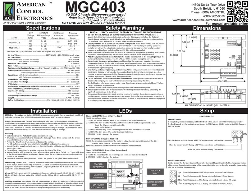
SCCR (Short Circuit Current Ra�ng):
Branch Circuit Protec�on: Branch Circuit Protec�on: Class J, Class CC, or Class T fuses are to be rated
Moun�ng
•
• Components a
•
• The chassis should be earth g
Heat Sinking:
Wiring: °
Shielding Guidelines:
Installation
S]
3.64 [93]
3.00 [76]
1.25 [32]
0.50 [13]
3.80 [97]
4.30 [110]
1.34 [34]
0.95 [24]
Dimensions
DO NOT INSTALL, REMOVE OR REWIRE THIS EQUIPMENT WITH POWER APPLIED.
Circuit poten�als are at 115 or 230 VAC above earth ground
It is strongly recommended to install a master power switch in the line voltage input. The switch
contacts should be rat
Removing AC line power is the only acceptable method for emergency stopping. Do not use
m
Do not disconnect any of the motor leads from the drive
•
•
•
•
•
•
•
•
•
•
READ ALL SAFETY WARNINGS BEFORE INSTALLING THIS EQUIPMENT
Safety Warnings
WARNING:
*
AC Line SourceØ
AC Line Current
Accelera�on Time Range seconds
Decelera�on Time Range seconds
Input Impedance (COM to SIG)
Analog Input Signal Range (isolated) to ±
Form Factor
Load Regula�on of base speed
Speed Range
Maximum Vibra�on 0 - 50 Hz (>50 Hz) G)
Surrounding Air Temperature Range
Weight
Safety Cer�fica�ons
1/50 - 1/8
1/25 - 1/4
1/8 - 1
1/4 - 2
1.5
11.0*
0 - 90
0 - 180
0 - 90
0 - 180
115
230
115
230
MGB400-1.5
MGB400-11
Armature
Horsepower
Range
Connuous
Armature
Current (Amps)
Armature
Voltage Range
(VDC)
Line
Voltage
(VAC)
Model
Specifications
14300 De La Tour Drive
South Beloit, IL 61080
Phone: (844) AMCNTRL
Fax: (800) 394-6334
www.amcntrl.com
MGB400
TM
4Q SCR Chassis Microprocessor-based
Adjustable Speed Drive with Speed
or Torque Mode for PMDC Brushed Motors


