Anest Iwata FCV-5-R1 User manual

1
重要仕様
最高使用圧力 液体 : 1.0MPa エア : 0.6MPa
使用温度範囲 雰囲気温度5℃〜40℃ 流体温度5℃〜43℃(液体、気体)
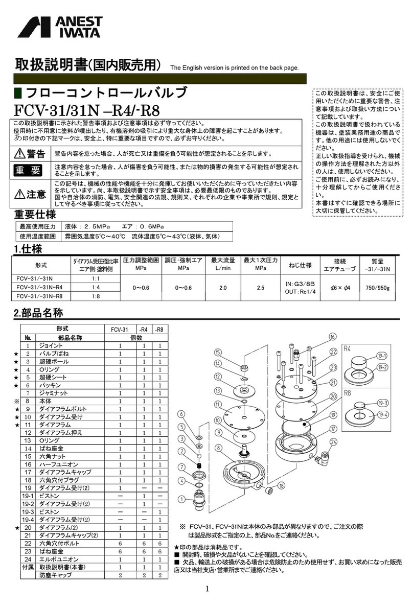
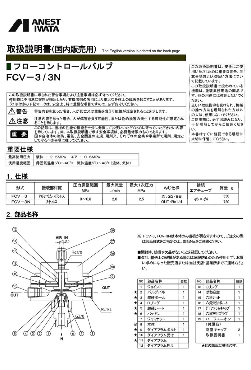
フローコントロールバルブ
FCV-5-R1/-R4/-R8
1.仕様
形式 オペレートエア受圧径比率
エア側:塗料側
圧力調整範囲
MPa
調圧・強制エア
MPa
最大流量
L/min
最大1次圧力
MPa ねじ仕様 接液部材質 質量
FCV-5-R1 1:1 0〜0.6
0〜0.6 2.0 1.0
IN:G1/4B
OUT:G1/4B
AIR:Rc1/8
SUS
PTFE 580g
FCV-5-R4 1:4
FCV-5-R8 1:8
2.部品名称
※ No.18、19は形式によって部品が異なります。
N0.22、24は必要に応じて取り付けてください。
★印の部品は消耗品です。
■開封時、破損や欠品がないことを確認してください。
■欠品、輸送上の破損がある場合は危険防止のため使用せず、お買い求めになった販売店又は
当社支店・営業所までご連絡ください。
この取扱説明書に示された警告事項および注意事項は必ず守ってください。
使用時に不用意に塗料が噴出したり、有機溶剤の吸引により重大な身体上の障害を起こすことがあります。
印付きの下記マークは、安全上、特に重要な項目ですので、必ずお守りください。
警告内容を怠った場合、人が死亡又は重傷を負う可能性が想定されることを示します。
注意内容を怠った場合、人が傷害を負う可能性、または物的損害の発生する可能性が想定され
ることを示します。
この記号は、機械の性能や機能を十分に発揮してお使いいただくために守っていただきたい内容
を示しています。尚、本取扱説明書で示す安全事項は、必要最低限のものであります。
国や自治体の消防、電気、安全関連の法規、規則又、それぞれの企業や事業所で規則、規定と
して守るべき事項に従ってください。
この記号は注意内容を怠った場合、衛生上のトラブルから、社会的な企業責任の追及と信用の
消失、甚大な損害賠償、入院患者の発生、生産品のリコール、又は消費者からの苦情を招く可能
性があることを示します。
形式 FCV-5-R1 -R4 -R8
№ 部品名称 個数
1 座金六角穴ボルト 4 4 4
2 プラグ 1 1 1
3 循環ベース 1 1 1
★4Oリング 1 1 1
★5芯棒 1 1 1
★6シート 1 1 1
7 ジョイント 2 2 2
8本体 1 1 1
9ダイアフラム受け 1 1 1
★10 ダイアフラム 1 1 1
★11 Oリング 1 1 1
12 ダイアフラム押し 1 1 1
13 六角ナット 1 1 1
14 ダイアフラムキャップ 1 1 1
15 ピストン 1 1 1
16 ダイアフラムキャップ(2) 1 1 1
★17 Oリング 1 1 1
※ 18-1 ピストンガイド R1 1 − −
※ 18-2 ピストンガイド R4 −1−
※18-3 ピストンガイド R8 − − 1
※19-1 ピストン R1 1 − −
※19-2 ピストン R4 −1−
※19-3 ピストン R8 − − 1
★20 ダイアフラム(2) 2 2 2
21 ヘッド 1 1 1
22 ステー(付属品) 1 1 1
23 六角穴付きボルト 4 4 4
24 六角穴付きボルト(付属品)2 2 2
25 六角穴付きプラグ 1 1 1
付属 取扱説明書(本書) 1 1 1
ジョイント(No.7 と同一) 1 1 1
この取扱説明書は、安全にご使
用いただくために重要な警告、注
意事項および取扱い方法につい
て記載しています。
この取扱説明書で扱われている
機器は、液体の調圧に使用する
商品です。他の用途には使用し
ないでください。
正しい取扱指導を受けられ、機械
の操作方法を理解された方以外
の人は、使用しないでください。
ご使用前に、必ずお読みになり、
十分理 解してからご使 用くだ さ
い。
本書はすぐに確認できる場所に
大切に保管してください。
(国内販売用)
衛 生
※本製品は食品用途にご使用いただくことも可能ですが、
接液部に食品衛生法に準拠した材質を使用したり、汚染
しにくい構造にしているのが特長であって、抗菌作用が
ある訳ではありません。使用後のメンテナンスや除菌作業
等はお客様にて実施ください。

2
3.安全にご利用いただくための警告事項
人体保護
・作業中は、眼鏡、マスクおよび手袋などの保護具をかならず着用し、換気の良い
場所で使用してください。液剤が目に入ったり、ミストを吸い込む危険性があります。
作業中、身体に異常を感じたら、ただちに医師による治療を受けてください。
機器誤用
・使用する際は、各部の取付け、調整が適当かどうか確認後操作してください。
・絶対に人や動物に向けてスプレーしないでください。
目や皮膚の炎症、人体への危険があります。
・洗浄、分解、保守作業をする前には必ず液剤の圧力を0MPaにしてください。
圧力が残っていますと、誤動作、液剤の飛散により人体に危険があります。
・ホース、ポンプへの接続は、漏れや緩みがないように確実に接続してください。
作業中ホース等が抜け、液剤等の飛び跳ねによる傷害等重大な身体上の
危険があります。
ケガをした場合、ケガの大小にかかわらず、ただちに医師による治療を受けてください。
・最大1次圧力以下で必ず使用してください。
最大1次圧力以上で使用すると、機材が破損し、非常に危険です。
その他
・化学薬品用には使用しないでください。
塗料通路内部の腐食による事故や異物混入による健康障害の可能性があります。
異常を発見したら直ちに使用を停止して原因を調査してください。異常が解決されるまで再使用しないでください。
・製品の改造は絶対にしないでください。
・部品を交換する場合は、当社純正部品を必ず使用してください。
十分な性能が発揮できないばかりか、故障の原因となります。
・次のハロゲン化炭化水素系溶剤が、製品にかからないようにしてください。
塩化メチル、塩化エチル、ジクロルメタン、1.2-ジクロルエタン、四塩化炭素、トリクロルエチレン、1.1.1-トリクロルエタン
化学反応により、アルミニウム部品にクラック、溶解が発生します。
(特殊な塗料や溶剤などは十分適合性を検討した上でご使用ください。適合性検討のための材質リストを提出する用意があります。)
・購入後初めてご使用の場合は、液体通路内部の防錆油を取り除くため、無害で液体に適合する洗浄液を用いて内部の洗浄を行ってください。
食液用にご使用の場合、防錆油が残っていると食液が汚染され経口により健康障害の可能性があります。
・使用ごとに分解洗浄を行ってください。
構造上、循環洗浄のみでは十分に洗浄できない可能性があります。
4.接続方法及び操作方法
・ねじ穴にジョイントを接続したり、既存のジョイントを組み換える際はネジ部に中強度接着剤又はテープシールを使用し、液やエア漏れが発生しないようにしてください。
・使用する液体にはゴミ、異物などの混入がないよう注意してください。
異物が混入した液体を使用すると詰まりやシート漏れを起こし、吐出量が不安定になることがあります。具材の入った食液も同様です。
・液体供給圧力はオペレートエア圧力よりも0.05MPa以上高くなるよう設定してください。
液体供給圧力がオペレートエア圧力よりも低いと、吐出量が不安定になります。
接続例
手順-1 液剤供給口・出口に液剤ホースを確実に取付けます。
手順-2 エア減圧弁からのエアを通したエアチューブをオペレートエア供給口に接続します。
※1.洗浄時などに強制エアを使用される場合、六角穴付きプラグを外して組み換えます。
洗浄完了後は3方弁などを用いて強制エア圧力を逃がします。
※2.液剤を循環させる場合、プラグを外して組み換えます。
操作方法
・オペレートエアの圧力を上げると液剤2次圧力を高く設定できます。
・オペレートエアの圧力を下げ、2次圧力を逃がすと、2次圧力を低く設定できます。
・強制エアの圧力を上げるとオペレートエア受圧径比率に依らずバルブを開くことができ
ます。洗浄時など必要に応じて使用してください。
オペレートエア圧を上げた状態でバルブをより大きく開く場合は、強制エアの圧力を
オペレートエア圧より高く設定してください。
衛 生

3
オペレートエア圧力に対する噴出量参考値
5.分解と組立
・分解及び組立て手順は、FCV5-R1を代表でご説明致します。
FCV-5-R4/-R8では一部部品の形状と名称が異なりますが、分解・組立ての手順は同じです。
・芯棒、シート、ダイアフラムを分解した時は、摩耗やキズ、変形の有無を必ず確認してください。
摩耗やキズ、過度な変形がある場合はそのまま使用せず、新しい部品に交換してください。
・シートは、内テーパーと芯棒の球面が接する向きで本体に取付けてください。(右図参照)
また、Oリングやピストンなど、部品の入れ忘れに注意してください。
正しく組み立てられない場合、不具合や故障の原因となります。
・六角穴付きボルトや六角ナットを取付ける際、締め付け過ぎに注意してください。
強く締め付け過ぎるとダイアフラムや本体が破損する場合があります。
分解
手順-1
ヘッド上の座金六角穴ボルトを緩め、ヘッド、ダイアフラム(2)、
ピストンガイドR1、ピストンR1、ダイアフラムキャップ(2)、ダイアフラム(2)、ピストン、
ダイアフラムキャップを取り外します。
さらにキズや摩耗が見られる場合ダイアフラムキャップ(2)からOリング
を取り外します
手順-2 循環ベース下の座金六角穴ボルトを緩め、循環ベースを取り外しま
す。
手順-3
芯棒の六角部を固定して六角ナットを緩め、
ダイアフラム押し、ダイアフラム、ダイアフラム受け、心棒を外します。
さらにキズや摩耗が見られる場合Oリング、シートを取り外し
ます。
組立
手順-4 各部にキズ及び異物の付着が無いかを確認します。
異常があった場合、洗浄または部品を交換してください。
手順-5
外している場合は本体にシート、Oリングを取り付けます。
本体に芯棒を通した後、ダイアフラム受け、ダイアフラム、
Oリング、ダイアフラム押し、六角ナットを取付け、
芯棒の六角部を固定して六角ナットを締込みます。
手順-6 本体下部に循環ベースを取り付け座金六角穴ボルトを締込みます。
ボルトは対角線上に少しずつ均等に締めてください。
手順-7
外している場合はダイアフラムキャップ(2)にOリングを取り付けます。
ヘッドに座金六角穴ボルトを通し、ダイアフラム(2)、ピストンガイドR1、
ピストンR1、ダイアフラムキャップ(2)、ダイアフラム(2)、ピストン、ダイアフラムキャップ
を取り付けます。
手順-8
本体に手順7で組み立てた部品を取り付け、座金六角穴ボルトを
締め込みます。
ボルトは対角線上に少しずつ均等に締めてください。
テスト条件
・液剤供給圧力:0.5MPa
・ガン:WA-100-082P(ノズル口径 f0.8)
・粘度=12sec(NK-2)
・液剤ホース f4×f2.5-2m (FCV〜ガン)
推奨使用領域注)
FCV-5-R1 0.07MPa〜 ≧70 ml/min
FCV-5-R4 0.10MPa〜35〜150 ml/min
FCV-5-R8 0.12MPa〜 20〜100 ml/min
注)あくまで参考値ですので、塗料の性質やホース径等、
お客様の使用環境により異なります。
F
CV
-
5
-
R1
-
R4
-R8
吐出量 [ml/min]
オペレートエア圧力 [MPa]
向きに注意
注) FCV-5-R1 を例として説明します。

4
6.故障の原因と対策
☆印の処置は、お買いあげの販売店又はお近くの当社支店、営業所にご依頼ください。
正しい処置が行われない場合、十分な性能が発揮できなくなります。
現 象 原 因 対 策
2次圧力が上がりすぎる。 1.シートの当たり不良、ゴミ詰り 1.再組立、洗浄
2.シートの摩耗、キズ 2.交換 シート(NO.6)
3.芯棒の摩耗、キズ
4.ダイアフラムの変形
3.交換 芯棒(NO.5)
4.交換 ダイアフラム(NO.10)☆
外部に液剤が漏れる 1.ジョイント、プラグの緩み 1.組み直し、接着剤塗布
2.座金六角穴ボルトの緩み 2.締め増し
3.六角ナットの緩み 3.締め増し
4.ダイアフラムの破損 4.交換 ダイアフラム(NO.10)☆
5.Oリングの破損 5.交換 Oリング(NO.4,11)
2次圧力が上がらない 1.一次圧力が低い 1.一次側圧力を上げる
圧力が安定しない 1.ダイアフラムの変形 1.交換 ダイアフラム(NO.10)☆
※ 表中のNO.は、1頁の部品表の部品NO.を示します。
7.保証と修理サービス
・保証期間は、お買いあげの日から6ヶ月です。
・万一、故障の場合は、お買いあげの販売店又は当社支店・営業所にご連絡ください。
保証期間中は、無償修理いたします。
・無償保証を受けるための条件および手続き
本保証書をご提示の上、お買いあげの販売店、または当社支店・営業所・サービス会社にご依頼ください。
本保証書は日本国内においてのみ有効です。ThiswarrantyisvalidonlyinJapan
※本製品の故障または不具合に伴う生産補償、営業補償など二次損失に対する補償は致しません
ので、ご了承願います。
・次の場合は保証期間内でもお客様のご負担(有償)になります。
・取扱説明書の注意事項を守られなかったことによる故障および損傷
・お客様の取扱上の不注意による故障および損傷
・消耗品の交換・修理
・天災、地変、火災、地震、水害、塩害、落雷、公害などによる故障および損傷
・純正部品以外の部品が使用されている場合
・指定の修理店以外による修理がなされている場合
製品に関するお問い合わせ、ご意見・ご希望などございましたら、
当社お客様相談室までご連絡ください。
〒223-8501 横浜市港北区新吉田町3176
取説No.T851−00
コードNo.04008250
● お客様相談室
フリーダイヤル 0120-917-144
※携帯・PHS
からもご利用頂けます。
FAX 045-591-1137
当社支店・営業所は、当社ホームページをご確認下さい。
URL http://www.anest-iwata.co.jp

5
Flow Control Valve
Be sure to observe warnings and cautions in this instruction manual.
I not, it can cause liquid ejection and result in serious bodily injury.
Be sure to observe ollowing marked items which are especially important.
Indicates a potentially hazardous situation which, i not avoided, may result in serious injury or loss o lie.
Indicates a potentially hazardous situation which, i not avoided, may result in minor or moderate injury or property
da
mage.
Important Indicates notes which we ask you to observe. The saety precautions in this instruction manual are the minimum
necessary conditions. Follow national and local regulations regarding ire prevention, electricity and saety as
well as your own company regulations.
Hygiene Indicates i you do not pay attention to the contents, rom hygiene problems, you and your corporate can ace
social corporate responsibility, loss o social trust, compensation or damage, products recall and complaint rom
customers.
Important specifications
Max. Working Pressure Fluid / IN ; 1.0MPa / 10bar / 145PSI Fluid / OUT ; 0.6MPa / 6bar / 87PSI
Control. Air ; 0.6MPa / 6bar / 87PSI
Temperature range Atmosphere ; 5℃〜40℃Fluid / Air ; 5℃〜43℃
Main specifications
Model
Diaphragm
area ratio
Air side:Paint side
Max. primary
pressure
MPa/ bar
Adj. Air Pressure
range
MPa/ bar
Max. low
[L/min](cm)
Fluid & Air
Connection
Mass
[g](ibs)
Material o wet
section
FCV-5-R1 1:1
1.0/10 0 ~0.6 / 0 ~6 2.0
( 0.07 )
Fluid IN G1/4
Fluid OUT G1/4
Air tube Rc1/8
580
(1.3)
Stainless steel
Telon
FCV-5-R4 1:4
FCV-5-R8 1:8
Flow vs adj Air pressure
Adj Air Pressure [MPa]
FCV-5-R1 / -R4 / -R8
INSTRUCTION MANUAL
This Anest-iwata low control valve complies with ATEX
regulations 2014/34/EU,
Protection level :
Ⅱ2 G,Suitable or use in Zones 1 and 2.
X marking :
Any static electricity discharge rom the low control
valve is to be diverted to the grounded by connecting to
grounded pump or grounded luid pipelines or grounded
metal bracket as stipulated.
This manual contains IMPORTANT WARNINGS and INSTRUCTIONS.
Equipment in this manual is exclusively
or regulating luid pressure
purposes.
Do not use or other purposes.
The operator shall be ully conversant with the requirements stated in
this instruction manual including important warnings, cautions and
operation and correct handling.
Read and understand the instruction manual, beore use and retain
or reerence.
Testing conditions
・Fluid Input Pressure:0.5MPa
・Gun type:WA-100-082P(Nozzlef0.8)
・Viscosity=12sec(NK-2)
・Tube f4×f2.5-2m
Recommended flow range1)
FCV-5-R1 0.07MPa〜 over 70 ml/min
FCV-5-R4 0.10〜0.23MPa 35〜150 ml/min
FCV-5-R8 0.12〜0.25MPa 20〜100 ml/min
F
CV
-
5
-
R1
-
R4
-
R8
1) Reference value (varies depend on conditions)
II 2 G Ex h IIB T6 Gb X
This product uses materials that conorm to the
Japanese
Food
Sanitation Law in the wetted part, and it has a structure that is
easy to clean. So this can be used or soluble ingredients, but i
maintenance is insuicient, germs could be generated. Carry
out suicient maintenance and sterilization work ater use at
your own risk.
Flow [ml/min]
1

6
Safety precautions
1. Spark and open flames are strictly prohibited.
In some case, luid could be highly lammable and can cause ire.
Avoid any ignition sources such as smoking, open lames, electrical goods, etc.
2. Pay attention that it’s exterior does not come into contact with the following
Halogenated hydrocarbon solvents.
which can cause cracks or dissolution on gun body (aluminum) by chemical reaction.
unsuitable solvents:methyl chloride, dichloromethane, 1.2-dichloroethane,carbon tetrachloride,
trichloroethylene, 1.1.1-trichloroethane
(Be sure that all luids and solvents are compatible with parts.
We are ready to supply a material list used in the product)
3. Securely ground flow control valve, connecting to grounded pump or grounded fluid pipelines or grounded metal bracket.
Ground wire :Less than 1MΩ. Check the earth stability periodically.
I not, insuicient grounding can cause ire and explosion due to static electric sparking.
Wrong operation o equipment
1. Before operation, confirm that each section is properly fitted and adjusted.
Install the pressure relie valve inconnected piping route to letthe paints pressure relie in the emergency.
2. Never release fluid toward people or animal.
I done, it can cause inlammation o eyes and skin or bodily injury.
3. Never exceed maximum operating pressure and maximum operating Temperature.
In the air supply line, control proper pressure by settingup the airpressure gauge.
4. Securely connect it to fluid hose and pump to avoid leakage and looseness.
I not, hazardous hose movementand paint ejection cancause severe bodily injury.
I you are injured,seea doctor immediately without regard to the degree o injury.
5. Be sure to use at lower than max. primary pressure.
Use at higher than max. primary pressure can cause damage which is very dangerous.
6. Be sure to use fluid hose which withstand Max. primary pressure working pressure 1.0MPa.
When the deadline o theliquid by the contact o theball and the seat becomes deective, there is a case the secondary pressure rises to the primary pressure.
Please remedies repair reerring to the paragraph othe problem and the remedies.
1.Use in a well-ventilated place to avoid serious injury caused by paints or solvents .
I not, poor ventilation can cause organic solvent poisoning and catch ire.
2. Be sure to reduce fluid pressure and air pressure down to 0MPa before cleaning,
disassembling or servicing.
I not, remaining pressure can cause bodily injury through ejection o cleaning liquid due to wrong operation.
3.During coating, disassembling or servicing, be sure to wear protective cover such as glasses, masks or gloves.
I not, cleaning liquid, etc., can cause inlammation o eyes and skin.
I you eel something wrong with eyes or skin, immediately see a doctor.
1.Never alter this equipment.
I done, it can cause insuicient perormance and ailure.
2.Never use it for chemicals.
I done, it can cause accident by corrosion in passages and oreign matter can cause trouble.
3.If something goes wrong, immediately stop operation and find the cause. Do not use again until you have solved the problem.
4.Never use commercial or other parts instead of ANEST IWATA original spare parts.
5.When the parts are damaged, confirm that fragments are not in the fluid and reuse the product after repairing
As for the contamination due to damaged parts into the fluid, any responsibility shall be waived.
6.Do not drop control valve on the floor.
It can cause damages o the component parts.
I you drop control valve, check i damages are and reuse it ater washing. When damages are ound, replace damaged parts.
7.Check if corrosions and/or rusts are on wetted parts periodically.
Though stainless steel is used or wetted parts, it is not guaranteed that they will not be rusted. Some corrosion and/or rust may develop on stainless
steel parts. I corrosion and/or rust ound, remove and clean it.
8.Use the genuine parts that is suitable for the material for food, when parts exchange needed.
If parts other than genuine parts used, there is a possibility that health problems occur due to rust contamination and so on.
9.Don’t soak all parts of control valve in strong oxidizers such as sanitizing solution for a long time.
I done, it may cause the corrosion and rust by chemical reaction.
Reer to the instruction manual o the sanitizing solution about concentration o solution and soaking time
Protection o human body
Fire and explosion
Other Precaution
s
2

7
How to connect and operate
Disassembling and assembling
When connecting
joints to
screw holes
, apply medium
str
ength adhesive to threads o joints
or wind sealing tape around threads to prevent luid rom leaking.
Pay attention that luid does not include dirt and oreign matter.
Using luid containing oreign matter can cause leakage rom seated section and unstable luid output.
Set primary side supply luid pressure is higher than operating air pressure by over 0.05 MPa ( 0.5 bar / 7.3 PSI ).
I primary side supply luid pressure is lower than operating air pressure, luid output will become unstable.
Connecting
example
Job-1
Securely connect luid hose to luid inlet and
outlet.
Job-2
Connect air tube and joint coming rom air
regulator.
※1
I using compulsion air during cleaning, remove
the hexagon socket plug and connect the air
tube.
Ater cleaning, release compulsion air pressure
by use 3-way valve.
※2
I circulating the luid, re
place the plug
with
the
joint.
How to operate
I you increase air pressure at air regulator, secondary
side luid pressure will increase.
I you decrease air pressure at air regulator, secondary
side luid pressure will decrease.
When ully open the valve、compulsion air pressure should
be higher than adjust air pressure.
■Disassembling
Whenever disassembling stem, seat and diaphragm, be sure to confirm that there is no wear or damage.
If there is any wear or damage, replace with new one.
■Assembling
・Fit seat to main body so that stem can be fitted on tapered side.
Faulty assembly can cause leakage rom seated section, resulting in insuicient perormance.
・Pay attention to tightening torque when fitting bolt and nut.
Too much tightening can damage parts.
Disassembling
Job-1
Remove the
hex socket
bolt
s
wi
th washer
and disassemble
rom the head to the diaphragm cap respectively.
Job-2
Remove the
hex socket
bolt
s
with washer
and disass
emble
the
circulation base.
Job-3
Remove the hexagon nut
s
and disassemble rom the
diaphragm stopper to the stem except the seat respectively.
I damage or wear be conirmed, remove the O-ring and the
seat rom bottom o the body.
Assembling
Job-4
Check or damage and oreign matter on each section.
Replace damaged parts.
Job-5
I removed them, attac
h the O
-
ring and the sea
t to
bottom o the
body.
Assemble rom the stem to the diaphragm stopper and tighten
the hexagon nuts.
Job-6
Assemble the circulation base at the bottom o the body
and tighten the hex socket bolts with washer.
Tighten the bolts evenly on the diagonal lines little by
little.
Job-7
Assemble rom the diaphragm cap to the head to the top o the
body and tighten the hex socket bolts with washer.
Tighten the bolts evenly on the diagonal lines little by
little.
Note) It explains with FCV-5-R1 as an example.
3

8
Problems and remedies
Contact and ask the shop which sold it to you regarding ☆marked items.
Wrong remedies can cause insuicient perormance.
Problems Causes Remedies
Secondary pressure rises
too much.
1. Not properly seated, or oreign matter
2. Wear or damage on the seat
3. Wear and damage on the stem.
4. Deormed diaphragm
1. Clean and assemble again.
2. Replace. Seat (No.6)
3. Replace. Stem (No.5)
4. Replace. Diaphragm (No.10)☆
Paint leaks outside. 1. Loose the joint (No.7), plug (No.2)
2. Loose the hex socket bolt with washer (No.1, 25)
3. Loose the hexagon nut (No.15)
4. Damage to the diaphragm (No.10)
5. Damage to the O ring (No.4, 11)
1. Tighten or application o glue.
2. Tighten.
3. Tighten.
4. Replace. Diaphragm (No.10)☆
5. Replace. O-ring (No.4, 11)
Secondary pressure does
not rise. 1. Low primary pressure. 1. Raise primary side pressure.
Pressure is unstable. 1. Deormed Diaphragm (No.10)1. Replace. Diaphragm (No.10)☆
※The number in parentheses( ) shows the number o parts lists.
Parts list
Model
FCV
-5-R1 -R4 -R8
No. Parts name Qty
1
Hex socket bolt with washer
4
4
4
2
Plug
1
1
1
3
Circulation base
1
1
1
★
4 O-ring 1 1 1
★
5 Stem 1 1 1
★
6 Seat 1 1 1
7
Joint
2
2
2
8
Body
1
1
1
9
Diaphragm holder [Stainless steel]
1
1
1
★
10 Diaphragm 1 1 1
★
11 O-ring 1 1 1
12
Diaphragm stopper
[Alminum]
1
1
1
13
Hex
agon
nut
1
1
1
14
Diaphragm cap
1
1
1
15
Piston
1
1
1
16
Diaphragm cap
2
1
1
1
★17 O-ring 1 1 1
※
18
-
1
Piston
guide R1
1
-
-
※
18
-
2
Piston
guide R4
-
1
-
※
18
-
3
Piston
guide R8
-
-
1
※
19
-
1
Pist
on
R1
1
-
-
※
19
-
2
Piston
R4
-
1
-
※
19
-
3
Piston
R8
-
-
1
★20 Diaphragm 2 2 2 2
21
Head
1
1
1
22
Stay
(
accessories
)
1
1
1
23
Hex socket bolt with washer
4
4
4
24
Hex socket bolt with washer
(accessories) 2 2 2
25
Hexagon socket plug
1
1
1
access
ories
I
nstruction manual
(this book)
1
1
1
Joint (same as No.7)
1
1
1
※Components No. 18 and No. 19 dier depending on the model.
Never use commercial or other
parts instead
o A
NEST IWATA
original spare parts.
When unpacking, conirm that there is no damage or shortage.
I there is damage or shortage during transportation, do not use
the equipment and contact the shop which sold it to you.
CodeNo.04008250
★indicates consumable parts
4
This manual suits for next models
2
Table of contents
Other Anest Iwata Control Unit manuals
Popular Control Unit manuals by other brands

ITOH DENKI
ITOH DENKI POWER MOLLER PLUS SOG user manual

Easy
Easy ELC12 Series user manual

Peter electronic
Peter electronic VBMS Series Assembly and commissioning instructions

Honeywell
Honeywell VR8215S installation instructions

Vega
Vega VEGADIF 65 operating instructions

Tektronix
Tektronix 7D11 instruction manual