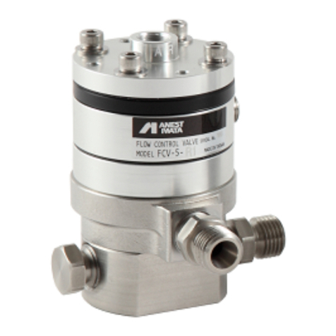
Anest Iwata FCV-3 User manual

重要仕様
最高使用圧力 液体 : 2.5MPa エア : 0.6MPa
使用温度範囲 雰囲気温度5℃〜40℃ 流体温度5℃〜43℃(液体、気体)
フローコントロールバルブ
FCV−3 /3N
この取扱説明書に示された警告事項および注意事項は必ず守ってください。
使用時に不用意に塗料が噴出したり、有機溶剤の吸引により重大な身体上の障害を起こすことがあります。
あ印付きの下記マークは、安全上、特に重要な項目ですので、必ずお守りください。
警告内容を怠った場合、人が死亡又は重傷を負う可能性が想定されることを示します。
注意内容を怠った場合、人が傷害を負う可能性、または物的損害の発生する可能性が想定され
ることを示します。
この記号は、機械の性能や機能を十分に発揮してお使いいただくために守っていただきたい内容
を示しています。尚、本取扱説明書で示す安全事項は、必要最低限のものであります。
国や自治体の消防、電気、安全関連の法規、規則又、それぞれの企業や事業所で規則、規定と
して守るべき事項に従ってください。
1.仕様
形式 接液部材質 圧力調整範囲
MPa
最大流量
L/min
最大1次圧力
MPa ねじ仕様 接続
エアチューブ 質量 g
FCV−3 アルミニウム・ステンレス 0〜0.6 2.0 2.5 IN:G3/8B
OUT:Rc1/4 φ6×φ4 550
FCV−3N ステンレス 720
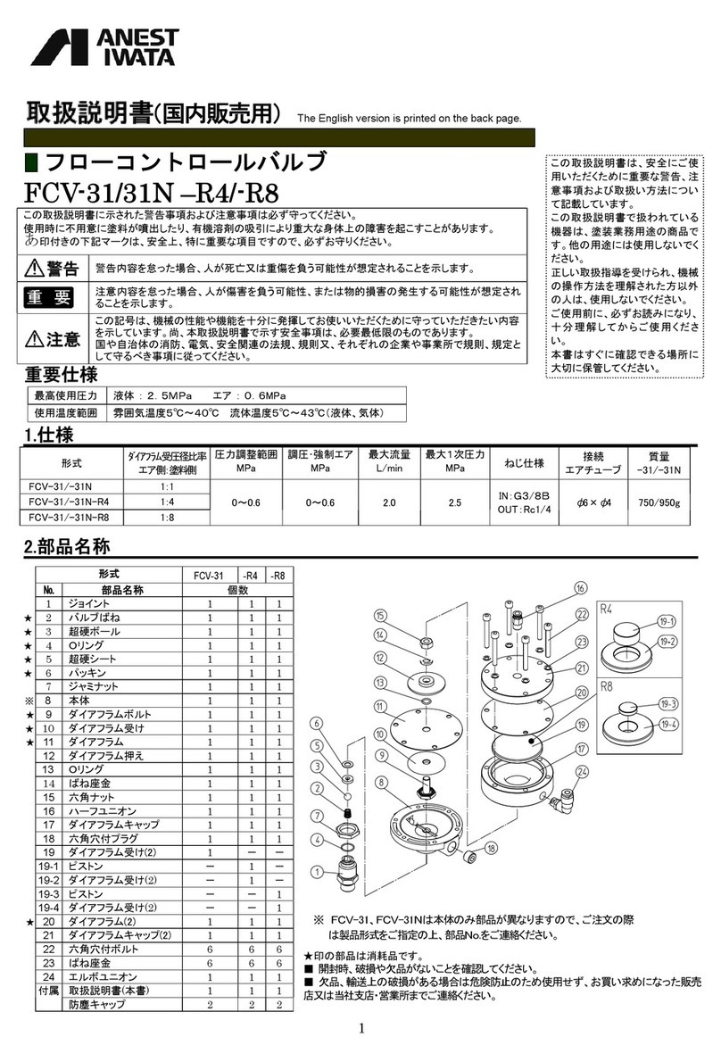
2.部品名称
※ FCV-3、FCV-3Nは本体のみ部品が異なりますので、ご注文の際
は製品形式をご指定の上、部品No.をご連絡ください。
■開封時、破損や欠品がないことを確認してください。
■欠品、輸送上の破損がある場合は危険防止のため使用せず、お買
い求めになった販売店または当社支店・営業所までご連絡くださ
い。
NO 部品名称 個数 NO 部品名称 個数
1ジョイント 1 13 Oリング 1
★
2バルブバネ 1 14 ばね座金 1
★
3超硬ボール 1 15 六角ナット 1
★
4Oリング 1 16 六角穴付ボルト 1
★
5超硬シート 1 17 ダイアフラムキャップ 1
★
6パッキン 1 18 六角穴付プラグ 1
7ジャミナット 1 19 ハーフユニオン 1
※
8本体 1 (付属品)
★
9ダイアフラムボルト 1 防塵キャップ 2
★
10 ダイアフラム受け 1 取扱説明書 1
★
11 ダイアフラム
12 ダイアフラム押え ★印の部品は消耗品です。
この取扱説明書は、安全にご使
用いただくために重要な警告、注
意事項および取扱い方法につい
て記載しています。
この取扱説明書で扱われている
機器は、塗装業務用途の商品で
す。他の用途には使用しないでく
ださい。
正しい取扱指導を受けられ、機械
の操作方法を理解された方以外
の人は、使用しないでください。
ご使用前に、必ずお読みになり、
十分 理解 してから ご使用く ださ
い。
本書はすぐに確認できる場所に
大切に保管してください。
(国内販売用) The English version is printed on the back page.

3.安全にご使用いただくための警告事項
人体保護
・作業中は、眼鏡、マスクおよび手袋などの保護具をかならず着用し、換気の良い
場所で使用してください。塗料や溶剤が目に入ったり、吸い込む危険性があります。
作業中、身体に異常を感じたら、ただちに医師による治療を受けてください。
機器誤用
・使用する際は、各部の取付け、調整が適当かどうか確認後操作してください。
・絶対に人や動物に向けてスプレーしないでください。
目や皮膚の炎症、人体への危険があります。
・洗浄、分解、保守作業をする前には必ず塗料の圧力を0MPaにしてください。
圧力が残っていますと、誤動作、洗浄液の飛散により人体に危険があります。
・塗料ホース、ポンプへの接続は、漏れや緩みがないように確実に接続してくだ
さい。
作業中塗料ホース等が抜け、塗料等の飛び跳ねによる傷害等重大な身体上の
危険があります。
ケガをした場合、ケガの大小にかかわらず、ただちに医師による治療を受けて
ください。
・最大1次圧力以下で必ず使用してください。
最大1次圧力以上で使用すると、塗料減圧弁が破損し、非常に危険です。
その他
・食品用や化学薬品用には使用しないでください。
塗料通路内部の腐食による事故や異物混入による健康障害の可能性があります。
・製品の改造は絶対にしないでください。
・部品を交換する場合は、当社純正部品を必ず使用してください。
十分な性能が発揮できないばかりか、故障の原因となります。
・FCV-3の場合、次のハロゲン化炭化水素系溶剤は、使用しないでください。
・FCV-3Nの場合、次のハロゲン化炭化水素系溶剤が、FCV-3Nにかからないようにしてください。
塩化メチル、塩化エチル、ジクロルメタン、1.2-ジクロルエタン、四塩化炭素、トリクロルエチレン、1.1.1-トリクロルエタン
化学反応により、アルミニウム部品にクラック、溶解が発生します。
(特殊な塗料や溶剤などは十分適合性を検討した上でご使用ください。適合性検討のための材質リストを提出する用意があります。)
4.接続方法及び操作方法
・吐出ネジ部(Rc1/4)にジョイント等を接続する際は、ネジ部に中強度接着剤又はテープシール等を巻き液漏れが発生しないようにしてください。
・塗料にはゴミ、異物などの混入がないよう注意してください。
異物が混入した塗料を使用するとシート漏れを起こし、吐出量が不安定になることがあります。
・塗料供給圧力はオペレートエア圧力よりも0.05MPa以上高くなるよう設定してください。
塗料供給圧力がオペレートエア圧力よりも低いと、吐出量が不安定になります。
接続例 手順-1 塗料供給口・吐出口に塗料ホースを確実
に取付けます。
手順-2 エア減圧弁からのエアを通したエア
チューブ(φ6×φ4)を接続します。
操作方法 エア減圧弁の圧力を上げると塗料2次圧力を高く
設定できます。
エア減圧弁の圧力を下げ、2次圧力を逃がす
と、2次圧力を低く設定できます。

5.分解と組立
・分解と組立はFCV-3でご説明します。FCV-3Nとの違いは部品No.8の本体の違いのみです。
・超硬ボール、超硬シートを分解した時は、摩耗やキズの有無を必ず確認してください。
摩耗やキズがある場合は、そのまま使用せず、新しい部品に交換してください。
5−1.分解
手順-1 六角穴付ボルトを外し、ダイアフラムキャップ、ダイアフラム部を
外します。
手順-2 ジャミナットを緩めジョイントを外し、バルブばね、超硬ボ
ール、超硬シート、パッキンを外します。
手順-3 ダイアフラムボルトの六角部を固定し、六角ナットを外し、ば
ね座金、ダイアフラム押え、Oリング、ダイアフラム、ダイアフラム
受けを外します。
手順-4 ジョイントに組込まれているOリングにキズ、変形等が見ら
れた場合、ジョイントよりOリングを外します。
5−2.組立
・超硬シートは、テーパー側に超硬ボールが組まれるよう本体に取付けてください。その際、パッキンを入れ忘れないように注意してください。
正しく組み立てられない場合、シート洩れによる圧力計の針上りが発生し十分な性能が発揮できません。
・ジョイントを取付ける場合、締付トルクに注意してください。
強く締め付け過ぎると本体が破損する場合があります。
ジョイント締付トルク 14.7N・m{150kgf・cm}
・ジョイントを取付ける際、超硬ボールがシートからズレないよう注意してください。
手順-1 各部にキズ、異物の付着がないか、確認します。
手順-2 ダイアフラムボルトにダイアフラム受け、ダイアフラム、Oリング、
ダイアフラム押え、ばね座金を取付け六角ナットを
締込みます。
六角ナット締付トルク 9.8N・m
{100kgf・cm}
手順-3 手順2でセットしたダイアフラム部、ダイアフラムキャップを
本体にのせ、六角穴付ボルトを対角線上に均等に
締め付けます。
手順-4 ジョイントにOリングを取り付けます。
手順-5 本体に、パッキン、超硬シートを組込みます。
手順-6 ジョイントにバルブバネ、超硬ボールを組込んだ後、本体
にジョイントを取付けます。
ジョイント締付トルク 14.7N・m
{150kgf・cm}
手順7 ジャミナットにて固定します

6.故障の原因と対策
☆印の処置は、お買いあげの販売店又はお近くの当社支店、営業所にご依頼ください。
正しい処置が行われない場合、十分な性能が発揮できなくなります。
現 象 原 因 対 策
2次圧力が上がりすぎる。 1.シートの当たり不良、ゴミ 1.再組立、洗浄
2.シートの摩耗、キズ 2.交換 超硬シート(NO.5)
3.ボールの摩耗、キズ
4.パッキンのキズ
3.交換 超硬ボール(NO.3)
4.交換 パッキン(NO.6)
外部に塗料が漏れる 1.ジョイント(NO.1)の緩み 1.締め増し
2.六角穴付ボルト(NO.16)の緩み 2.締め増し
3.六角ナット(NO.15)の緩み 3.締め増し
4.ダイアフラム(NO.11)の破損 4.交換 ☆
5.Oリング(NO.4)の破損 5.交換 Oリング(NO.4)
2次圧力が上がらない 1.一次圧力が低い 1.一次側圧力を上げる
圧力が安定しない 1.バルブバネ(NO.2)の破損 1.交換 バルブバネ(NO.2)
表中のNOは、1頁の部品表の部品NOを示します。
7.保証と修理サービス
・保証期間は、お買いあげの日から6ヶ月です。
・万一、故障の場合は、お買いあげの販売店又は当社支店・営業所にご連絡ください。
保証期間中は、無償修理いたします。
・無償保証を受けるための条件および手続き
本保証書をご提示の上、お買いあげの販売店、または当社支店・営業所・サービス会社にご依頼ください。
本保証書は日本国内においてのみ有効です。Thiswarrantyisvalidonlyinjapan
※本製品の故障または不具合に伴う生産補償、営業補償など二次損失に対する補償は致しません
ので、ご了承願います。
・次の場合は保証期間内でもお客様のご負担(有償)になります。
・取扱説明書の注意事項を守られなかったことによる故障および損傷
・お客様の取扱上の不注意による故障および損傷
・消耗品の交換・修理
・天災、地変、火災、地震、水害、塩害、落雷、公害などによる故障および損傷
・純正部品以外の部品が使用されている場合
・指定の修理店以外による修理がなされている場合
・製品に関するお問い合わせ、ご意見・ご希望などございましたら、当社お客様相談室までご連絡ください。
各種お問い合わせ先は変更する場合がございますので、最新のお問い合わせ先につきましては
当社ホームページをご覧ください。 アネスト岩田ホームページ http://www.anest-iwata.co.jp
〒223-8501 横浜市港北区新吉田町3176 取説No.1579−04
コードNo.04756412

− 1 −
Flow Control Valve
Be sure to observe warnings and cautions in this instruction manual.
If not, it can cause paint ejection and serious bodily injury by drawing organic solvent.
Be sure to observe following marked items which are especially important.
Indicates a potentially hazardous situation which, if not avoided, may result in serious injury or loss of life.
Indicates a potentially hazardous situation which, if not avoided, may result in minor or moderate injury or
property damage.
Indicates notes which we ask you to observe. The safety precautions in this instruction manual are the
minimum necessary conditions. Follow national and local regulations regarding fire prevention, electricity
and safety as well as your own company regulations.
Important specifications
Max. Working Pressure Fluid/ IN ; 2.5MPa / 25bar / 360PSI Fluid/ OUT ; 0.6MPa / 6bar / 87PSI Adj. Air ; 0.6MPa / 6bar / 87PSI
Max. Temperature Atmosphere ; 5℃〜40℃Fluid / Air ; 5℃〜43℃
Main specifications
Model Material of
wet section
Pressure range
(secondary)
MPa (bar / PSI)
Max. primary
pressure
MPa (bar / PSI)
Max. air
pressure
MPa (bar / PSI)
Max. Flow
L/min (cfm)
Fluid & Air
connection
Mass
g (lbs)
FCV
-
3
Aluminium
0 ~ 0.6
(0 ~6 / 0 ~87)
2.5
(25 / 360)
0.6
(6 / 87)
2.0
( 0.07 )
Fluid inlet G3/8
Fluid outlet Rc1/4
Air tubeφ6xφ4
550 (1.2)
FCV-3N Stainless steel 720 (1.6)
How to connect and operate
When connecting joints to exhaust thread section(Fluid outlet Rc1/4), apply median strength adhesive to thread section
or wind sealing tape around thread section to prevent liquid from leaking.
Pay attention that paint does not include dirt and foreign matter.
Using paint containing foreign matter can cause leakage from seated section and unstable fluid output.
Set so that primary side supply fluid pressure is higher than operating air pressure by over 0.05 Mpa(0.5bar/7.3PSI).
If primary side supply fluid pressure is lower than operating air pressure, fluid output will become unstable.
This Anest-iwata Flow Control Valve complies to ATEX
regulations 94/9/EC,
Protection level :
Ⅱ2 G X,Suitable for use in Zones 1 and 2.
X marking :
Any static electricity discharge from the flow control
valve is to be diverted to the grounded by connecting
to grounded pump or grounded fluid pipelines or
grounded metal bracket as stipulated.
This manual contains IMPORTANT WARNINGS and INSTRUCTIONS.
Equipment in this manual is exclusively for painting purposes.
Do not use for other purposes.
The operator shall be fully conversant with the requirements stated in this
instruction manual including important warnings, cautions and operation
and correct handling.
Read and understand the instruction manual, before use and retain for
reference.
FCV
-
3
・
FCV
-
3N
INSTRUCTION MANUAL

− 2 −
Connecting
example Job-1 Securely connect fluid hose to fluid inlet and
outlet.
Job-2 Connect air tube(φ6×φ4)coming from air
regulator
How to operate If you increase air pressure at air regulator, secondary
side fluid pressure will increase.
If you decrease air pressure at air regulator,
secondary side fluid pressure will decrease.
Safety precautions
Fire and explosion
1. Spark and open flames are strictly prohibited.
Paints can be highly flammable and can cause fire.
Avoid any ignition sources such as smoking, open flames, electrical goods, etc.
2. In case of FCV-3, never use the following HALGOGENATED HYDROCARBON SOLVENTS.
In case of FCV-3N, pay attention that its exterior does not come into contact with the
following halogenated hydrocarbon solvents.
which can cause cracks or dissolution on paint regulator body (aluminum) by chemical reaction.
・unsuitable solvents:methyl chloride, dichloromethane, 1.2-dichloroethane,carbon tetrachloride,
trichloroethylene, 1.1.1-trichloroethane
(Be sure that all fluids and solvents are compatible with paint regulator parts.
We are ready to supply a material list used in the product)
3. Securely ground flow control valve by connecting to grounded pump、grounded fluid pipelines or grounded metal bracket.
Ground parts :Less than 1MΩ. Check the earth stability periodically.
If not, insufficient grounding can cause fire and explosion due to static electric sparking.
Wrong operation of equipment
1. Before operation, confirm that each section is properly fitted and adjusted.
Installthepressurereliefvalveinconnected pipingroutetoletthepaintspressurereliefintheemergency.
2. Never spray toward people or animal.
If done, it can cause inflammation of eyes and skin or bodily injury.
3. Never exceed maximum operating pressure and maximum operating Temperature.
In theairsupply line,controlproperpressurebysettinguptheairpressuregauge.
4. Securely connect it to fluid hose and pump to avoid leakage and looseness.
Ifnot,hazardoushosemovementandpaintejectioncancauseseverebodilyinjury.
Ifyouareinjured,seeadoctorimmediately withoutregardtothedegreeofinjury.
5. Be sure to use at lower than max. primary pressure and max air pressure.
Use athigherthanmax.primary pressureand max. airpressurecancausedamage whichis verydangerous.
6. Be sure to use fluid hose which withstand Max. primary pressure working pressure 2.5MPa.
Whenthedeadlineoftheliquidbythecontactof theballand theseatbecomesdefective,thereisacasethesecondarypressure risestotheprimarypressure.
Pleaseremediesrepairreferringtothe paragraphoftheproblemandtheremedies.
Protection of human body
1.Use in a well-ventilated place to avoid serious injury caused by paints or solvents .
If not, poor ventilation can cause organic solvent poisoning and catch fire.
2. Be sure to reduce fluid pressure down to 0MPa before cleaning, disassembling or servicing.
If not, remaining pressure can cause bodily injury through ejection of cleaning liquid due to wrong operation.
3.During painting, , disassembling or servicing, be sure to wear protective cover such as glasses,
masks or gloves.
If not, cleaning liquid, etc., can cause inflammation of eyes and skin.
If you feel something wrong with eyes or skin, immediately see a doctor.
Other precautions
1.Never alter this equipment.
If done, it can cause insufficient performance and failure.
2.Never use it for foods or chemicals.
If done, it can cause accident by corrosion in paint passages and foreign matter can cause health problems.
3.If something goes wrong, immediately stop operation and find the cause. Do not use again until you have solved the problem.
4.Never use commercial or other parts instead of ANEST IWATA original spare parts.

− 3 −
Disassembling and assembling
・Whenever disassembling ball and seat of tungsten carbide, be sure to confirm that there is no wear or damage.
If there is any wear or damage, replace with new one.
■Disassembling
Job-1 Fully loosen handle set, a
nd remove bolt with hex.
hole, diaphragm cap, spring holder, adjusting
spring and diaphragm section.
Job-2 Loosen jam nut, and remove joint, valve spring,
ball, seat and packing.
Job-3 Fix hex. section of diaphragm bolt, and remove
hex. nut, spring washer, diaphragm stopper,
O ring, diaphragm and diaphragm holder.
Job-4 If O ring built into joint is damaged or deformed,
remove O ring from joint.
■Assembling
・Fit tungsten carbide seat to main body so that tungsten carbide ball can be fitted on tapered side. Do not forget to fit packing.
Faulty assembly can cause leakage from seated section, resulting in insufficient performance.
・Pay attention to tightening torque when fitting joint.
Too much tightening can damage main body.
Tightening torque of joint 14.7N•m {10.8 ft-lbf}
・When fitting joint, pay attention that tungsten carbide ball does not slip out of the seat.
Job-1
Check for damage and foreign matter
on each
section.
Job-2
Fit diaphragm holder, diaphragm, O ring,
diaphragm holder and spring washer into
diaphragm bolt and tighten hex. nut.
Tightening torque of hex. nut 9.8N•m
{ 7.2 ft-lbf }
Job-3
Mount diaphragm section and diaphragm cap
on main body, and evenly tighten bolts with hex.
bolt diagonally.
Job-4 Fit O ring to joint.
Job-5
Fit packing and tungsten carbide seat to main
body.
Job-6
Fit valve spring and ball to joint, and then fit joint
to main body.
Tightening torque of joint 14.7N•m
{10.8 ft-lbf }
Job-7 Fix joint with jam nut.

− 4 −
Problems and remedies
Contact and ask the shop which sold it to you regarding ☆marked items.
Wrong remedies can cause insufficient performance.
Problems Causes Remedies
Secondary
pressure
rise
s
too
much.
1. Not properly seated, or foreign matter
2. Wear or damage on seat
3. Wear and damage on ball.
4. Damage to packing
1. Clean and assemble again.
2. Replace. tungsten carbide seat(No.5)
3. Replace. tungsten carbide ball(No.3)
4. Replace. packing(No.6)
Paint leaks outside. 1. Loose joint (No.1)
2. Loose bolt with hex. hole (No.16)
3. Loose nut(No.15)
4. Damage to diaphragm (No.11)
5. Damage to O ring(No.4)
1. Tighten.
2. Tighten.
3. Tighten.
4. Replace. ☆
5. Replace O ring(No.4).
Secondary pressure does not rise. 1. Low primary pressure. 1. Raise primary side pressure.
Pressure is unstable. 1. Damage to valve spring(No.2)1. Replace valve spring(No.2).
※The number in parentheses() shows the number of parts lists.
Parts list
No. Parts name Qty No. Parts name Qty
1 Joint 114 Spring washer 1
2 Valve spring 115 Hex. nut 1
★3 Ball 116 Bolt with hex. hole 6
★4Oring 117 Diaphragm cap 1
★5 Seat 118 Plug with hex. hole 1
★6 Packing 119 Half union 1
7 Jam nut 1 Accessories
※8 Main body 1Anti-dust cap
Instruction manual
2
19 Diaphragm bolt 1
★10 Diaphragm holder 1 ★marked parts are consumable
parts.★11 Diaphragm 1
12 Diaphragm stopper 1
13 Oring 1
※
As the only difference between FCV
-
3 and FCV
-
3N is main body,
specify ref. No., and part name when ordering parts.
■Never use commercial or other parts instead of ANEST IWATA original spare parts.
■When unpacking, confirm that there is no damage or shortage.
■If there is damage or shortage during transportation, do not use the equipment and contact the shop
which sold it to you.
No.1579-04
CodeNo.04756411
3176,Shinyoshida-Cho,Kohoku-Ku,Yokohama223-8501,Japan
This manual suits for next models
1
Table of contents
Other Anest Iwata Control Unit manuals
Popular Control Unit manuals by other brands

BRAHMA
BRAHMA E8 Series quick start guide

NXP Semiconductors
NXP Semiconductors TWR-56F8400 user manual

ELECTRONIC ASSEMBLY
ELECTRONIC ASSEMBLY DISPLAY VISIONS EA eDIP Series manual

Dataprobe
Dataprobe iBootBar Installation and operations

Friendess
Friendess BCL1501 user manual

Fisher
Fisher D4 instruction manual

Bosch
Bosch rexroth SB11 instruction manual

Pentair
Pentair FLECK 2850 SXT user guide

Panasonic
Panasonic CF-BAX04GU operating instructions

Bauerfeind
Bauerfeind Uniprox V08 instruction manual

Grundfos
Grundfos CIM 2 Series Installation and operating instructions

Voltdrive
Voltdrive voltguard portguard user manual