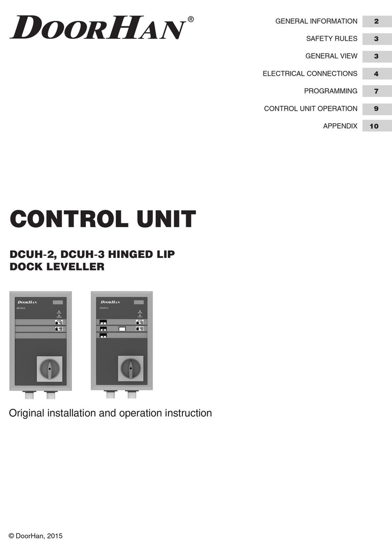
DoorHan DCUH-2 User manual

© DoorHan, 01.2020
Owner’s Manual
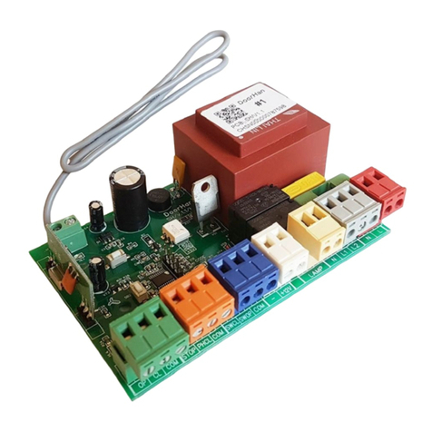
DCUH-2/3 Control
Unit for Electro-
Hydraulic Dock
Leveler with
Hinged Lip
General Information 2
Safety Rules 2
Design 3
Installation 4
Electrical Connections 5
Programming 8
Control Unit Operation 11
Troubleshooting 11
Appendix 12

2
DCUH-2, DCUH-3 control units operate electro-hydraulic
dock levelers with hinged lip of DLHH/DLHHI series.
The units are equipped with an uncontrolled movement
protection system, which is activated if the dock leveler
was halted in the event of a potential emergency or if pow-
er supply failed.
After all the necessary connections, the unit is ready for
operation.
1. GENERAL INFORMATION
GENERAL INFORMATION
Options DCUH-2 DCUH-3
Automatic return to stored position by pressing the P button
Supply voltage, 380-415 V / 50-60 Hz
External traffic light
Internal traffic light
Dock leveler lighting
Leveler locking when door is closed (interlock)
Door locking when leveler is open (interlock)
Connection of additional safety devices
Service indicator
Menu screen (LCD display)
Door control
Inflatable dock shelter control
Table 1.1. Control units options
Table 1.2. Control units specifications
Parameters Value
Supply voltage 380-415 V / 50-60 Hz
Control voltage 24 VDC
Max. power of the hydraulic station 1,5 kW
Operating temperature -20…+50 °С
Dimensions (W × H × D) 195 × 355 × 165 mm
Protection class IP54
Use the control unit only for its intended purpose, any
other use is prohibited.
The manufacturer assumes no liability for damage or
injury to persons or property which occur as a result of
failure to observe safety rules specified herein or incor-
rect use of the control panel.
Only trained personnel should install, operate or service
this equipment.
Correct operation of the control unit can only be guar-
anteed if the supply voltage complies with the specified
in the instructions.
Prior to first actuation of the control unit, make sure
that all electrical connections are securely fastened and
insulated, safety devices are installed and ready for use.
2. SAFETY RULES
WARNING!
Carefully follow all the instructions specified herein. Failure to do so could cause equipment damage and/or per-
sonal injury!

3
3. DESIGN
1. Menu screen (LCD display)
2. Service indicator
3. Power indicator
4. Dock leveler parking button (P)
5. Dock leveler RAISE button
6. Main power switch
7. Inflatable dock shelter control button
8. Door CLOSE button
9. Door STOP button
10. Door OPEN button
Fig. 3.1. Closed view
1
2
3
4
5
6
1. Main board
2. Control board
Fig. 3.2. Open view
1
2
DESIGN
1
2
3
4
5
6
7
8
9
10

4
Fig. 4.1. Control unit installation
Mount the control unit so the distance between control unit bottom and dock floor is approximately 1–1,5 m. Choose the
fasteners corresponding to the type of wall.
4. INSTALLATION
Anchor points
INSTALLATION

5
ELECTROMAGNETIC
VALVE COIL
EXTERNAL
TRAFFIC LIGHT
INTERNAL
TRAFFIC LIGHT
LIGHTING
DOCK SHELTER MOTOR
HYDRAULIC STATION
MOTOR PHOTOELECTRIC
END SWITCH
DOOR OPERATOR
OUT
X10
W
W
V
U
V
U
COM
OPEN
STOP
CLOSE
COM
OPEN
STOP
CLOSE
+24V
GND
IN 4
+24V
GND
IN 3
+24V
GND
IN 2
+24V
GND
IN 1
DIP
X11 X12
X14
X1
+24
123
ON
4
FU
X15X16X17X18X19
X22
X20X21
FU
FU
RED
M
M
~380 - 415 V
~380 - 415 V
0,55 kW
GREEN
RED
GREEN
L*
N*
N
PE
PE
PE
PE
L3
L2
L1
6,3 A
6,3 A
6,3 A
5. ELECTRICAL CONNECTIONS
WARNING!
Before performing electrical connection of the control unit disconnect all electric power and ensure it won’t be sup-
plied during the work.
Fig. 5.1. Electrical connections diagram
ELECTRICAL CONNECTIONS
SAFETY DEVICES CONNECTION
FU fuse 6,3 A / 250 V AC
220 V

6
ELECTROMAGNETIC
VALVE COIL
EXTERNAL
TRAFFIC LIGHT
INTERNAL
TRAFFIC LIGHT
LIGHTING
DOCK SHELTER MOTOR
HYDRAULIC STATION
MOTOR PHOTOELECTRIC
END SWITCH
DOOR OPERATOR
OUT
X10
W
W
V
U
V
U
COM
OPEN
STOP
CLOSE
COM
OPEN
STOP
CLOSE
+24V
GND
IN 4
+24V
GND
IN 3
+24V
GND
IN 2
+24V
GND
IN 1
DIP
X11 X12
X14
X1
+24
123
ON
4
FU
X15X16X17X18X19
X22
X20X21
FU
FU
RED
M
M
~380 - 415 V
~380 - 415 V
0,55 kW
GREEN
RED
GREEN
L*
N*
N
PE
PE
PE
PE
L3
L2
L1
6,3 A
6,3 A
6,3 A
ELECTRICAL CONNECTIONS
~380 - 415 V
PE
L3
L2
L1
W
V
U
X1
FU
FU
FU
L3
L2
L1
N N
N*
L2*
PE
PE
PE
PE
6,3 А
6,3 А
6,3 А
View А
Fig. 5.2.1. View A. Power supply connection
Fig. 5.2. 380–415 V mains connection

7
ELECTRICAL CONNECTIONS
СВЕТОФОР
ВНУТРЕННИЙ
ЛАМПА
ОСВЕЩЕНИЯ
TERMINALS
ON OPERATOR
CONTROL
BOARD
X10
COM
OPEN
STOP
CLOSE
COM
OPEN
STOP
CLOSE
+24V
GND
IN 4
+24V
GND
IN 3
X11
FU
X18X19X20X21
ЗК
И
ELECTROMAGNETIC
VALVE COIL
EXTERNAL
TRAFFIC LIGHT
INTERNAL
TRAFFIC LIGHT
LIGHTING
DOCK SHELTER MOTOR
HYDRAULIC STATION
MOTOR PHOTOELECTRIC
END SWITCH
DOOR OPERATOR
OUT
X10
W
W
V
U
V
U
COM
OPEN
STOP
CLOSE
COM
OPEN
STOP
CLOSE
+24V
GND
IN 4
+24V
GND
IN 3
+24V
GND
IN 2
+24V
GND
IN 1
DIP
X11 X12
X14
X1
+24
123
ON
4
FU
X15X16X17X18X19
X22
X20X21
FU
FU
ЗКЗК
M
M
~380 - 415 V
~380 - 415 V
0,55 kW
white
blue
blue
black
black
brown
brown
Fig. 5.3. Connection of lip inductive position sensor (part number: 1747-22)
Fig. 5.4. Connection of photoelectric end switch

8
6. PROGRAMMING
DIP switches are used to switch between the operating modes of the control unit board.
WARNING!
Prior to switching between the operating modes turn the power supply OFF.
When using the device for the first time make sure the DIP switches 1 and 2 are in correct position.
6.1. DIP SWITCHES
Table 6.1.1. DIP switches operation
DCUН-2 operating mode DCUН-3 operating mode
DIP 1 = Off DIP 1 = Off
DIP 2 = Off DIP 2 = On
DIP 3 is used to enter the advanced menu.
DIP 3 = Off (main menu)
DIP 3 = On (advanced menu)
DIP 3 is used to enter the advanced menu.
DIP 3 = Off (main menu)
DIP 3 = On (advanced menu)
DIP 4 is not used DIP 4 is not used
Menu screen shows dH2 Menu screen shows dH3
In DCUH-2 mode each operation of the door and dock leveler is displayed on the menu screen accordingly (see Ta-
ble 6.1.2).
PROGRAMMING
* Connection scheme refers to DoorHan operators of Shaft series only.
Fig. 5.5. Connection scheme of lip inductive position sensor for DCUH-2 control unit*
Shaft operator
control post
Lip inductive
position sensor
Shaft operator control board terminals
brown
white
black
bluered
COM OPEN STOP CLOSE
+24V

9
PROGRAMMING
In DCUH-3 mode each operation of the door and dock leveler is displayed on the menu screen accordingly (see Ta-
ble 6.1.3).
Table 6.1.2. LCD display indication in DCUH-2 mode
Dock equipment Menu screen message Operation
Dock leveler PUP Leveler rising
Pdn Leveler lowering
Table 6.1.3. LCD display indication in DCUH-3 mode
Dock equipment Menu screen message Operation
Door
GUP Door rising
Gdn Door lowering
GSt Door stopping
Dock leveler PUP Leveler rising
Pdn Leveler lowering
If it is time to perform maintenance, the operation indica-
tion is blocked, the SEr message is constantly displayed
on the menu screen and the service led is lit. In order to
remove a service tick enter the advanced programming
menu. The same applies to the faults indication: if a fail-
ure occurs during operation, EX message will be displayed
before the system is de-energized, where X is the fault
number. The number of the last fault may be viewed in the
advanced programming menu.
In order to enter the programming menu turn the main
power switch ON. Make sure the power indicator is lit, then
press and release the RAISE button. After that press the P
and RAISE buttons simultaneously and hold for 5 seconds.
Flashing UH message on the menu screen confirms you
have successfully entered the programming menu.
6.2. TO ENTER PROGRAMMING MENU
Message Setting option Description
1. UH
Parameter value 1–9 — 3–11 sec.
Default value — 7 sec.
Change of value by 1 equals 1 sec.
Time period in which hydro station motor stops during leveler
raising
2. UC
Parameter value 1–9 — 5–21 sec.
Default value — 13 sec.
Change of value by 1 equals 2 sec.
Leveler lowering time in auto parking mode
3. Hd
Parameter value 1–9 — 2,5–6,5 sec.
Default value — 4,5 sec.
Change of value by 1 equals 0,5 sec.
Leveler raising time at the last stage of parking
4. AF Parameter value 1–9 Operating threshold of the leveler stop function during leveler rais-
ing mode only
5. Ar (Y/n), default value — Y Activation of auto parking function
6. CXX (0–99) Cycles counter / 1000
7. SXX (0–99) Service counter
8. EXX (0–99)
Indication of the last equipment failure:
E00 — no equipment failures during the whole period of operation;
E01 — usage error;
E03 — short circuit in hydraulic station motor winding;
E04 — control board short circuit
9. rS(1) (Y/n), default value — n Reset of service mode
Table 6.2.1. Parameters of the DCUH-2 programming menu

10
Item 1 is available until the service mode is reset.
Items 1–6 refer to main programming menu while items
7–13 — to advanced programming menu.
Navigation through the menu is carried out by the RAISE and
P buttons. RAISE button is used to switch between the pa-
rameters, and P button changes the value of the parameter.
The device automatically exits the programming mode and
saves the changed values after setting the parameter of
the last menu item and pressing the RAISE button.
There are three variants of operation of dock leveler and
sectional door.
Variant 1. Dock leveler auto parking is OFF, door auto clos-
ing is OFF.
Set the following values for parameters 5 and 6 in pro-
gramming menu (see table 6.2.2):
choose n value for parameter 5;
choose n value for parameter 6.
Variant 2. Dock leveler auto parking is ON, door auto clos-
ing is OFF.
Set the following values for parameters 5 and 6 in pro-
gramming menu (see table 6.2.2):
choose n value for parameter 5;
choose Y value for parameter 6.
Variant 3. Dock leveler auto parking is ON, door auto clos-
ing is ON.
Set the following values for parameters 5 and 6 in pro-
gramming menu (see table 6.2.2):
choose Y value for parameter 5;
choose Y value for parameter 6.
6.3. TO EXIT THE PROGRAMMING MODE
6.4. PROGRAMMING OF DOCK LEVELER AND SECTIONAL DOOR OPERATION
PROGRAMMING
Table 6.2.2. Parameters of the DCUH-3 programming menu
Message Setting option Description
1. UH
Parameter value 1–9 — 3–11 sec.
Default value — 7 sec.
Change of value by 1 equals 1 sec.
Time period in which hydro station motor stops during leveler
raising
2. UC
Parameter value 1–9 — 5–21 sec.
Default value — 13 sec.
Change of value by 1 equals 2 sec.
Maximum leveler lowering time in auto parking mode
3. Hd
Parameter value 1–9 — 2,5–6,5 sec.
Default value — 4,5 sec.
Change of value by 1 equals 0,5 sec.
Leveler raising time at the last stage of parking
4. AF Parameter value 1–9 Operating threshold of the leveler stop function during leveler
raising mode only
5. dL (Y/n), default value — n Automatic closing of the door after the leveler is parked
6. Ar (Y/n), default value — Y Activation of auto parking function
7. CXX (0–99) Cycles counter / 1000
8. SXX (0–99) Service counter
9. EXX 0–99
Indication of the last equipment failure:
E00 — no equipment failures during the whole period of operation;
E01 — usage error;
E03 — short circuit in hydraulic station motor winding;
E04 — short circuit on control and display board
10. SL (Y/n), default value — Y Inflatable dock shelter operation
11.Sb
Parameter value 1–9 — 17–35 sec.
Default value — 25 sec.
Change of value by 1 equals 2 sec.
Deflating time of the dock shelter
12. Gd
Parameter value 1–9 — 2–18 sec.
Default value — 10 sec.
Change of value by 1 equals 2 sec.
Time of automatic closing of the door after the leveler is parked
13. rS (1) (Y/n), default value — n Reset of service mode
11
7. CONTROL UNIT OPERATION
7.1. TO RAISE THE LEVELER
1. Park the transport vehicle with an open body in front
of the leveler so that it is positioned squarely against
dock bumpers.
2. Chock the vehicle wheels to prevent accidental depar-
ture.
3. Turn the main power switch ON to operate the leveler.
4. Make sure the power led on the control unit is lit, then
press the RAISE button.
5. Keep the RAISE button pressed until the leveler deck
is fully raised and the lip is extended. Then release the
button and wait till the leveler deck lowers on the ve-
hicle bed. The lip should have a minimum of 100 mm
overlap on the vehicle bed surface.
WARNING!
Keep the main power switch ON till the leveler stops working and returns to the stored position!
Should any emergency arise halt the dock leveler in place by turning the main power switch OFF.
When loading or unloading is finished resume the
stored position of the dock leveler by pressing and
holding the RAISE button until the lip folds vertically
downwards. Then release the RAISE button and wait
till the leveler returns to the stored position. After that
turn the main power switch 0FF.
Auto parking of the leveler:
Press the P button briefly. Wait till the dock leveler re-
sumes the stored position. After that turn the main power
switch 0FF.
7.2. TO STORE THE LEVELER
7.3. EMERGENCY STOP
8. TROUBLESHOOTING
WARNING!
To resume operations turn the main power switch ON and press RAISE button shortly.
Symptom Possible cause Solution
Leveler does not
rise (pump does not
rotate)
No supply voltage Check the electrical wires
and the voltage in the socket
Faulty power switch Replace main power switch
Blown fuse Replace fuse (FU)
Faulty contactor Replace main board
No power to the contactor coil Replace main board
No jumper on terminals
for safety devices
Set the jumpers to
Х15, Х16, Х17, Х18
Lip inductive position sensor or photoelectric sensor is
open Check both sensors
Faulty control buttons Replace control board
Leveler does not
rise (pump rotates) Incorrect phasing Swap any two phases in the control unit
Leveler does not lower No power to the electromagnetic valve coil
Check wiring from control unit to coil.
Check coil voltage (24 VDC)
Replace main board
Faulty electromagnetic valve coil or valve Replace coil or valve
Table 8.1. Possible faults, their causes and solutions
CONTROL UNIT OPERATION

12
Fig. 1. Control unit design
* Cables are connected to hydraulic stations and supplied with the dock levelers.
Table 2. Connecting cables to the dock leveler control unit*
Table 1. Spare parts for the control unit
# Part name Part number
1DCUH-2 main board PCB_DCUH2-M/V.1.1
DCUH-3 main board PCB_DCUH3-M/V.1.1
2DCUH-2 control board PCB_DCUH2-BT/V.1.0
DCUH-3 control board PCB_DCUH3-BT/V.1.0
3 Switch assembly DCU007
3
2
1
APPENDIX. RECOMMENDED SPARE PARTS
# Part name Length Part number
- Connecting cable for DCUH-1/2/3 control units 7 m DKHL02-2
- Connecting cable for DCUH-1/2/3 control units 10,5 m DKHL02-3
APPENDIX

NOTES
13

14
NOTES

NOTES
15

We very much appreciate that you have chosen
the product manufactured by our company and
believe that you will be satisfied with its quality.
For information on purchasing, distribution and
servicing contact DoorHan central office at:
120 Novaya street, Akulovo village,
Odintsovo district, Moscow region,
143002, Russia
Phone: +7 495 933-24-00
E-mail: [email protected]
www.doorhan.com
NO. 5188, West BaoDai Road Xukou Town,
Suzhou, Jiangsu, China
Phone: +86-512-66-31-61-11
E-mail: [email protected]
www.doorhan.com
This manual suits for next models
1
Table of contents
Other DoorHan Control Unit manuals

DoorHan
DoorHan DCUH-1 User manual

DoorHan
DoorHan GC2 Operating instructions

DoorHan
DoorHan DCUH-1 User manual

DoorHan
DoorHan PE200B User manual

DoorHan
DoorHan DCUH-1 User manual

DoorHan
DoorHan DCUT-1 User manual

DoorHan
DoorHan GC4 Operating instructions

DoorHan
DoorHan PCB-SH Installation manual

DoorHan
DoorHan CV01 User manual

DoorHan
DoorHan DCUT-1 User manual