Instillation Instructions
(all
electrical & plumbing should be done in accordance to all local codes)
Your new Iron
Blaster™
allows for simple installation and
start up. Installation diagrams are provided to
assist
you.
Use of these diagrams and the
following
procedures will
ensure that
the system is properly installed.
Follow all state and local plumbing and electrical codes!
•
Do not use
vaseline,
oils, other hydrocarbon lubricants
or spray silicone anywhere. A silicon lubricant may be used
on black o‑rings but is not
necessary
.
avoid
any
type
of lubricants, including silicone, on red or clear lip
seals.
•
Do not use pipe dope or other
sealants
on threads.
Only
teflon tape may be used on threads. Teflon
tape is not
necessary on the nut connection or caps because of radial
o‑ring
seals.
•The pipe
size
for the drain line
should
be a
minimum
of 3/4”.
Backwash
flow
rates
in
excess
of 10 gpm
or
length
in
excess
of 20’ require 1” drain
line.
1. Place the filter where you want to install it, making sure
it is on a clean, level and firm
base.
2. Do all
necessary
plumbing
(Install check valve on inlet
to filter
,
inlet to inlet, outlet to outlet and drain line to
drain).
The control valve, fittings and/or bypass are
designed to accommodate minor
plumbing
misalignments but are not designed
to support the weight
of a system or
the
plumbing.
3. When assembling the installation
fitting
package (inlet
and outlet), connect the
fitting
to the
plumbing
system first
and then attach the nut, split ring and o‑ring. Heat from
solder
- ing or solvent cements may damage the nut,
split ring or o‑ring. Solder joints should be cool and
solvent cements should be set before installing the nut,
split ring and
o
‑
ring.
Avoid
getting
primer and solvent cement on any part of
the o‑rings, split rings, bypass valve or control
valve.
4.
a
jumper ground wire should be installed between the
inlet and outlet pipe whenever the metallic continuity
of a water distribution piping system is interrupted.
Install grounding strap on metal pipes.
5. The drain connection may be made using either 5/8” poly-
tube with nut & insert (see page 23, figure 17) or a
3/4”
female
adapter
.
If soldering, joints near the drain must be
done prior to connecting the drain line flow control fitting.
Leave at least 6” between the drain line control
fitting
and
solder joints when soldering pipes that are connected on
the drain line control fitting. Failure to do this could
cause
interior damage to the drain line flow control fitting.
6
.
When installing a fi
lt
er
system
it
is
common
t
o
provide
filtered
water
to
some fixtures such as the kitchen cold faucet.
This
is typically done as a
matter
of personal preference. In
rare
occasions it has been
noted
that the customer may
experi
-
enc some air in the filtered water line on the
morning
after
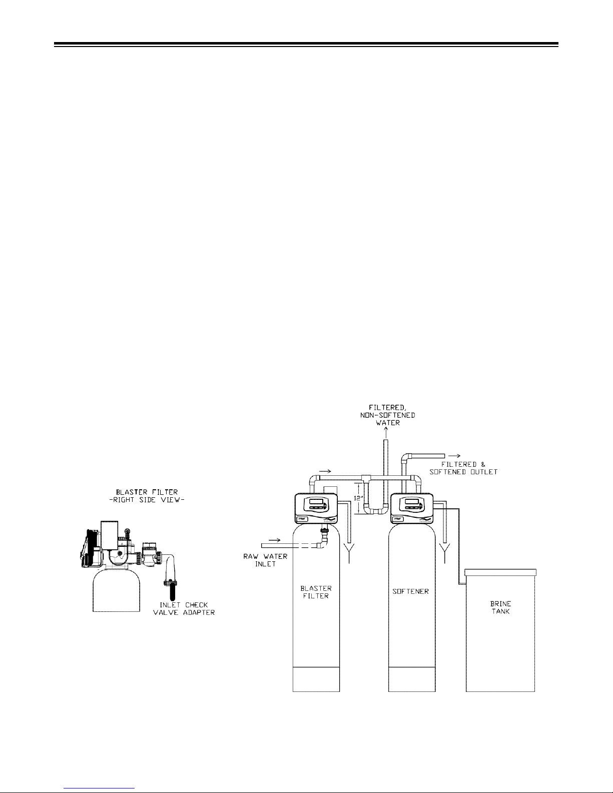
regeneration. It has proven to be beneficial to plumb the
line for filtered‑only water fixture in a downward direction
before the inlet to the softener (12 inches recommended),
then
make a reverse
turn
and
go upward toward
the
fixture.
Understanding that air always rises to the highest point in
a water system.
When installing an Iron
Blaster™
Filter
system
it is
common
to provide filtered only water to
some
fixtures
such
as the kitchen
cold
faucet.
This is typically
done
as a
matter
of
personal preference.
On rare
occasions,
the
customer
may
experience some
air in
the
filtered water line the morning after
regeneration.
It has
proven beneficial
to plumb the line for the filtered only water fixture in
a
downward direction
from the inlet of the
softener
(12
inches recommended),
then make a
reverse
turn and go
upward toward the
fixture. Any
accumulated
air always rises to the
highest
point in a water
system
and
cannot
naturally flow
downwar
d.