ANHUA ToughLift ML-10 User manual

T
ough
L
ift
®
MATERIAL LIFTS
ML-10/ML-15/ML-20/ML-25
MAINTENANCE MANUAL
(Serial number range: From SA700100)

1ToughLift®Material Lifts Maintenance Manual
Contents
1.1 Introduction 3
1.2 Characteristics & description 4
1.3 Intended use 5
1.4 Modications 5
1.5 Terminology 6
1.6 Technical data 8
7.1 Safety & instructions 30
7.2 How to remove the chassis 32
7.3 How to disassemble the mast 33
7.4 How to release the mast safety brake when servicing the mast 36
7.5 How to assemble the mast 37
7.6 How to replace the lifting cable using the Cable Coupler accessory 39
7.7 How to replace an inner lifting pulley wheel with the mast assembled 41
7.8 How to disassemble the winch 43
7.9 How to assemble the winch 44
Section 1 - Description & Specication Page
Section 2 – Safety During Maintenance 10
Section 3 – Service Engineer Attributes 12
Section 4 – Competent Person for Thorough Examination Attributes 13
Section 5 – Periodical Maintenance & Checks 14
Section 6 – Troubleshooting 29
Section 7 – Repair Procedures
Section 8 – Exploded Drawings & Parts List 48
Section 9 – Machine Labelling & Manuals 66
Section 10 – Storage 73
Section 11 – Disposal 73
Appendix - Schedule 1 - Information to be contained in a report of a
thorough examination
(The Lifting Operations and Lifting Equipment Regulations 1998 -
Regulation 10 (1)).
(UK only, regulations in other countries vary).
75
This page has been left blank intentionally.

2 3ToughLift®Material Lifts Maintenance ManualToughLift®Material Lifts Maintenance Manual
1.1 Introduction
Section 1 – Description & Specication
This Maintenance Manual provides detailed scheduled maintenance information, troubleshooting, repair
procedures, and exploded drawings with parts lists, to enable a qualied maintenance engineer or
technician to undertake work on ToughLift®Material Lifts and accessories as follows:
Maintenance engineers and technicians should read, understand, and adhere to all the information
contained in the ToughLift®Material Lifts Instruction Handbook and in this Maintenance Manual before
undertaking any maintenance work on a ToughLift®Material Lift or accessory.
Basic mechanical skills are required to perform most procedures outlined in this Maintenance Manual.
However, several procedures require specialised skills, tools, lifting equipment, and a suitably equipped
workshop.
Additional copies of this Maintenance Manual and the ToughLift®Material Lifts Instruction Handbook
may also be obtained from the manufacturer; please see the contact details on the back cover.
The information contained in this Maintenance Manual is based on the latest product information at the
time of publication. The manufacturer operates a policy of continuous product improvement and
reserves the right to make product changes at any time without notice.
Model/Accessory Product Code
ML-10 600010
ML-15 600015
ML-20 600020
ML-25 600025
Standard Forks (standard on all models) 640000
Stabiliser Set (standard on ML-20 & ML-25) 620000
Load Platform 670000
Pipe Cradle 610043
Extension Forks 660000
Rough Terrain Wheel Kit 680000
Boom 650000
This page has been left blank intentionally.

4 5ToughLift®Material Lifts Maintenance ManualToughLift®Material Lifts Maintenance Manual
1.3 Intended use
1.4 Modications
Section 1 – Description & Specication /continued
The ToughLift®Material Lifts have been designed to comply with the safety requirements of the
European Machinery Directive 2006/42/EC and the Supply of Machinery (Safety) Regulations 2008 (UK).
The ToughLift®Material Lifts are designed solely for the purpose of lifting materials to enable work to
be undertaken at height. The ToughLift®Material Lifts are designed for indoor and outdoor use, but not
in strong or gusting winds, and must be used on level ground which is able to support the weight of the
machine, any accessory tted, and the load being lifted.
The ToughLift®Material Lifts are designed for a multitude of tasks including building and construction,
particularly t and strip out, shop tting, general maintenance, and facilities management. The machines
are used on construction sites and in hospitals, schools, airports, shopping centres, retail outlets,
transport environments, factories, and oces.
WARNING
The operator must obtain the guidance and written approval from the manufacturer in the event of any
special working methods or conditions which are outside those specied in this section.
No modications shall be made to any ToughLift®Material Lift or accessory unless the manufacturer
has given full written approval. If in doubt, please contact the manufacturer for advice:
Shenzhen Anhua Limited
A1202-1 Tianan Cyber Park
No. 441 Huang Ge Road
Longgang
Shenzhen 518116
China
+44 20 7173 9777
Section 1 – Description & Specication /continued
1.2 Characteristics & description
The ToughLift®Material Lifts include the following features as standard:
Heavy-duty construction.
Quick and simple setup; no tools required.
Portable compact design for easy transport and storage.
Anodised lightweight aluminium telescoping mast.
Mast safety braking system holds the carriage and lifting column(s) in position if the cable
becomes loose or breaks.
Hard-wearing aluminium mast pulley wheels with sealed bearings.
Extra wide aluminium rst pulley wheel improves laying of the cable on the winch drum.
Cable guard tted where the operator stands behind the mast in case a cable should break.
Comprehensive main operational and safety decal on the front face of the cable guard.
Carriage lock operates whether Standard Forks are inserted up or down, and with the Boom
inserted in the top of the carriage.
Heavy-duty castors with non-marking tyres.
Braked swivel castors with foot operated brake on side and bolted foot-operated straight-line lock
to aid loading for transport or moving in a straight line on site.
Long loading wheels/handles shaft so that the mast is horizontal when the machine is laid back
for transport.
Loading wheels with sealed bearings rotate with ease.
Hoisting and winching anchor.
Bushed joints across the machine.
E-coated and then powder coated steel fabrications tted with silicone rubber end caps.
Robust waterproof document holder with A5 Instruction Handbook.
QR code decal to scan to open the Instruction Handbook on a smartphone.
Easy to wind dual handled manual winch with brake to hold the load in place.
Standard Forks can be tted up or down in the carriage on the mast.
Spirit level to aid the operator to level the chassis before raising the mast.
The following accessories are also available for use with ToughLift®Material Lifts:
Stabiliser Set (standard on ML-20 & ML-25)
Pipe Cradle
Load Platform
Extension Forks
Rough Terrain Wheel Kit
Boom

6 7ToughLift®Material Lifts Maintenance ManualToughLift®Material Lifts Maintenance Manual
15 Document holder
16 Braked swivel castor
17 Chassis
18 Front leg
19 Front leg retaining pin
20 Front leg swivel castor
21 Stabiliser (standard on ML-20 and ML-25/
optional on ML-10 and ML-15)
22 Stabiliser brace latch plates
23 Stabiliser brace
24 Stabiliser swivel castor
25 Rough Terrain Wheel Kit support locator
26 Spirit level
1.5 Terminology/continued
Section 1 – Description & Specication/continued
1.5 Terminology
Section 1 – Description & Specication/continued
The machine below is an ML-20. Boom accessory.
Rough Terrain Wheel Kit accessory.
Extension Forks accessory.
Load Platform accessory.
Pipe Cradle accessory.
2
3
20 18 19
4
5
24 21
6
1
7
8
9
10
11
12
13
14
16
15
17 252223 26
32
1 Mast
2 Carriage lock
3 Carriage
4 Standard Forks/Boom retaining pin
5 Standard Forks
6 Hoisting/winching anchor
7 Cable guard
8 Main operational & safety decal
9 Cable
10 Winch
11 Winch handle
12 Push & steer handle
13 Loading wheel
14 Mast brace
27 Standard Forks/Boom retaining pin
28 Lifting shackle
31 Rough Terrain Wheel Kit
33 Extension Forks
34 Extension fork retaining pin
32 Load Platform
35 Pipe Cradle
29 Shackle retaining pin
30 Lifting hook (may be removed if required)
35
27
29
28
30
31
33
34

8 9ToughLift®Material Lifts Maintenance ManualToughLift®Material Lifts Maintenance Manual
Section 1 – Description & Specication/continued Section 1 – Description & Specication/continued
1.6 Technical data 1.6 Technical data/continued
MODELS
ML-10 ML-15 ML-20 ML-25
LOAD CAPACITY, WEIGHT, & OPERATING ANGLE
Load capacity Refer to the Load Capacity Table on the page opposite for
load capacities at different load centres.
Machine weight (1) 129kg 153kg 190kg 214kg
Maximum allowable chassis
inclination 0° 0° 0° 0°
DIMENSIONS
Working Heights
With Standard Forks down 2.97m 4.46m 5.94m 7.42m
With Standard Forks up 3.49m 4.98m 6.46m 7.94m
With Load Platform forks down (2) 2.97m 4.46m 5.94m 7.42m
With Load Platform forks up (2) 3.49m 4.98m 6.46m 7.94m
With Boom (3) 3.28m 4.76m 6.25m 7.42m
Other Dimensions
Width with stabilisers deployed N/A N/A 1.84m 1.84m
Length with front legs deployed 1.51m 1.88m 2.06m 2.06m
Stowed width 0.81m 0.81m 0.81m 0.81m
Stowed length 0.76m 0.76m 0.76m 0.81m
Stowed height 2.02m 2.02m 2.02m 2.02m
Ground clearance 52mm 52mm 52mm 52mm
AVERAGE TURNS OF WINCH PER METRE
Carriage moving 42/m 42/m 42/m 42/m
Mast moving 19/m 19/m 19/m 19/m
NOISE EMISSIONS <70dBA
Load Capacity Table
WARNING
Lifting loads which exceed those shown in the chart above could cause serious injury or death.
LOAD CENTRE
MODEL 46cm 51cm 56cm 61cm 66cm 71cm 76cm
ML-10 454kg 454kg 454kg 454kg 414kg 374kg 335kg
ML-15 363kg 363kg 363kg 363kg 346kg 329kg 312kg
ML-20 363kg 332kg 303kg 272kg 255kg 238kg 221kg
ML-25 295kg 264kg 235kg 204kg 193kg 181kg 170kg
LOAD CENTRE
MODEL 81cm 86cm 91cm 97cm 102cm 107cm
ML-10 295kg 272kg 249kg 227kg 204kg 181kg
ML-15 295kg 281kg 268kg 254kg 240kg 227kg
ML-20 204kg 195kg 186kg 177kg 168kg 159kg
ML-25 159kg 150kg 141kg 132kg 122kg 113kg
(1) - Excluding load handling attachments.
(2) - With Standard Forks only.
(3) - Measurement from the ground to the bottom of the lifting shackle.
ACCESSORIES
Length Width Depth Weight
Standard Forks (4) 69.3cm 58.4cm 6.45cm 18kg
Pipe Cradle 57.5cm (each) 6.9cm (each) 14.5cm (each) 4kg (set)
Load Platform (4) 70cm 58.5cm 8.5cm 15kg
Extension Forks (5) 76.2cm (each) 5cm (each) 7.5cm (each) 4kg (set)
Boom (4) 115.8cm 18cm 37.2cm 18kg
Rough Terrain Wheel Kit 54.8cm 73cm 24.6cm 8.3kg
Stabilisers 86.6cm (each) 5.1cm (each) 58cm (each) 6.3kg (each)
(4) - Length is measured from the front of the carriage to the end of the load handling attachment.
(5) - Adds 16.1cm, 39.9cm, or 63.1cm to the length of the Standard Forks.

10 11ToughLift®Material Lifts Maintenance ManualToughLift®Material Lifts Maintenance Manual
Section 2 – Safety During Maintenance /continuedSection 2 – Safety During Maintenance
WARNINGS
Failure to adhere to the Safety Rules below and the additional Safety Rules outlined in the
ToughLift®Material Lifts Instruction Handbook will result in serious injury or death.
Many of the hazards identied in the Instruction Handbook are also safety hazards when
maintaining or repairing a machine or accessory.
Any person working on or around a machine must be aware of all the potential safety hazards.
Be aware of the safety colour coding system in Section 9 of this manual. This system is used in
the Instruction Handbook, in this Maintenance Manual, and on the decals on the ToughLift®
Material Lifts and accessories.
NEVER undertake maintenance of a ToughLift®
Material Lift unless you are trained, qualied, and
authorised to do so.
NEVER stand below a ToughLift®
Material Lift on an incline when
moving the machine around a
worksite or workshop.
NEVER interfere with the mechanical
safety devices in the mast assembly and winch.
NEVER stand on, step on, or climb
on the mast, Standard Forks, Pipe
Cradle, Extension Forks,
Load Platform, or Boom of a
ToughLift®Material Lift. This is
not a personnel lift.
NEVER raise the mast (loaded or unloaded)
unless the front legs and stabilisers (if the model
being used is equipped with stabilsers) are
deployed and locked in position.
ALWAYS ensure the safety of persons that may
enter the area around the machine, and keep
vehicles clear of the work area i.e., cordon off the
area to prevent persons and vehicles entering the
danger area.
ALWAYS ensure that you have
prepared the necessary work
area, tools, and components
required for the work being
undertaken on the ToughLift®
Material Lift.
ALWAYS keep work surfaces clean and free of
debris that could get into the components of the
machine and cause damage.
ALWAYS use proper lifting
techniques to tip the machine,
or to t or remove load handling
attachments to or from the
carriage.
ALWAYS ensure that any forklift, overhead crane,
or other lifting or supporting device has an
adequate safe working load or working load limit
to support and stabilise the weight to be lifted.
Only use adequately rated chains or straps that
are in good condition.
ALWAYS be aware of potential crushing hazards
such as moving parts, and free swinging or
unsecured components when lifting or placing
loads.
ALWAYS check that the LOLER certication of
the machine and any removable accessories is
in date before working on the machine (UK only,
regulations in other countries vary).
ALWAYS lock both braked swivel castors when
the machine is stationary.
NEVER raise the mast (loaded or unloaded)
unless all 4 (or 6 if stabilisers are tted) castors
are in touch with the ground.
NEVER move a ToughLift®Material Lift when the
carriage is loaded, whether the mast is lowered
or raised (except for very minor repositioning).
NEVER stand under or allow other
personnel to stand under the
machine when the load is raised.
NEVER use a ToughLift®Material Lift as an
electrical earth when welding structures
alongside it.
ALWAYS read, understand, and
adhere to the Instruction
Handbook located in the
document holder on the back
of the xed mast column before
working on a ToughLift®Material
Lift.
ALWAYS wear suitable personal protective
equipment when undertaking maintenance on a
ToughLift®Material Lift. It is recommended that
you wear suitable eye protection, safety helmet,
high visibility vest, gloves, and safety boots or
shoes with steel toe caps. Always undertake a
risk assessment.
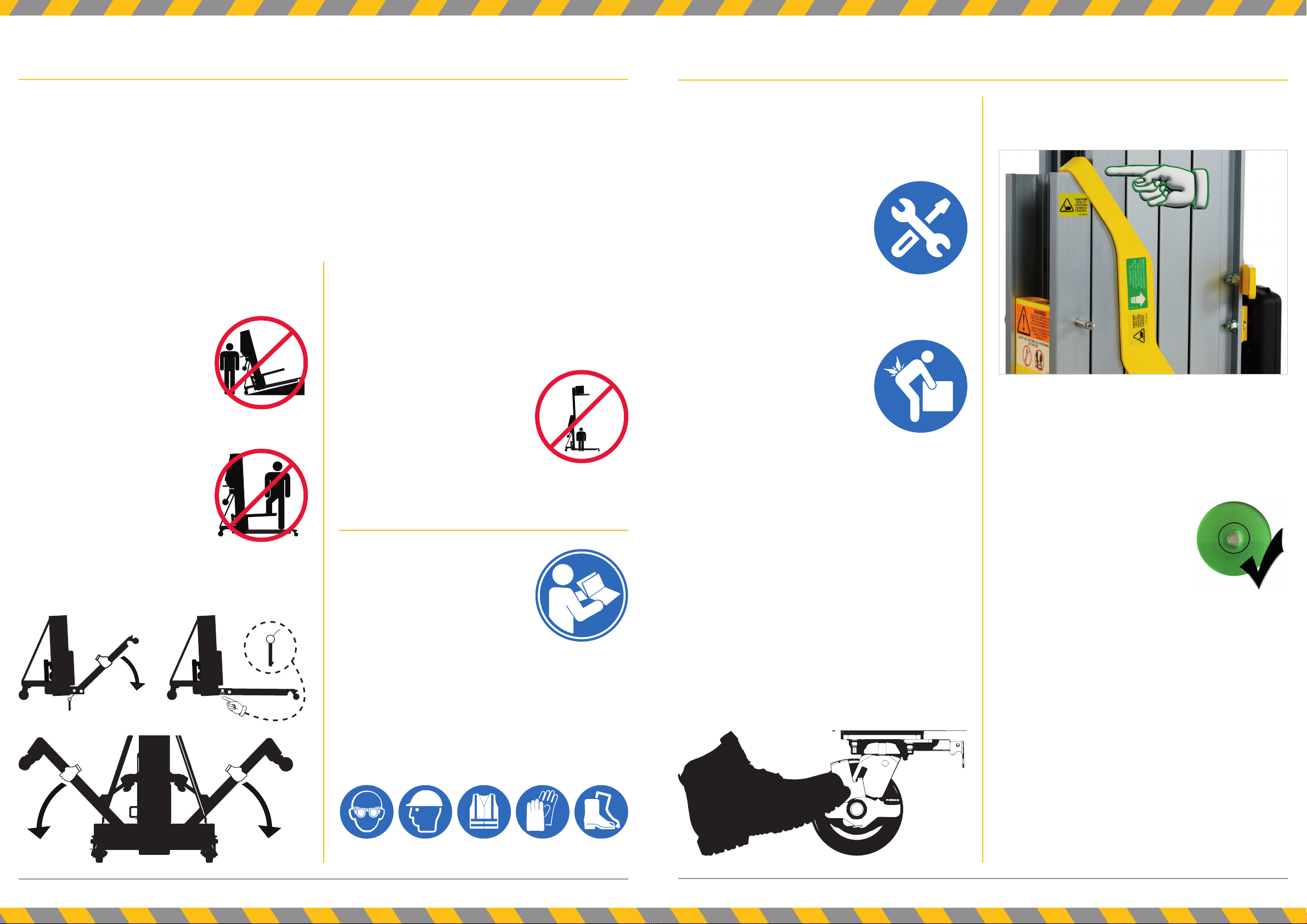
ALWAYS engage the carriage lock when moving
the machine around a worksite or workshop, or
from site to site on a delivery vehicle.
ALWAYS be aware of the following potential
nger trap points when setting up the machine:
2 front leg joints
2 stabiliser leg joints (if tted)
Carriage lock
Carriage
ALWAYS check that the machine
is level before raising the mast by
ensuring the bubble in the spirit
level is within the black circle.
ALWAYS hold the front leg when
the retaining pin is removed as it
will drop.
ALWAYS hold the stabiliser when the lock is
released as it will drop.
ALWAYS grip the winch handles until the winch
brake is locked i.e., when the weight of the load
will not cause the winch handles to turn.
ALWAYS engage the ratchet system before
releasing the winch handles by turning the winch
handle ¼ turn clockwise (away from you/raising
the load) to ensure that the ratchet/brake system
is engaged before winding up the mast to the
desired working height.
ALWAYS ensure that xings intended for one
time use e.g., self-locking nuts, cotter pins, roll
pins etc. are not reused.

12 13ToughLift®Material Lifts Maintenance ManualToughLift®Material Lifts Maintenance Manual
Section 4 – Competent Person for Thorough Examination AttributesSection 3 – Service Engineer Attributes
The ToughLift®Material Lifts and accessories service engineer should:
1. be physically t and competent to carry out the work being undertaken.
2. have a responsible attitude.
3. demonstrate an ability to learn.
4. be able to communicate clearly with other personnel on site.
5. be able to identify equipment.
6. be able to demonstrate an understanding of, and apply the information contained in this
Maintenance Manual.
7. be able to demonstrate that they can diagnose, rectify, and record faults.
8. be able to demonstrate an understanding and knowledge of how to carry out inspections (other
than thorough examinations) and be able to make recommendations for the continued use of the
equipment.
9. be able to demonstrate an understanding of and apply company procedures.
10. be able to demonstrate that they can operate the equipment safely.
11. be able to demonstrate that they can carry out functional checks.
12. be able to demonstrate knowledge of how to record all maintenance work carried out.
13. be able to demonstrate the required knowledge and expertise of the ToughLift®Material Lifts and
accessories for service and maintenance purposes.
14. be undergoing a form of Continuous Professional Development.
The competent person carrying out a thorough inspection of a ToughLift®Material Lift or accessory
should:
1. be physically t.
2. have a responsible attitude.
3. demonstrate an ability to learn.
4. be able to communicate clearly with other personnel on site.
5. comply with BS EN ISO/IEC 17020.
6. be capable of detecting defects or weaknesses in the ToughLift®Material Lift and accessories for
the purpose of the thorough examination.
7. have sucient knowledge and experience to assess the importance of defects or weaknesses in
the ToughLift®Material Lift and accessories, and be able to identify what actions need to be taken
to rectify them. They should be able to:
a. verify that the ToughLift®Material Lift and accessories are operating as intended in
accordance with the Instruction Handbook.
b. identify defects or weaknesses which could compromise the use of the ToughLift®Material
Lift and accessories.
c. specify the appropriate timescales within which identied defects or weaknesses need to be
rectied.
d. establish that defects identied in the previous report of thorough examination have received
attention.
e. assess that safety devices are functioning correctly.
f. check that warning notices are correctly xed and legible, and where necessary specify any
limitations to the use of the ToughLift®Material Lift and accessories.
g. carry out any testing required as part of the thorough examination.
h. report on the ndings of the thorough examination.
Please refer to the Appendix in this Maintenance Manual which details the information to be contained in
a report of a LOLER thorough examination (UK only, regulations in other countries vary).

14 15ToughLift®Material Lifts Maintenance ManualToughLift®Material Lifts Maintenance Manual
Section 5 – Periodical Maintenance & Checks /continuedSection 5 – Periodical Maintenance & Checks
WARNINGS
Failure to adhere to the Safety Rules below and the additional Safety Rules outlined in the
ToughLift®Material Lifts Instruction Handbook will result in serious injury or death.
Maintenance inspections shall be completed by a person trained and qualied in the
maintenance of a ToughLift®Material Lift.
Scheduled maintenance inspections shall be completed Daily/Pre-Use, 3-Monthly, and Annually,
as specied in the Maintenance Inspection Report.
The Daily/Pre-Use Maintenance Inspection must be undertaken by the owner of the machine
prior to the rst use of a new ToughLift®Material Lift.
The Daily/Pre-Use Maintenance Inspection must be undertaken by the owner of the machine
prior to each delivery to their customer.
The Daily/Pre-Use Maintenance Inspection must be undertaken if any situation has occurred
which could affect the safe operation of the machine e.g., toppling, signicant impact,
malfunctions etc.
The Daily/Pre-Use Maintenance Inspection must be undertaken following any repairs to a
ToughLift®Material Lift.
If a machine has been out of service for longer than 3 months, the 3-Monthly Maintenance
Inspection must be completed.
Failure to perform each procedure as shown and scheduled could cause death, serious injury, or
substantial damage.
Unless otherwise specied, perform each procedure with the machine in the following
conguration:
♦Machine parked on a solid and level surface.
♦Carriage fully lowered.
♦Swivel castors on splayed legs locked.
♦Standard Forks or Boom tted to the carriage.
Immediately tag and remove from service any damaged or malfunctioning ToughLift®Material
Lift.
Repair any machine damage or malfunction before operating the machine.
Use only ToughLift®approved replacement parts.
Notes:
The Lifting Operations and Lifting Equipment Regulations 1998 (LOLER) requires that lifting
equipment must be THOROUGHLY EXAMINED every 12 months. However, removable accessories
i.e., Standard Forks, Pipe Cradle, Extension Forks, Load Platform, or Boom, must be inspected
every 6 months. Please refer to the Appendix in this Maintenance Manual which details the
information to be contained in a report of a thorough examination (UK only, regulations in other
countries vary).
It is essential that only ToughLift®approved replacement parts are used when maintaining and
servicing ToughLift®Material Lifts and accessories. Failure to do so could result in an unsafe
machine. Please provide the following information when requesting replacement parts:
♦Name of model i.e., ML-10, ML-15, ML-20, or ML-25 or name of accessory i.e., Standard Forks,
Pipe Cradle, Extension Forks, Load Platform, Boom, or Rough Terrain Wheel Kit.
♦To be found on the manufacturer’s plate xed to the chassis of the machine or xed to the
accessory:
• Serial Number
• Year of Construction
♦Date of purchase of machine or accessory.
♦Part number from this Maintenance Manual.
♦Description from this Maintenance Manual.
♦Quantity required.
♦Purchase order number.
♦Company invoice address.
♦Delivery address with contact name and phone number at this address.
The ToughLift®Material Lift has been designed to operate for 10 years, providing that it is
maintained in accordance with the periodical maintenance and checks outlined in this section.

16 17ToughLift®Material Lifts Maintenance ManualToughLift®Material Lifts Maintenance Manual
Section 5 – Periodical Maintenance & Checks /continuedSection 5 – Periodical Maintenance & Checks /continued
Maintenance Inspection Report
Instructions
Make copies of this report to use for each inspection undertaken.
Select the appropriate checklist(s) for the inspection(s) to be performed.
Tick the appropriate box after each item is inspected i.e., P = Pass / F = Fail / R = Repaired &
reinspected.
Use the step-by-step procedures in this section to learn how to perform each inspection.
If any inspection receives an “F”, remove the machine from service, repair, and reinspect it. After a
completed repair and reinspection tick the R box.
1: Daily/Pre-Use
2: 3-Monthly
3: Annually
Model Name i.e., ML-10, ML-15, ML-20, or ML-25
Model Serial Number (from plate on chassis)
Removable Part Fitted (
)Serial Number
Standard Forks
Stabiliser - Left N/A
Stabiliser - Right N/A
Pipe Cradle - Left
Pipe Cradle - Right
Extension Fork - Left
Extension Fork - Right
Load Platform
Boom
Rough Terrain Wheel Kit N/A
Inspection Frequency Inspection Procedures Undertaken (
)
Daily/Pre-Use 1
3-Monthly 1 + 2
Annually 1 + 2 + 3
Item Ref. Activity P F R
a Inspect the Instruction Handbook, decals, and plates.
b Pre-operation inspection.
c Function tests.
Comments:
Item Ref. Activity P F R
a Inspect all welds.
b Clean the mast columns.
c Check the winch operation.
d Carriage lock deployment and de-deployment.
e Inspect and lubricate the winch.
Comments:
Item Ref. Activity P F R
a Inspect the mast assembly for wear.
b Test the mast safety brake.
c Replace the winch friction discs.
d Visual inspection and testing of all wheels and castors.
eLubrication of the braked swivel castors on the splayed legs and the front
leg swivel castors.
f Inspect the yellow powder coated fabrications.
Comments:
WARNING
Ensure the left and right stabiliser are tted to an ML-20 and ML-25. The ML-20 and ML-25 MUST NOT
be used without stabilisers.
Date of Inspection:
Machine Owned By:
Inspector Name:
Inspector Title:
Inspector Company:
Inspector Signature:

18 19ToughLift®Material Lifts Maintenance ManualToughLift®Material Lifts Maintenance Manual
Section 5 – Periodical Maintenance & Checks /continued Section 5 – Periodical Maintenance & Checks /continued
How to Perform Each Inspection
1: Daily/Pre-Use
a. Inspect the Instruction Handbook, decals, and plates.
c. Function tests
b. Pre-operation inspection
The Pre-Operation Inspection is a visual check performed by the operator of the ToughLift®Material Lift
prior to each work shift. The inspection is designed to discover if anything is wrong with a machine
before the operator performs the function tests. The inspection also identies if any routine
maintenance is required.
Note:
The operator should only inspect what they can see with the mast of the ToughLift®Material Lift
lowered.
Undertaking the function tests on the following page is essential to the safe operation of a ToughLift®
Material Lift. These tests are designed to identify any malfunctions before the machine is used.
If any malfunctions are identied, the machine must not be used, and must be tagged and removed from
service until such time as it has been repaired by a trained, competent, and authorised maintenance
engineer or technician.
Note:
Contact the manufacturer or your dealer for replacement document holder, Instruction Handbook,
decals, or plates.
The Instruction Handbook is stored in the document holder mounted on the back of the xed mast
column:
♦Check that the document holder is in position as shown in the image below.
♦Open the document holder by releasing the 2 clips on the top.
♦Check that the A5 Instruction Handbook shown in the image below is present.
♦Take the Instruction Handbook out of the document holder and check that each page is clearly
legible.
♦Put the Instruction Handbook back in the document holder and close it.
Check the following fabrications and components for areas of damage, improperly installed or
missing parts, and unauthorised modications:
♦Mast columns.
♦Cable anchor.
♦Pulleys.
♦Cable (look for kinks, frays, and abrasions).
♦Winch and related components.
♦Chassis.
♦Front legs.
♦Stabilisers and latch plates (if tted).
♦Carriage lock.
♦Wheels and castors (including Rough Terrain Wheel Kit, if tted).
♦Nuts, bolts, and other xings (in place and properly tightened).
♦Load handling attachments (as applicable): Standard Forks, Extension Forks, Load Platform,
Pipe Cradle, and Boom.
Check the entire machine for:
♦Dents or damage.
♦Corrosion or oxidation.
♦Cracks in welds or structural components.
Ensure there is a minimum of 4 wraps of cable around the winch drum when the carriage is fully
lowered.
Referring to Section 9 of this Maintenance Manual ensure that all decals and manufacturer’s
plates are in place and legible.
...continued over the page

20 21ToughLift®Material Lifts Maintenance ManualToughLift®Material Lifts Maintenance Manual
Section 5 – Periodical Maintenance & Checks /continued Section 5 – Periodical Maintenance & Checks /continued
Deploy each of the two front legs and ensure that they can be locked in position with the retaining
pins attached to the machine.
If tted, deploy each of the two stabilisers and ensure that they are locked in position when the
latch plates are released.
Check that the machine is level by ensuring the bubble in the spirit level is within the black circle.
Turn the winch handles 2 full turns anticlockwise (towards you) to release the pressure of the
carriage against the carriage lock.
Pull the spring-loaded carriage lock towards you, rotate clockwise, and release to latch in the xed
mast column.
With the load handling attachment tted to the carriage, raise the carriage by rmly grasping the
winch handles and rotating them clockwise (away from you). The winch should operate smoothly,
free of hesitation, or binding.
Lower the carriage by rmly grasping the winch handles and rotating them anticlockwise (towards
you). After lowering to the desired position, turn the winch handles clockwise (away from you) ¼
turn to set the brake. The winch should operate smoothly, free of hesitation, or binding.
With the mast lowered, the swivel castor brakes applied, and on a level surface, using the handles
try to push the machine to ensure that the brakes are fully functioning.
2: 3-Monthly
a. Inspect all welds
c. Check the winch operation
b. Clean the mast columns
1. Visually inspect all the winch components for damage or wear.
2. Fit either the Standard Forks or Boom to the carriage and add a load, ensuring that it is properly
secured.
3. Raise the carriage and release the winch handles.
Result: The winch should operate smoothly, free of hesitation or binding. The load should not
lower when the winch handles are released.
4. Fully lower the carriage.
Result: The winch should operate smoothly, free of hesitation or binding.
Note:
If, upon inspection, only the inner channels require cleaning, this cleaning can be undertaken from
ground level.
WARNINGS
Do not place ladders or scaffolding on or against any part of the machine.
Do not use ladders to undertake this procedure.
Performing this procedure without the proper skills and tools could result in
serious injury or death.
This is a visual inspection of all welds across the machine paying particular attention to the following
areas:
Winch.
Loading wheels/push and steer handles adjustable mount bracket.
Loading wheels/push and steer handles leg to cross bar.
Chassis; splayed legs, front legs mount, and stabiliser mount.
Front legs castor mounts.
Stabilisers (if tted): castor mount and stabiliser brace mount.
Any load handling attachments tted:
♦Standard Forks; all welds.
♦Boom; all welds.
Rough Terrain Wheel Kit (if tted); ‘T’ section weld.
The inspection is designed to identify any cracked or heavily corroded welds.
It is essential that the mast columns are kept clean to ensure that the machine operates as intended.
If the ToughLift®Material Lift is being used in very dirty conditions, the columns may need to be cleaned
more often.
The recommended procedure is as follows:
Raise the machine to full height so that all the mast columns are visible at the front and back of
the mast.
From the platform of a suitable Mobile Elevating Work Platform (MEWP), visually inspect the inner
and outer channels of the columns for debris and/or other foreign material.
Should any debris or foreign material be identied:
♦For dry debris, use a soft brush, starting at the carriage and top mast lifting column, working
down to the xed mast column.
♦For a general surface clean:
• Use a soft cloth and either soap and water, or if the surface is greasy, a degreasing spray
e.g., brake and clutch cleaner. Note: DO NOT get any brake and clutch cleaner on the
yellow coated surfaces of the machine.
• Start cleaning at the carriage and top mast lifting column, working down to the xed mast
column.

22 23ToughLift®Material Lifts Maintenance ManualToughLift®Material Lifts Maintenance Manual
Section 5 – Periodical Maintenance & Checks /continuedSection 5 – Periodical Maintenance & Checks /continued
d. Carriage lock deployment and de-deployment.
It is essential that damage to the carriage lock is identied in order that the machine can be safely used
and transported.
1. Fully lower the carriage.
2. Visually inspect the carriage lock for damage.
3. Pull the carriage lock towards you and rotate anticlockwise so that it locates over the carriage and
release it. The carriage lock should pull and rotate smoothly.
4. Wind up the carriage until it engages with the carriage lock. Ensure the carriage lock stays in
position over the carriage and prevents any movement of the carriage.
e. Inspect and lubricate the winch.
It is essential that the winch is properly maintained in order that the machine can operate safely and at
optimal performance.
If the winch has excessive wear and/or does not operate smoothly, free of hesitation and binding, it is
unsafe to use.
1. Carefully lubricate the following areas with Lithium EP2 Grease:
a. The 2 pinion shaft bushes.
b. Threads on the pinion shaft, under the pinion gear.
2. Carefully lubricate both pivot points on each ratchet pawl with SAE 30 Motor Oil.
3. Measure each friction disk for wear and replace both friction disks if the thickness measured is
less than 1.5 mm.
4. Measure both pinion shaft bushes for wear and replace both if the wall thickness measurements
are less than 3.1 mm.
5. Lubricate the drum pivot bolt with a thin layer of Lithium EP2 Grease. Tighten the drum bolt using
a torque spanner set to 27Nm (19.9ft-lbs). DO NOT over tighten.
WARNING
DO NOT get any Lithium EP2 Grease or SAE 30 Motor Oil on the brake friction disks or ratchet gears.
3: Annually
a. Inspect the mast assembly for wear.
b. Test the mast safety brake.
It is essential that excessive or unusual wear in the mast assembly is identied in order that the machine
can operate safely.
If the mast assembly has excessive wear and/or does not operate smoothly, free of hesitation and
binding, the machine must not be used.
1. Remove the load handling attachment from the carriage.
2. If the carriage lock is engaged, pull it towards you and rotate clockwise to latch in the xed mast
column.
3. Inspect the inner channel, pulley wheel, pulley wheel guard, and cable of the rst lifting column.
4. Wind up the carriage and rst lifting column to inspect the outer channel of the rst lifting column
and the rollers, cable, and the inner channel of:
a. If the model is an ML-10, the xed mast column.
b. If the model is an ML-15, ML-20, or ML-25, the second lifting column.
It is essential that a damaged or faulty mast safety braking system be identied in order that the
machine can operate safely. An unsafe working condition exists if the system is damaged or faulty and
does not allow the mast to raise or lower, free of hesitation and binding.
WARNING
Beware of sharp edges. ALWAYS wear suitable protective gloves when performing this procedure.
1. Fit either the Standard Forks or Boom to the carriage, but do not add any load.
2. Using the winch normally, raise the carriage until it is at a suitable height e.g., waist height, up the
rst lifting column as shown in the graphic below.
Note:
Repeat Step 4 (model dependent) until all the mast columns, rollers, and cable have been inspected.
...continued over the page

24 25ToughLift®Material Lifts Maintenance ManualToughLift®Material Lifts Maintenance Manual
Section 5 – Periodical Maintenance & Checks /continuedSection 5 – Periodical Maintenance & Checks /continued
3. Grasp the bottom of the Standard Forks or Boom, lift around 13cm, and then drop.
Result: The safety brake should engage, and the carriage should stop within 8cm from the drop
height.
4. Manually lift the Standard Forks or Boom approximately 4cm to disengage the safety brake.
WARNING
NEVER stand directly under the carriage or load handling attachment.
5. Remove the Standard Forks or Boom from the carriage.
6. Operate the winch until the rst lifting column is halfway up the adjacent column as shown in the
graphic below.
8. Holding the F-clamp, lift the rst lifting column approximately 4cm to disengage the safety brake.
9. For ML-15, ML-20, and ML-25 models, repeat Steps 6-8 until all mast lifting columns have been
tested.
WARNING
NEVER stand directly under the mast column, carriage, or load handling attachment.
7. Attach an F-clamp to the bottom of the rst lifting column as shown in the graphic below. Grasp
the long handle of the clamp and lift it approximately 13cm and then let go of the handle.
Result: The safety brake should engage, and the rst lifting column should stop within 8cm of the
drop height.
c. Replace the winch friction discs.
It is essential that the winch is properly maintained in order that the machine can operate safely and at
optimal performance.
If the winch has excessive wear and/or does not operate smoothly, free of hesitation and binding, it is
unsafe to use.
To replace the winch friction discs, follow the procedure below.
Note:
Refer to the exploded drawing of the winch on Page 50 as a useful guide to the terminology used in the
procedure below.
1. Start with the mast vertical.
2. Apply the brakes to the swivel castors on the splayed legs.
3. Remove the cable guard from the back of the xed mast column.
4. Lower the carriage until the lifting cable becomes loose and unwind all the cable from the winch
drum.
5. Slightly loosen the locking nut on the lower cover bolt.
6. Remove the drum pivot locking nut.
7. Hold the drum and winch gear cover with your left hand while removing the drum pivot bolt with
your right.
8. Lift the drum out of the winch housing and place on the oor.
9. Remove the locking nut from the right-side handle and remove the handle.
10. Remove the 2 hexagonal jam nuts from the right side of the pinion shaft. Helpful tip: To speed up
the removal of the hexagonal jam nuts you can hold the nut with a spanner and wind the handle on
the left side.
11. Remove the e-clip from the inside of the winch housing on the left side of the pinion shaft.
12. Gently lever the ratchet pawls off the ratchet gear and gripping the handle at the left of the winch,
pull the pinion shaft to the left until you have created space between the right end of the pinion
shaft and the right inner side of the winch housing.
13. Slide the pinion plate, right-side friction disc, ratchet gear, and left-side friction disc off the right
side of the pinion shaft.
14. Unscrew the pinion gear and take off the right end of the pinion shaft.
15. Remove the pinion shaft from the winch housing.
16. Dispose of the old friction discs.
17. Clean all the parts removed from the winch.
18. Insert the pinion shaft removed in Step 15 and add the pinion gear, new left-side friction disc,
ratchet gear, new right-side friction disc, and pinion plate onto the pinion shaft.
...continued over the page

26 27ToughLift®Material Lifts Maintenance ManualToughLift®Material Lifts Maintenance Manual
Section 5 – Periodical Maintenance & Checks /continuedSection 5 – Periodical Maintenance & Checks /continued
19. Apply a small amount of Lithium EP2 Grease to the pinion shaft as shown in the graphic below.
20. Screw the pinion gear back onto the threaded section of the pinion shaft.
WARNING
Ensure that you do not get any grease on the friction disc side of the pinion gear or the left-side friction
disc.
21. Slide the pinion shaft all the way into the winch housing ensuring the ratchet pawls are engaging
with the ratchet gear.
22. Replace the e-clip on the inside of the winch housing on the left side of the pinion shaft which was
removed in Step 11.
23. Replace the 2 hexagonal jam nuts on the right side of the pinion shaft. Helpful tip: To speed up the
tting of these nuts you can hold the nut with a spanner and wind the handle on the left side.
24. Ret the right-side handle with the new locking nut supplied in the Friction Disc Kit (Part Number:
630067). Note: The right-side handle should be retted at a 180° angle to the left-side handle.
25. Add a little SAE 30 Motor Oil to both pivot points on each ratchet pawl.
26. Before replacing the winch drum, add a little Lithium EP2 Grease to the drum pivot points at each
side.
27. Lower the winch drum back into the winch housing ensuring that the drum gear meshes with the
pinion gear.
28. Insert the drum pivot bolt through the winch housing and winch drum.
29. Ret the winch gear cover.
30. Fit the new drum pivot locking nut supplied in the Friction Disc Kit (Part Number: 630067) and
torque to 27Nm (19.9ft-lbs). Over tightening the drum pivot locking nut may cause damage to the
frame spacer and prevent the drum from spinning freely. Note: Ensure that the head of the drum
pivot bolt is on the drum gear side of the winch.
31. Fit the new lower cover locking nut supplied in the Friction Disc Kit (Part Number: 630067) and
torque to 27Nm (19.9ft-lbs).
32. While holding the cable tight on the drum, rotate the drum and spool the cable onto the drum
evenly. Note: Ensure that there are at least four wraps of cable on the winch drum and note that
the cable out to the rst pulley at the top of the mast must be located at the front of the winch
drum i.e., the side closest to you as you stand behind the winch.
33. Check the proper operation of the winch by winding the carriage up and down the rst lifting
column.
34. Secure a test load to the Standard Forks or Boom and raise and lower to ensure that the machine
is operating in accordance with the Instruction Handbook.
35. Replace the cable guard.
WARNING
DO NOT get any Lithium EP2 Grease or SAE 30 Motor Oil on the brake friction disks or ratchet gears.
d. Visual inspection and testing of all wheels and castors.
1. Visually inspect the following for cuts, cracks, unusual wear, or any other damage:
a. Braked swivel castors on the splayed legs.
b. Front leg swivel castors.
c. Transport wheels mounted at the back of the front legs (with the front legs lifted into, and
locked in the transport position).
d. Loading wheels.
e. If stabilisers are tted to the machine, stabiliser swivel castors.
f. If the Rough Terrain Wheel Kit accessory is tted to the machine, rough terrain wheels.
2. With the machine on a level clean surface, push the machine and ensure that the:
a. The braked swivel castors on the splayed legs roll and swivel smoothly.
b. With the front legs lowered that the swivel castors on the front legs roll and swivel smoothly.
c. With the front legs and stabilisers (if tted) lifted into the transport position that the front leg
transport wheels roll smoothly.
d. With the stabilisers deployed (if tted), that the swivel castors on the stabilisers roll and
swivel smoothly.
e. If tted, that the rough terrain wheels on the Rough Terrain Wheel Kit roll smoothly.
3. Spin the loading wheels by hand and ensure that they roll smoothly.
4. Apply the brake to each of the braked swivel castors on the splayed legs and try to push the
machine. If the castor wheel can roll, investigate the reason why and undertake the necessary
repair which may require the replacement of the castor.
5. Apply the pedal operated straight-line lock to each of the braked swivel castors and ensure that
the castors are rmly locked and remain in a straight line when you push the machine.

28 29ToughLift®Material Lifts Maintenance ManualToughLift®Material Lifts Maintenance Manual
Section 6 – TroubleshootingSection 5 – Periodical Maintenance & Checks /continued
e. Lubrication of the braked swivel castors on the splayed legs and the front leg swivel castors.
f. Inspect the yellow powder coated steel fabrications.
Braked swivel castors Front leg swivel castors Grease gun coupler
Regular lubrication of the braked swivel castors on the splayed legs and the front leg swivel castors will
ensure the high performance of the machine and will extend the life of these castors.
If the ToughLift®Material Lift has been operated in extremely dirty conditions it is recommended that the
lubrication of the braked swivel castors on the splayed legs and the front leg swivel castors be carried
out more frequently.
The castors are greased as follows:
1. Fill a grease gun with Lithium EP2 Grease.
2. Attach a dual handle grease gun coupler (M6-M12), as shown in the image below, to the grease nipple.
3. Pump in the grease until you see it coming out of the bearing gap.
Note:
As shown in the graphics below there is one grease nipple on each braked swivel castor and on each
front leg swivel castor to grease the swivel bearings. Each castor is tted with sealed bearings in the
axle which do not require greasing.
Inspecting the powder coated nish of the steel fabrications of the machine is essential to its safe
operation and long service life.
An unsafe working condition exists if there is signicant damage to the powder coated surfaces that are
not corrected.
Re-coating or replacement of the steel fabrication will be required if blistering, rusting, or peeling are
identied by visual inspection.
Helpful tip:
It is easier to grease the front leg swivel castors with the front legs lifted up into the transport position.
Issue:
The machine has been laid down without the carriage lock engaged and the mast sections have slid
out of alignment.
Solution:
1. Slowly and carefully slide each mast section back into the transport position. Note: You may
need to release the mast safety brake in the carriage and in each lifting column. For further
guidance, refer to Section 7.4 in this Maintenance Manual.
2. Undertake a visual inspection to ensure that the cable is still properly routed over each pulley
wheel.
3. Lift the machine up so that the mast is vertical.
4. Using the winch, raise the mast to full height and then lower.
5. Engage the carriage lock by releasing and rotating anticlockwise.
6. Using the winch, wind up the carriage until it engages with the carriage lock.
7. You can now lay the machine back down for transport and the mast sections will be held in
place.
Issue:
The winch cable has become crossed on the winch drum.
Solution:
1. Remove the cable guard, taking care to retain the xings.
2. Unwind the whole cable until it is loose.
3. Wearing suitable safety gloves, hold the cable whilst slowly winding the winch clockwise, and
using your hand to guide the cable to lay neatly on the winch drum.
4. When the winch starts to move the carriage, take your hand off the cable.
5. Replace the cable guard removed in Step 1.
6. You can now use the machine normally in accordance with the Instruction Handbook.
Issue:
The cable has become loose and the mast braking system has engaged locking the movement of the
mast.
Solution:
Wind the winch to take up the slack in the cable and the mast brake will release. You can then use the
machine normally in accordance with the Instruction Handbook.

30 31ToughLift®Material Lifts Maintenance ManualToughLift®Material Lifts Maintenance Manual
7.1 Safety & instructions /continued7.1 Safety & instructions
Section 7 – Repair Procedures Section 7 – Repair Procedures /continued
WARNINGS
Machine repairs shall only be undertaken by a person trained and qualied in the maintenance of
a ToughLift®Material Lift and should take place in a suitably equipped workshop.
Immediately tag and remove from service any damaged or malfunctioning ToughLift®Material
Lift.
Repair any machine damage or malfunction before operating the machine.
Maintenance engineers and technicians must read, understand, and adhere to the safety rules
and operating instructions contained in the ToughLift®Material Lifts Instruction Handbook and in
this Maintenance Manual before undertaking any machine repairs.
Ensure the workshop has a rm level oor.
Ensure that you have prepared the necessary work area, tools, and components required for the
repairs being undertaken on a machine.
Use only ToughLift®approved replacement parts.
Read each procedure carefully and completely BEFORE undertaking each repair.
Use proper lifting techniques to tip the machine, or to t or remove load handling attachments to
or from the carriage.
Instructions
Select the appropriate repair procedure from this section after troubleshooting the issue with the
ToughLift®Material Lift.
Perform disassembly procedures to the point where repairs can be undertaken.
To reassemble, perform the disassembly steps in reverse order.
The torque settings for the xings on the machine and accessories are shown in the tables on the
page opposite.
TORQUE SETTINGS REFERENCE GUIDE (304 STAINLESS-STEEL IMPERIAL FIXING SIZES)
Note: This chart is designed to act as a guide only.
Torque Setting - A2-70 - Dry
Nominal Diameter
(Inches)
Thread Length
(Inches) Threads Per Inch Ft-lbs Nm
3/8 1-1/2 16 20.65 28
3/8 1-1/4 16 20.65 28
3/8 1 16 20.65 28
3/8 3/4 16 20.65 28
1/2 1-3/8 13 48.68 66
1/2 1-3/16 13 48.68 66
1/2 1 13 48.68 66
1/2 5/8 13 48.68 66
TORQUE SETTINGS REFERENCE GUIDE (304 STAINLESS-STEEL METRIC FIXING SIZES)
Note: This chart is designed to act as a guide only.
Torque Setting - Dry
Nominal Diameter
(mm)
Thread Length
(mm) Class Ft-lbs Nm
4 10 A2-70 1.48 2
5 12 A2-70 2.95 4
16 44 A2-70 103.26 140
18 31 A2-70 143.82 195
Note:
Unless alternative torque settings are specied elsewhere in this Maintenance Manual, use the torque
settings specied in the table above.

32 33ToughLift®Material Lifts Maintenance ManualToughLift®Material Lifts Maintenance Manual
7.2 How to remove the chassis /continued
Section 7 – Repair Procedures /continued
7.2 How to remove the chassis
Section 7 – Repair Procedures /continued
WARNINGS
This procedure requires 2 maintenance engineers or technicians; one to operate the hoist and the
other to manually guide the machine into place.
ALWAYS undertake a risk assessment.
1. Lock the swivel castors on the splayed legs outbound of the chassis in a straight line and apply
the brakes.
2. Remove the Standard Forks or Boom from the carriage.
3. Fully lower the carriage and deploy the carriage lock.
4. If tted, remove each stabiliser by removing the bolt from the mount on the splayed leg and the
bolt from the stabiliser brace mount at the rear of the xed mast column.
5. Deploy the loading wheels into the horizontal transport position and lock in place with the
retaining pin.
6. Attach an adequately rated lifting hook with safety latch, strap, or chain from an adequately rated
overhead crane to the hoisting and winching anchor located above the cable guard at the back of
the mast.
7. Place a structure capable of supporting the machine behind the xed mast column and carefully
lower the machine onto the structure as shown below. Note: DO NOT completely remove the lifting
hook with safety latch, strap, or chain from the hoisting and winching anchor in case the machine
should fall.
8. Remove each of the front legs by removing the bolt and retaining pin.
9. Prepare 2 trestles or other suitable structure(s).
10. Lift the machine off the ground with the hoist and attach an additional lifting strap through and
around the mast braces.
11. Lift the machine and lay it down with the front of the mast on the trestles as shown in the graphic
below. Note: The trestles should be carrying the weight of the machine and the hoist can now be
disconnected.
12. Remove the document holder by opening and unscrewing the 3 xings.
13. Remove the bolt from each mast brace mounting on the splayed legs.
14. Remove the carriage lock threaded rod from the mounting tube on the chassis.
15. Remove the 4 bolts shown in the graphic below. Note: One of the maintenance engineers should
support the chassis as these last xings are removed by the other maintenance engineer.
16. Remove the chassis from the machine.
17. Follow the steps above in reverse order to replace the chassis or t a replacement. Note: When
tting the new chassis, ensure that the mast and the chassis are square with each other.
7.3 How to disassemble the mast
Note:
Removal of the chassis is only necessary when the xed mast column is to be removed. Refer to Section
7.2 How to remove the chassis.
1. Lock the swivel castors on the splayed legs outbound of the chassis in a straight line and apply
the brakes.
2. Remove the Standard Forks or Boom from the carriage.
3. Fully lower the carriage and engage the carriage lock.
4. Ensure the front legs are raised into the transport position and locked in place with the retaining
pin.
5. If tted, ensure the stabilisers are raised into the transport position.
6. If tted, remove the Rough Terrain Wheel Kit.
7. Remove the cable guard.
8. Remove the 2 bolts from the cable anchor on the winch drum.
9. Remove all the cable from the winch drum.
10. Deploy the loading wheels into the horizontal transport position and lock in place with the
retaining pin.
11. Either manually, or using an overhead crane connected to the hoisting and winching anchor at
the top of the xed mast column, tip the machine backwards and lay on the oor as shown in the
graphic below.
...continued over the page

34 35ToughLift®Material Lifts Maintenance ManualToughLift®Material Lifts Maintenance Manual
7.3 How to disassemble the mast /continued 7.3 How to disassemble the mast /continued7.3 How to disassemble the mast /continued
Section 7 – Repair Procedures /continued Section 7 – Repair Procedures /continuedSection 7 – Repair Procedures /continued
WARNINGS
Use proper lifting techniques when removing the Standard Forks or Boom from the carriage and
when tipping the machine backwards to the horizontal position.
ALWAYS wear protective gloves when handling the mast cable.
ALWAYS undertake a risk assessment.
12. Remove the bolts from the cable anchor at the top of the rst lifting column.
13. Remove all the cable from the mast by pulling on the cable anchor removed in Step 12 above.
14. Slide the carriage approximately 30cm up the rst lifting column to expose the carriage down
stop mounting bolt attached to the bottom end of the rst lifting column. Remove the bolt and the
down stop.
15. To release the carriage safety brake:
a. Insert an Allen key through the slotted access hole in the carriage, as shown in Figure 1 below.
b. Locate the Allen key on top of the safety brake roller, as shown in Figure 2 below.
c. Pull the Allen key back against the safety brake roller and the safety brake is released.
Figure 1 Figure 2
Note:
You can also release the mast safety brake using a special tool. The Mast safety brake release tool
accessory (Part Number: 630085) is available to purchase from the manufacturer or your ToughLift®
Material Lifts dealer. See Section 7.4 of this Maintenance Manual for further information.
16. Remove the carriage by sliding it out of the bottom of the mast while holding the safety brake
roller in the released position with Allen key.
17. Slide the rst lifting column up approximately 15 cm to expose the 2 down stop shoulder bolts
attached to the bottom end of the second lifting column if you are working on an ML-15, ML-20, or
ML-25, or the xed mast column if working on an ML-10. Remove the shoulder bolts and the down
stops.
18. Insert an Allen key through the slotted access hole in the rst lifting column and pull on the safety
brake roller to release the mast safety brake.
19. Remove the rst lifting column by sliding it out of the bottom of the mast while holding the safety
brake roller in the released position with the Allen key.
20. For models ML-15, ML-20, and ML-25, repeat steps 17 to 19 for the remaining column(s).

36 37ToughLift®Material Lifts Maintenance ManualToughLift®Material Lifts Maintenance Manual
7.5 How to assemble the mast
Section 7 – Repair Procedures /continued
7.4 How to release the mast safety brake when servicing the mast
Section 7 – Repair Procedures /continued
The mast safety braking system may engage when the machine is tilted horizontally if the carriage lock
is not deployed. When the mast brake is engaged, the mast columns can extend but cannot retract. If
the safety braking system engages while you are servicing the mast, use one of the following methods
below to release the brake.
1. This method allows you to release each column in sequence, starting at the carriage and then
removing the lifting columns one at a time. Refer to Section 7.3 How to disassemble the mast.
2. This method allows you to release any column in the mast assembly regardless of its position but
requires a custom tool. The Mast safety brake release tool accessory (Part Number: 630085) is
available to purchase from the manufacturer or your ToughLift®Material Lifts dealer.
Insert the tool from the bottom of the column into the safety brake access slot in the inner
channel of the column as indicated in the graphic below. Reach through the far upper end of the
slot and position the short end of the tool above the safety brake roller. Slide the carriage or lifting
column away from the base of the mast while pulling back on the tool.
Refer to the graphic on Page 56 of this Maintenance Manual to see the routing of the cable in the mast
assembly.
1. Inspect all the mast component parts for wear and damage and replace as necessary.
2. Clean the carriage, mast columns, pulley wheels, pulley wheel guards, rollers, and mast safety
brake assemblies with a clean, soft cloth and either soap and water or if greasy, a degreasing
spray e.g., brake and clutch cleaner.
3. If the xed mast column is not attached to the chassis with the 4 xing bolts, position the xed
mast column on a bench or trestles capable of supporting the weight of the machine once
assembled. Ensure the xed mast column is open side up and level. Bolt the chassis to the xed
mast column as shown in the graphic below. If the carriage lock is not xed to the chassis, this
can also be reassembled to the tube on the chassis and then the carriage lock can be latched in
the xed mast column.
Note:
If the xed mast column is still attached to the chassis with the 4 xing bolts you can lay the
machine on the oor so that it is supported by the loading wheels and braked swivel castors
locked outbound of the chassis in a straight line with brakes applied as shown in the graphic
below.
4. Install all the column assembly components (removed during the disassembly in Section 7.3)
except for the column down stops. Apply a small amount of Lithium EP2 Grease between the
roller bolt head and the inside of the roller.
5. Slide the rst of the lifting column(s) into the xed mast column from the bottom (chassis end of
the mast). Stop inserting the lifting column when the top of the up stop is level with the bottom
edge of the xed mast column.
6. Repeat Steps 4 and 5 for the remaining lifting column(s), but DO NOT install the carriage.
Note:
The cable is installed after all the columns have been assembled.
25mm
60mm
410mm
...continued over the page
This manual suits for next models
3
Table of contents
Popular Lifting System manuals by other brands

Lippert Components
Lippert Components Happijac OEM INSTALLATION MANUAL

Kleton
Kleton MJ523 instruction manual

EZ-ACCESS
EZ-ACCESS PATHWAY HD Code Compliant Modular Access... installation manual

Woodpeckers
Woodpeckers QUICKLIFT owner's manual

Braun
Braun NL Millennium Series manual

SPIDER
SPIDER SC1000-RE quick reference