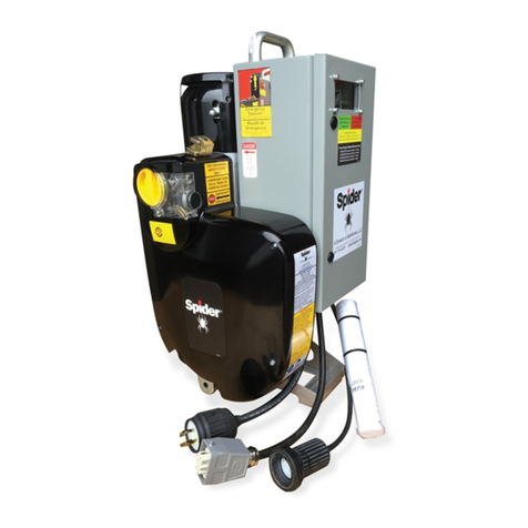
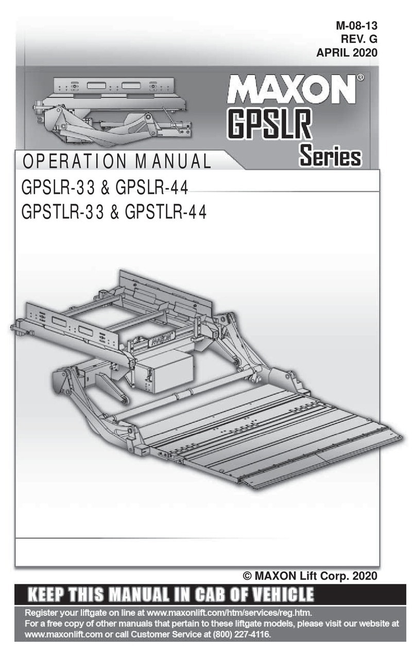
SPIDER SC1000-RE User manual

Hoist Operation Quick Reference
SC1000-RE Hoist
READ THE OPERATORS MANUAL BEFORE USING THIS QUICK REFERENCE
Normal Operation
• Conrm battery connection by verifying the UP operation Button is illuminated green. Verify battery charge level is
sucient for anticipated use 12 . Push in the UP operation button to display battery charge level.
• For routine travel in the UP direction, push in the UP operation button.
• For routine travel in the DOWN direction, push in the DOWN operation button.
• Both buttons are spring-loaded and will return to the OFF position AND apply the brake when released.
• After releasing the buttons, if the hoist does not immediately stop, press the emergency stopAND the overspeed
brake test button.
Unplug the power supply cable.
• Perform daily testing and inspection (see over) to ensure safe and correct operation. DO NOT use the hoist for
lifting until it has successfully completed the daily tests.
Reeving
• Push the primary suspension wire rope through the primary
suspension wire rope insertion point approximately
15 inches.
• Operate the hoist in the UP direction while pushing the rope
into the hoist.
• Ensure the wire rope runs freely through the Primary Wire
Rope Exit Guide.
• If the hoist is equipped with an optional secondary
suspension wire rope, push the secondary suspension wire
rope through the secondary suspension wire rope insertion
point until it exits the hoist 11 .
• Attach a 25 lb (11.5 kg) weight to the end of the secondary
wire rope to assist secondary wire rope travel.
723547-1 Revision: A
Overspeed
Reset Knob
UP Operation Button
and Power On (Green
Light)
Emergency Stop
(Power Supply Cut-off)
Primary Wire Rope
Insertion Point
Overspeed
Brake Test
Button
Primary Wire Rope
Exit Guide
DOWN Operation Button
and Overspeed Brake Trip
Indicator Light (Red Light)
Carrying Handle
Hour Meter and Battery
Charge Level Indicator 12
Power Supply
Cable
Remote Receptacle
Attach hoist to
stirrup bar
Optional Wire Rope
Insertion Point for
Secondary Wire Rope
Operating Instructions
Manual and Schematic
Emergency Descent
Lever Insertion Point
Motorshaft Access Plug
Model Designation
and Serial Number
Secondary Wire Rope
Exit Spring 11
(Optional Feature)
Optional Secondary
Suspension Wire Rope
Insertion Point
Primary Suspension Wire
Rope Insertion Point
Emergency Descent
Lever Storage

Dereeving Secondary Suspension Wire Rope
• In order to remove the optional secondary suspension wire rope, there must be no slack on the primary suspension
wire rope and the platform must be supported on a stable surface.
• Remove the counterweight from the end of the secondary suspension wire rope.
• Pull the secondary suspension wire rope out of the hoist by hand.
• If necessary, the primary suspension wire rope can now be removed from the hoist.
Dereeving Primary Suspension Wire Rope
For hoists equipped with the optional secondary wire rope, the secondary wire rope must be removed before
the primary wire rope is removed.
• WARNING!WARNING! To prevent hoists and platform from tipping and avoid injuries, ensure that the platform is properly
supported on a stable, at surface before putting slack on the primary suspension wire rope.
• Push in the DOWN operation button to wind the primary suspension wire rope out of the hoist. To remove
the last 15 inches (40 cm) of wire rope, if necessary, grab the wire rope above the primary suspension wire rope
insertion point, hold the overspeed brake reset knob in the reset position (vertical) and slowly pull the primary
suspension wire rope out of the hoist.
Daily Testing and Inspection
• Before operating the hoist, inspect the following:
▫ Wire rope, Power supply, Rigging, Platform, and Hoist
▫ All parts are present, in proper working order, and are not damaged.
▫ Bolts, nuts, and clamps are well secured.
▫ Ensure the hoist is secured to the stirrup with SAE Grade 5 fasteners and lock nuts that are properly installed.
• In a dirty environment that contains epoxy, paint, cement, sand blast residue, or corrosive material, inspect the
operation of the overspeed brake several times a day. Protective hoist covers are recommended. Contact your
supplier.
Battery charge level
• The battery will recharge as the hoist is operated in the down direction.
• Use the Battery Charge Level Indicator 12 to determine if there is sucient charge for anticipated use.
• If power is lost while suspended, use the emergency decent lever to lower the platform.
Test the Overspeed Brake
• While powering the hoist UP and DOWN
approximately 3 feet (1 meter), look through the
window into the overspeed compartment to see
whether the ywheel is turning.
Flywheel
• Dereeve the wire rope:
• Re-insert the wire rope about 12" (30 cm) into
the hoist.
• Holding the wire rope rmly, pull it out quickly. If
the brake is working correctly, it will grab and hold
the wire rope in less than 4" (10 cm). The DOWN
button will light up REDRED to indicate the overspeed
brake has activated and the DOWN circuit has been
interrupted.
• Repeat this test at least 3 times. If the brake does
not work correctly every time, DO NOT USE THE
HOIST. Return the hoist to your supplier.
• Reset the overspeed brake by turning the overspeed
brake reset knob clockwise.
Test the Overspeed Brake Test Button
• Push in the UP operation button and raise the platform approximately 3 feet (1 meter).
• Remove the Emergency Descent Lever from the storage location and insert into brake through the motor fan
shroud .
• Lift the Emergency Descent Lever. As the hoist begins to descend, push the Overspeed Test Button.
• The hoist MUST stop IMMEDIATELY!
Test the Emergency Stop Button
• While running the hoist in either direction, press the red emergency stop button.
• Once the emergency stop button has been pressed, the hoist should not move at all.
• To reset the emergency stop button, pull the button out.
Test the Emergency Descent
• Raise the platform approximately 3 feet (1 meter).
• Remove the Emergency Descent Lever from the storage location and insert into brake through the motor fan
shroud .
• Pull up the emergency descent lever SLOWLY, to make sure the hoist does not overspeed. The platform should
descend at a* slow, controlled speed.
WARNING!WARNING! If the overspeed brake trips while testing the emergency descent, the emergency descent system is not
working properly and THE HOIST SHOULD NOT BE USED.
Other SPIDER Lifting System manuals
Popular Lifting System manuals by other brands
Hinowa
Hinowa LIGHTLIFT 15.70 PERFORMANCE Quick instructions
Ravaglioli
Ravaglioli RAV261-2-L manual
Ravaglioli
Ravaglioli KPN345WE Translation of the original instructions
Southwire
Southwire Sumner GH2T-3 Operator's manual
The Handy
The Handy 20707G INSTRUCTIONS, PARTS DRAWING, PART LIST
EZ-ACCESS
EZ-ACCESS PATHWAY Classic Series Instructions for use
ALFRA
ALFRA TML 250 Operation manual
morse
morse 400AM-72-114 Operator's manual
TIGIEFFE
TIGIEFFE Airo V Series Use and maintenance manual
VMB
VMB Pro Lifts TL-063 Operating instructions & user manual

CM
CM 637 Series Operating, Maintenance & Parts Manual
KITO
KITO RY Series Assemble, Disassemble & Troubleshooting Instructions
