Anitech Systems Media Pro 4000 User manual

************************************************************************
Media Pro 4000 Brief March 8, 1999
File: HMT_INFO_BR030899.PDF
Module: HMT4010
Title: Handheld Monitor Terminal Operations Guide
************************************************************************
Note: This document is not available as a text-only file. This new brief
supercedes a document called scrnavig.doc/pdf, which will be removed from
public access. This document adds information about cabling for the HMT.
The body of the document follows this cover page and is in four parts.
First, the ‘Operation Guide’ presents an overview of procedures and
capability. Second and third are setup instructions for the two models of
handheld terminals that have been distributed by Anitech Systems, Inc.
And last, there is a section with notes about wiring and interconnect.
------------------------------------------------------------------------
Specifications subject to change at any time.
The data in this document incorporates proprietary rights of
Anitech Systems Inc., 25021 Anza Drive, Valencia, CA 91355 USA.
Phone (661) 257-2184 Fax (661) 257-2025
Any party accepting this document does so in confidence and agrees that
it shall not be duplicated in whold or in part, without the consent of
ANITECH SYSTEMS.
page 1 of 9.

vscreens.doc 9/2/98 R1.7 10/14/98
release OK
Media Pro 4000
Handheld Maintenance Terminal
OPERATIONS GUIDE
Anitech Systems Incorporated, 25021 Anza Drive, Valencia, CA 91355
This paper describes the operation of the handheld maintenance
terminal HMT4010 in viewing the ‘show display’, in accessing status
information, and in controlling show aspects for maintenance purposes.
INTRODUCTION
A handheld maintenance terminal (HMT) connected at the front panel of an ICM provides access
to system information, status, and control services that would otherwise require hundreds of
switches and indicators. By means of the Media Pro Network, the HMT provides access to every
resource in the system. With the menu system supported by the firmware in the ICM, it becomes a
‘virtual’ display and control panel for the entire Media Pro system.
Because the display size of the HMT is limited (4 rows of 20 characters), menus are used to permit
selection of the section of the ‘control panel’ which is of current interest. When the ICM is turned on
or reset, or the HMT is first plugged in, a signon message is presented giving the firmware versions.
After a few seconds, the HMT presentation switches to the ‘Show Display’, which is the destination
of DISPLAY commands in the Media Pro cues. Other ‘virtual’ screens can be accessed by user
with the ‘navigation’ keys. These keys are listed shortly below.
THE “SHOW DISPLAY”
A powerful feature of the Media Pro 4000 is that the show programmer can write ‘DISPLAY’
statements into the MPCL cues, and thereby put show status and other information onto the HMT
for examination during show operation. Typical uses are to put up a show version during the entry
to day mode, or to signal that certain cues are active or inactive; and, the HMT show display is
extremely valuable while ‘debugging’ cues and show operation.
As mentioned above, the show display is posted just a few seconds after the system is powered on,
or after the HMT is plugged in. To get into the menu system, the user enters an ESC, which goes to
the ‘top menu’. To return to the show display, the user gets to the top menu by pressing ESC, then
uses ENTER to move right, accepting the invitation GO TO SHOW DISPLAY.
The show display is maintained in the master ICM (rack ØØ), and its update is independent of
whether an HMT is plugged in or not. When the HMT is finally attached, the current show screen
will be posted, then updated regularly. The show display is also available with the MP4000
software, by clicking on the ‘HMT Enable’ window.
The show display is broadcast to all the slaves, and is presented there just as at the master rack.
MENU NAVIGATION
The menu system available on the HMT is to be considered as a two-dimensional array. A ‘top menu’
is at the upper left, at the top of the ‘select stack’, used to choose among the resources available for
inspection and control. Downward travel at this level cycles through the various choices, and ‘hotkeys’
can jump directly to a desired level. Some of the select menus require filling in ‘edit fields’ to specify a
particular resource, for example, choosing variable 4 (VØØ4).

Rightward motion from any menu is with the ENTER key. From the ‘select stack’, ENTER always
goes to the inspection level – information can be viewed, but no resource can be modified. At this
inspection level, pressing ENTER will move to the ‘control’ level. This is the final level, and can
only be entered if the password has been provided (more later).
At the inspection and control levels, downward motion is by means of F5, the ‘menu down’ key
(more below) and moves to other menus that provide information or control for the resource
selected at the ‘select stack’ level. If there are several menus pertaining to the resource, repeated
‘menu downs’ will cycle through them repeatedly, and (usually) F4, the ‘menu up’ key, will cycle
through the resource set backwards. (The F4/up exceptions are ususally in ‘help’ menus.)
NAVIGATION KEYS
The navigation keys are F1, F2, F3, F4, F5, ENTER, SPACE, BKSP, ? and ESC. The ESC key is
special: when pressed, the menu presentation is always moved to the ‘top menu’, even from the
‘show display’, providing the entry to the menu system. On some menus, especially at the control
level, other keys are active and have particular control effects usually described on the menu.
The F1 - F5 keys are ←→TAB ↑↓(cursor left, cursor right, next field, menu up, menu down).
F1, F2, and F3 are for movement in and among editable fields on the screen (if there are no
editable fields, these keys do nothing, more later). The ‘column left’ key (F1) & ‘column right’ key
(F2) move the cursor by columns in the editable fields. The TAB key (F3) always moves forward to
the next editable field (there is no reverse-tab, nor any vertical field moves).
F4 and F5 are for vertical motion in menu sets at a given level, as already described above.
The ENTER key is used to move rightwise to the inspection and control levels. In some cases, the
effect of the ENTER key will depend on the content of editable fields on the screen at the time, as in
the selection of a rack, slot, & port. In control menus, the ENTER key will cause the acceptance
and actuation of the data on the screen, but return to the same screen.
DATA FIELDS
At the inspection level and in many cases at the control level, the presentation is updated
continuously – if the value changes in the system, the HMT will report the new value. This is
valuable for watching the status of cues and variables, etc., and the output values of IOMs and
ASMs. The update is automatic, even if the source of the data is in another rack. Updates are as
frequent as it is noticed that the data value is changed – up to 30 times per second if the resource is
in the same rack as the HMT, possibly slower from other racks, since messaging in support of HMT
displays is given less priority than messaging that supports the operation of the show.
EDIT FIELDS
Several of the ‘select stack’ menus contain edit fields that specify the resource of choice. PORTS,
MODULES, CUES, VARIABLES, INPUTBYTES, and OUTPUTBYTES must be picked by entering
numbers onto the menu. Also, at the control level, new values are placed into edit fields before the
ENTER button does the actuation. Edit fields are distinguished from data fields in that a cursor will
appear in the first edit field when the menu is posted, and the TAB key (F3) will move the cursor to
any additional edit fields on the menu.
Edit fields are filled merely by pressing the desired keys on the HMT. These will be placed into the
edit field (generally) at the position where the cursor is blinking. When a field is filled, the cursor will
be positioned automatically at the beginning of the next edit field (or, if there is only one, at its

start). The value keyed into a field is checked at the last digit, and will be set to zero if the value
was out of range.
In an edit field, the F1 and F2 keys will cause the cursor to be repositioned in the previous or next
column. With the cursor in a column, the + and - keys (it is not necessary to ‘shift’ these keys)
cause that column to increase and decrease, unless the resultant value would be out of range. This
feature is useful in the control menus, where a port value can be ‘jogged’ using these keys.
In specifying ports, five edit fields are involved: rack, slot, port, ‘dot’, and bit. Only the first three are
presently routinely in the select menu: Rrr,ss,pp with the ‘dot’ and bit fields left off. Using the TAB
key to advance through the fields, or finishing the manual entry of ‘port’, the cursor will be located in
the ‘dot’ field just right of the ‘port’ field. Pressing the period (.) or ‘X’ key will cause the ‘dot’ field to
appear, and the cursor will be positioned in the bit field, now also visible. To undo the bit
reference, use TAB to again position the cursor over the ‘dot’, and press the period (.) or ‘X’ key
again. The ‘dot’ and bit fields will disappear.
HELP
The question mark key ‘?’ can be used on any menu except the show display. This will cause a
menu showing related help to appear, and the ‘menu down’ and ‘menu up’ keys can be used to
access additional screens of help text.
Generally, using ‘menu down’ will go to additional information that is still specific to the menu from
which the request was made, and ‘menu up’ will shift out to help about navigating the menus. From
a help menu, using the question mark (?) again will go to ‘help on help’.
The ENTER key from a help menu (if the user has not wandered too far), will go back either to the
previous menu, or eventually to the ‘top menu’.
RESOURCE ‘WALKING’
At the inspection or control levels, as has been said, using the ‘menu down’ and ‘menu up’ keys will
cause cycling within the list of information (or control) menus available for the selected resource.
However, it is often useful to ‘walk’ to other similar objects without going back to the select stack to
rekey the selection.
The SPACE key will serve to move the next similar resource, and BKSP will move to the previous
similar resource. For example, at the inspection level for cue 5 (QØØ5), the SPACE key will step
the display to cue 6, 7, etc., and BKSP will step the display to cue 4, 3, etc.
The exception to this procedure is that, if at the control level, SPACE or BKSP will first step back to
the inspection level for the chosen current resource.
PASSWORD
The MP4000 software permits designating an up-to-15-character alphanumeric password that is
downloaded to the ICMs with their configuration. If no password is specified, then entry to the
control level in the menu system is unimpeded. However, if a password is specified, then entry to
the control level is not possible until the user has given the correct password.
The password menu is at the control level of the SYSTEM select. The user enters the password
directly, but it is not echoed to the HMT (the text of ‘Anitech Systems’ is echoed, instead, to obscure
the vision of any observer). After putting in 1 to 15 characters, ENTER is pressed, and the top
menu is presented again. The success of the entry is not known until entry to the control level is
again attempted.

After a password has been entered, timers are started that cause the password to expire in one
minute, except that this time is extended indefinitely as long as any keys on the keypad are used.
The password will even survive forays to the show display. If the user wants the password
cancelled immediately, this can be done by simply pressing ENTER at the password menu without
entering any characters (or, enter a few characters that are NOT the password).
There is no ‘back door’ around the password; if it’s forgotten, it’s gone, unless the user has access to
the original show files under MP4000. So please don’t call us about this.
CONTROL KEYS
On some control-level menus, with or without edit fields, additional keys on the HMT keypad
become active. These are signalled on the menu or in the help. For example, in the cue control
menu, the prompt “P/play S/stop R/reset” appears at the bottom of the menu, indicating that
the keys P, S, and R will provide the indicated control.
MENU ARRAY
The following page or pages show the menu array. It is not fully complete, updates will be made as time permits.

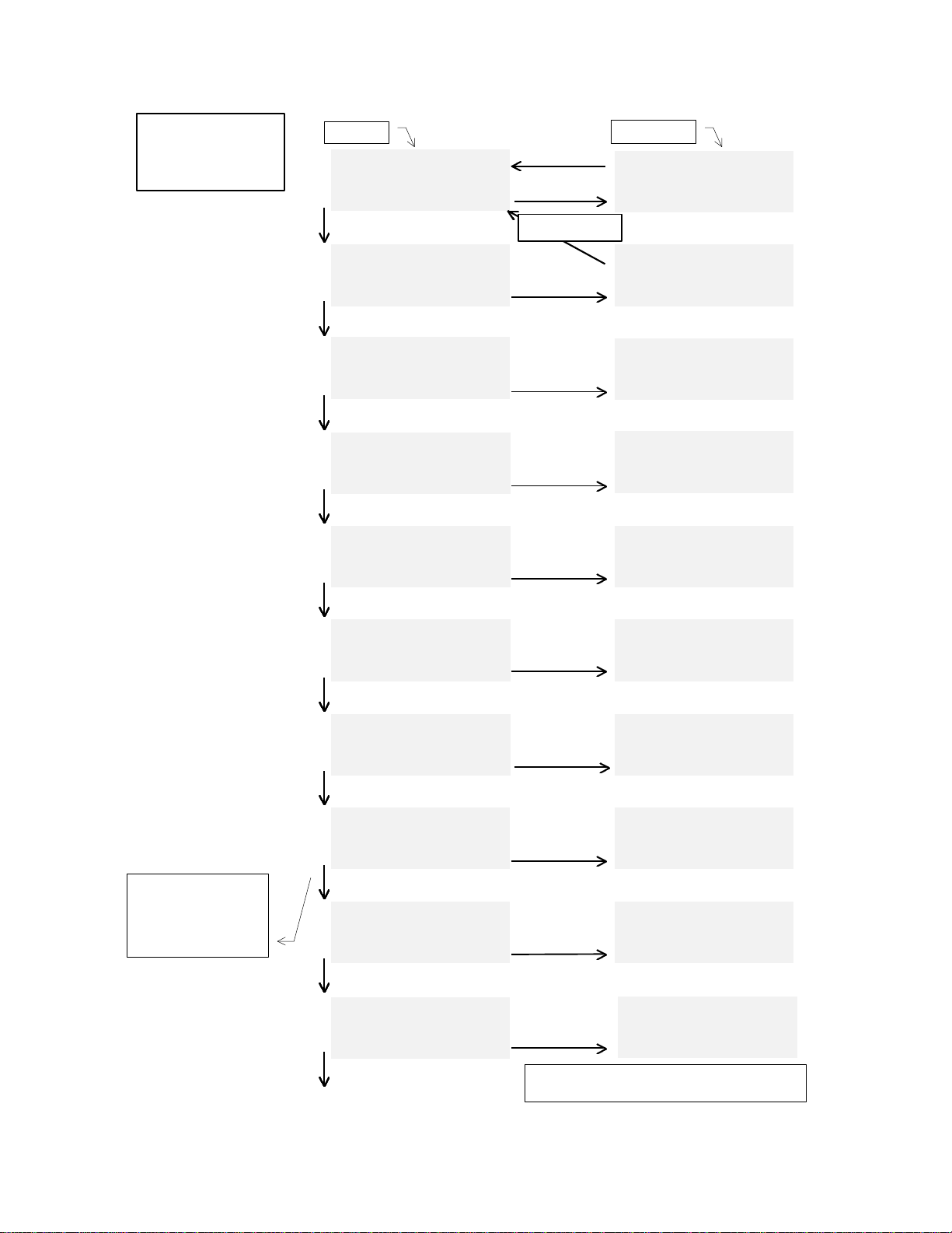
MENU MATRIX: SELECT LEVEL INSPECT LEVEL†
D→ESC
ENTER
DOWN
P→ESC
ENTER
DOWN
M→
ENTER
DOWN
Q→
ENTER
DOWN
V→
ENTER
DOWN
I→
ENTER
DOWN
O→
ENTER
DOWN
A→
ENTER
DOWN
S→
ENTER
DOWN
R→
ENTER
DOWN
(returns to top menu)
Select: ?=helpSelect: ?=help
GO TO SHOW DISPLAYGO TO SHOW DISPLAY
(this is rack# oo)(this is rack# oo)
ENTER,PMQVIOASR,?,F5ENTER,PMQVIOASR,?,F5
Select: ?=helpSelect: ?=help
SELECT PORTSELECT PORT
Roo,oo,oo.bb xxM40n0Roo,oo,oo.bb xxM40n0
ENTER,DMQVIOASR,?,F5ENTER,DMQVIOASR,?,F5
Select: ?=helpSelect: ?=help
SELECT MODULESELECT MODULE
Roo,oo xxM40n0Roo,oo xxM40n0
ENTER,DPQVIOASR,?,F5ENTER,DPQVIOASR,?,F5
Select: ?=helpSelect: ?=help
SELECT CUESELECT CUE
QoooQooo
ENTER,DPMVIOASR,?,F5ENTER,DPMVIOASR,?,F5
Select: ?=helpSelect: ?=help
SELECT VARIABLESELECT VARIABLE
VooVoo
ENTER,DPMQIOASR,?,F5ENTER,DPMQIOASR,?,F5
Select: ?=helpSelect: ?=help
SELECT INPUT BYTESELECT INPUT BYTE
IooooIoooo
ENTER,DPMQVOASR,?,F5ENTER,DPMQVOASR,?,F5
Select: ?=helpSelect: ?=help
SELECT OUTPUT BYTESELECT OUTPUT BYTE
OooooOoooo
ENTER,DPMQVIASR,?,F5ENTER,DPMQVIASR,?,F5
Select: ?=helpSelect: ?=help
SELECT SYSTEMSELECT SYSTEM
ENTER,DPMAVIOAR,?,F5ENTER,DPMAVIOAR,?,F5
Select: ?=helpSelect: ?=help
SELECT ANIMATIONSELECT ANIMATION
AoooAooo
ENTER,DPMQVIOSR,?,F5ENTER,DPMQVIOSR,?,F5
Select: ?=helpSelect: ?=help
SELECT REPORTSSELECT REPORTS
ENTER,DPMQVIOAS,?,F5ENTER,DPMQVIOAS,?,F5
Test Show Ver 1.0Test Show Ver 1.0
00:01:34.2500:01:34.25
H M1 C2 H M2 C3 H MH M1 C2 H M2 C3 H M
Entering Day Mode...Entering Day Mode...
H
O
T
K
E
Y
S
D
P
M
Q
V
I
O
A
S
R
d
i
r
e
c
t
t
o
m
e
n
u
Roo,oo,oo.bb xxM40n0Roo,oo,oo.bb xxM40n0
PORT VALUEPORT VALUE
ooh oooooooobooh oooooooob
ESC from ANYWHERE
goes to top menu!
STUBBED MENU,STUBBED MENU,
not yetnot yet
implementedimplemented
Cue ooo hh:mm:ss.ffCue ooo hh:mm:ss.ff
-state- hh:mm:ss.ff-state- hh:mm:ss.ff
rrrrrrrr event#!eeerrrrrrrr event#!eee
CUE Variable ooCUE Variable oo
dddddddddd oooooooohdddddddddd ooooooooh
w/Cue oooooooohw/Cue ooooooooh
INPUT Byte ooooINPUT Byte oooo
Value ooh ooooooooValue ooh oooooooo
w/Cue oooooooow/Cue oooooooo
OUTPUT Byte ooooOUTPUT Byte oooo
Value ooh ooooooooValue ooh oooooooo
w/Cue oooooooow/Cue oooooooo
ShowNameScrollsHere\ShowNameScrollsHere\
ShowCommentScrollsHeShowCommentScrollsHe
09/29/98 13:01:2309/29/98 13:01:23
STUBBED MENU,STUBBED MENU,
not yetnot yet
implementedimplemented
Anitech Systems Inc.Anitech Systems Inc.
Media Pro 4000Media Pro 4000
3220112A 09/23/98 003220112A 09/23/98 00
ICMBT228 03/04/98ICMBT228 03/04/98
This page shows the
select stack and the
first inspect menu
for each selection
(F5)
Generally, the UP (F4)
key will simply be the
opposite of DOWN (F5).
In some ‘help’ (?) series
there are exceptions.
top menu show display
†The actual ‘inspect-level’ menu format may be
different than exampled, depending on selection.

vscreens.doc 7/24/98 1/12/99 TERMIFLEX HANDHELD SETUP
If the ‘handheld’ terminal does not behave as outlined in the introduction, it may need to be set for
the proper communications and operations parameters before it can be used in the Media Pro 4000
system. The terminal itself has a menu system that is used as follows for setup:
1) Press CTRL and release, then press SHIFT and release, then press SPACE and release. The
terminal will display its MAIN MENU.
2) Press F1 to choose the COM (communications) setup menus.
3) Using F1 (previous), F2 (next), adjust the baud rate to 19.2K.
4) Use F4 (continue) to move to the next item, parity.
5) Using those keys, then, set the following parameters:
•BAUD RATE 19.2K
•PARITY none
•DATA, STOP BITS 8,1
•DISP SERIAL ERRORS no
•AUD SERIAL ERRORS yes
•SUPPORT XON/XOFF no
6) From the MAIN MENU, choose the DSP (display) and KBD (keyboard) and setup the following:
•DISP CTL CHARS no
•DISP ESC CHARS no
•CURSOR VISIBLE yes
•AUTO LINE WRAP no
•NEW LINE ON CR no
•DISPLAY SELF TEST yes
•BACKLIGHT LEVEL 7
•BACKLIGHT ON yes
•LOCAL ECHO no
•KEY REPEAT slow
•AUDIBLE KEYS no
•SIMPLIFIED KB no
7) In the keyboard setup menu, when you reach the PROGRAM FUNCTION KEY menu, press F5
(MAIN} and return to the top menu. Then press F5 (EXIT), press F1 (YES), to store changes, then
F5 (EXIT) one last time.

vscreens.doc 1/20/99 TWO TECHNOLOGIES HANDHELD SETUP
If the Two Technologies ‘handheld’ terminal does not behave as outlined in the introduction, it may
need to be set for the proper communications and operations parameters before it can be used in
the Media Pro 4000 system. The terminal itself has a menu system that is used as follows for
setup:
Press SHIFT and CTRL simultaneously. While continuing to press them, press F1.
The terminal will display its SETUP PARAMETERS MENU.
Use F2 to move forward through the parameter selections, F3 to move back.
For each parameter, a range of values is possible – the various values are displayed
consecutively as the F1 key is pressed repeatedly. To select the displayed value for
the parameter, simply use F2 or F3 to move to another parameter.
These are the values to select for each paramter:
•BAUD RATE 19200
•DATA BITS 8
•PARITY NONE
•STOP BITS 1
•CHARACTER REPEAT SLOW
•KEY CLICK ENABLED
•KNP FUNCTION DISABLED
•CURSOR ENABLED
•CURSOR BLINK ENABLED
•XON/XOFF DISABLED
•HANDSHAKING ENABLED
•ECHO DISABLED
•ESCAPE MODE PRIVATE
•CR/LF MODE NORMAL
•SELF TEST ENABLED
•SHIFT LOCK DISABLED
•SCROLL 81
•VIEW ANGLE MAX
•BREAK CMND DISABLED
•BACKLIGHT ON (see note)
When finished assigning values to all the parameters, press F5 to save the values to
memory and leave the SET PARAMETERS MENU.
BACKLIGHT note: the illuminator draws considerable current. If the terminal will be
used through more than a hundred feet of cable, the backlight should be set to OFF.

WIRING & INTERCONNECT CONSIDERATIONS
FOR THE HANDHELD MONITOR TERMINALS
Some of our clients are using the rear-DIN HMT connections from the ICM for cabling to outlets in
the show areas. Since the terminal operates at 19200 baud, it is important that the cable, routing,
and interconnect do not adversely affect communications with the HMT.
We have shown operation with 1000 feet of CAT-5 cable, end-to-end. At the baud rate used, cable
capacitance is a major concern, and any lesser quality cable should not be trusted more than a few
dozen feet from the driving ICM.
Also, using ‘star’ and/or ‘multidrop’ distribution arrangements can severely impair the quality of the
cable plant. For installations with very many outlets and long runs, users should consider using a
patch facility to avoid the complex configurations, and provide an essentially end-to-end operation
for every outlet in the show area.
Note that the handheld access is often associated with placements also intended for use with the
animation console over the Media Pro network, which is even less tolerant of star, multidrop, and
termination issues than the handheld – thus, facilities (such as patch panels) for dealing with the
animation consoles can easily also include provisions for the handheld terminal interconnect.
Finally, remember that environments with high amounts of electrical noise will affect the operation
of the handheld terminal and its interconnect. Communications cables should not be run in close
proximity to noise-sourcing cables or to power equipment, and should be protected against being
damaged.
Table of contents
Popular Touch Terminal manuals by other brands

March Products
March Products LIBRA 120 III (PC620) 120 III (PC620) user manual

Appostar
Appostar Grand POS GP-3464 user manual

IBM
IBM 4851 514 Planning, installation and service guide

protech
protech prox PA-J580 Quick reference guide

Mission
Mission MyDro M852L installation manual

Siemens
Siemens SRTNF3 installation instructions