ICP DAS USA GT-540P-3GWA-OEM2 User manual

GT-540P-3GWA-OEM2 user’s manual v1.0
2013/10 Ver. 1.0
GT-540P-3GWA-OEM2
Intelligent 3G Remote Terminal Unit With GPS
User’s Manual v1.0
High Quality, Industrial Data Acquisition, and Control Products

GT-540P-3GWA-OEM2 user’s manual v1.0
2013/10 Ver. 1.0
Warranty
All products manufactured by ICP DAS are warranted against
defective materials for a period of one year from the date of delivery to
the original purchaser.
Warning
ICP DAS assumes no liability for damages consequent to the use
of this product. ICP DAS reserves the right to change this manual at
any time without notice. The information furnished by ICP DAS is
believed to be accurate and reliable. However, no responsibility is
assumed by ICP DAS for its use, or for any infringements of patents or
other rights of third parties resulting from its use.
Copyright
Copyright 2013 by ICP DAS CO., LTD. All rights reserved
worldwide.
Trademark
The names used for identification only may be registered
trademarks of their respective companies.
Version
Version Date Author Description
1.0 2013/10/22 Alung Release version

GT-540P-3GWA-OEM2 user’s manual v1.0
GT-540P-3GWA-OEM2 user’s manual, Version 1.0, 2013/10 1/53
Table of Contents
1. Introduction ............................................................................................... 2
1.1 Features............................................................................................................. 4
1.2 Software Architecture....................................................................................... 4
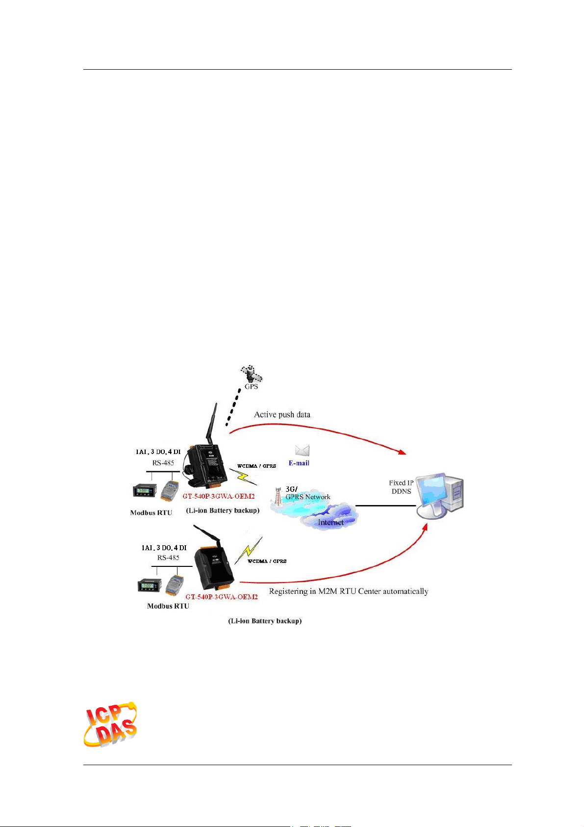
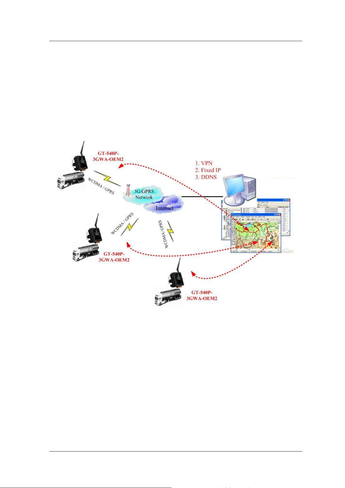
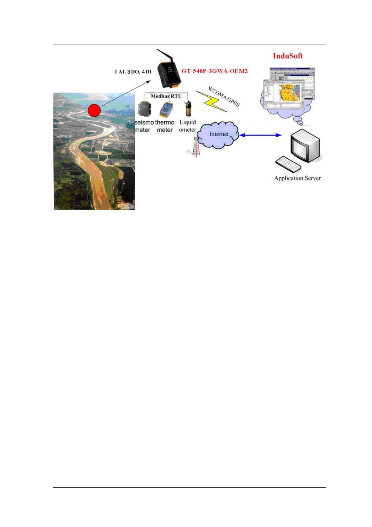
1.3 Applications...................................................................................................... 7
1.4 How to use GT-540P-3GWA-OEM2................................................................ 9
2. Hardware ................................................................................................. 10
2.1 Specifications ................................................................................................. 10
2.2 Appearance and pin assignments.................................................................... 12
2.3 Dimensions..................................................................................................... 13
2.4 DI/DO Internal Structure and Wire Connection............................................. 14
2.5 LED indicators................................................................................................ 15
2.6 Installing GT-540P-3GWA-OEM2................................................................. 16
2.7 How to reset GT-540P-3GWA-OEM2............................................................ 17
2.8 Charge and discharge of Li-Battery................................................................ 17
3. Installing GT-540P-3GWA-OEM2 Utility.............................................. 18
3.1 Installing .NET Framework............................................................................ 18
3.2 Installing GT-540P-3GWA-OEM2 Utility .....................................................20
4. GT-540P-3GWA-OEM2 Utility Operation............................................. 23
4.1 Main menu...................................................................................................... 24
4.2 Operation Language ....................................................................................... 26
4.3 Login............................................................................................................... 27
4.4 Main Parameters............................................................................................. 30
4.5 Device Status.................................................................................................. 43
4.6 Device Time.................................................................................................... 44
4.7 Counter Value ................................................................................................. 45
4.8 DO control/DI status/AI value........................................................................ 46
4.9 GPRS/GSM Signal Quality............................................................................47
4.10 Version............................................................................................................ 48
4.11 System ............................................................................................................ 49
5. Data logger .............................................................................................. 51
5.1 The naming rule of logger file name.............................................................. 51
5.2 The data format of the data logger file........................................................... 52
5.3 Delete Data Logger File Automatically.......................................................... 52
6. Trouble shooting...................................................................................... 53

GT-540P-3GWA-OEM2 user’s manual v1.0
GT-540P-3GWA-OEM2 user’s manual, Version 1.0, 2013/10 2/53
1. Introduction
The GT-540P-3GWA-OEM2 is the intelligent Active 3G Remote Terminal Unit product.
They are the highly integrated, stand-alone solution for M2M applications. Within the high
performance 32 bit CPU, the GT-540P-3GWA-OEM2 is suit for the hard industrial
environment. It features 3G module, 6 digital inputs, 2 digital outputs, 1 analog input, 2
RS-232, 1 RS-485 and micro SD interface. It can be used in M2M application fields to
transfer the local I/O and Modbus device’s data via 3G/GPRS by the defined period or
DI/AI triggers. The local I/O and GPS data can also be stored in the SD card to become a
remote data logger. For another communication mode, the GT-540P-3GWA-OEM2 offers
the e-mail mode to transfer the data by e-mail via 3G/GPRS for users to choose. The
simple I/O linkage function of the GT-540P-3GWA-OEM2 can reach the real time control
in the local field. It also supports Li-ion battery as another power source when the main
power is failed temporarily. Therefore, the GT-540P-3GWA-OEM2 is an ideal solution for
environmental monitoring and remote device management for M2M applications.
Meanwhile, it is supplied with easy-to-use API and OPC server Software that streamline
application development process, freeing system integrators from dealing with complex
communication protocols of 3G/GPRS and the Internet. In addition,
GT-540P-3GWA-OEM2 has the GPS function to apply in vehicle monitoring system.

GT-540P-3GWA-OEM2 user’s manual v1.0
GT-540P-3GWA-OEM2 user’s manual, Version 1.0, 2013/10 3/53
zEasy to Establish 3G/GPRS Network Applications
It is a big headache for engineers to establish the 3G/GPRS applications
because the dynamic IP management is required. Applying the
GT-540P-3GWA-OEM2 and M2M RTU center software, the dynamic IP addresses
can be managed between them. The remote 3G/GPRS RTU product would connect
to M2M RTU Center automatically. Therefore, all remote 3G/GPRS RTU devices
can be managed by s single centralized M2M RTU Center software with a fixed IP
address. Moreover, there are M2M API tool and OPC server for engineers to develop
the 3G/GPRS applications by VB, VC or SCADA development tools conveniently
without any IP address management effort.
zActive data transmission
The GT-540P-3GWA-OEM2 with active I/O transmission mechanism can
raise the communication. Unlike the traditional poll communication, it would
transfer the data by the defined time, DI trigger or AI hi/lo alarm. In addition to
improve the way of communication, that can also reduce the AP effort.
zTransfer data by e-mail
Expect for the transferring data by the general communication with the
M2M RTU center, users can choose the e-mail mode to send these data by
e-mail over 3G/GPRS network in the fixed time.
zModbus RTU device connectivity
The GT-540P-3GWA-OEM2 is built-in Modbus RTU protocol. That can
make any Modbus RTU device connect to the GT-540P-3GWA-OEM2. By the
way of GT-540P-3GWA-OEM2, Modbus RTU devices can be used in
3G/GPRS remote system. The max Modbus RTU device can be connected to
the GT-540P-3GWA-OEM2 is three.
zSimple Local I/O link Control
There are I/O built-in 3G/GPRS RTU devices of ICP DAS. Therefore,
these products can be the 3G/GPRS I/O devices. Expect for these local I/O
data can be sent to the host PC, the I/O link function of them help users to do
the simple control in local field. For example: the DI trigger or high/low AI
alarm can driver the DO channel.
zBuilt-in I/O Data Logging
The GT-540P-3GWA-OEM2 provides an external mircro SD interface.
These local I/O and Modbus data are recorded in SD memory card for one
day in a single file.

GT-540P-3GWA-OEM2 user’s manual v1.0
GT-540P-3GWA-OEM2 user’s manual, Version 1.0, 2013/10 4/53
1.1 Features
zAutomatic/continuous 3G/GPRS Link Management
zSupport Modbus RTU protocol to connect to Max 3 Modbus RTU devices via RS-485
port
zSupport M2M OPC server for SCADA system
zEasy-to-use API tool for users to develop their applications by various program
development tools
zCan be the 3G/GPRS I/O devices
zSupport GPS function
zSupport data transferring by E-mail
zLocal I/O linkage function to make the simple local control
zSupport data logger in micro SD card (Max : 4 GB bytes)
zSupport 3.7V Li-ion Battery backup
zPower supply 12VDC / 24VDC
1.2 Software Architecture
The M2M RTU center software with friendly Graphic interface is to manage the
3G/GPRS RTU products easily. Users can monitor the I/O data and status of 3G/GPRS
RTU device by the interface on PC. By using the M2M RTU API tool and M2M RTU
center software, any remote monitoring system can be achieved easily and efficiently. For
SCADA system, the M2M.OPC server is provided to connect to SCADA by OPC
interface.

GT-540P-3GWA-OEM2 user’s manual v1.0
GT-540P-3GWA-OEM2 user’s manual, Version 1.0, 2013/10 5/53
M2M RTU management software- M2M RTU Center
The M2M RTU Center provided by ICP DAS is a M2M (Machine to Machine)
management software that has a strong core technology for handling data and lets the user
save the trouble of dealing with large IO data. For detail information and downloading the
software, please refer to:
http://ftp.icpdas.com/pub/cd/usbcd/napdos/m2m/rtu/rtu_center

GT-540P-3GWA-OEM2 user’s manual v1.0
GT-540P-3GWA-OEM2 user’s manual, Version 1.0, 2013/10 6/53
M2M RTU SDK- M2M RTU API
ICP DAS M2M RTU Library is a software tool package for M2M RTU products. It
provides the seamless connection with M2M RTU products (G-4500 RTU,
GT-540P-3GWA-OEM2…) of ICP DAS for the user-designed system. With the APIs in
this library, programmer can access M2M RTU devices by public software development
environments, like VC, VB, BCB, visual studio.Net… It is easy to integrate these
3G/GPRS RTU devices to various applications including real the remote data, database
management system.
For detail information and downloading the software, please refer to:
http://ftp.icpdas.com/pub/cd/usbcd/napdos/m2m/rtu/m2m_rtu_win32_api
OPC server for RTU series of ICPDAS- NAPOPC.M2M DA Server
ICP DAS NAPOPC.M2M DA Server is an OPC software package operated as an OPC
driver of a HMI or SCADA system. It provides seamless connection with 3G/GPRS RTU
products (G-4500 RTU, GT-540P-3GWA-OEM2…) from ICP DAS to SCADA system
(InduSoft, Wonderware, iFix, Citec, LabView and etc) following OPC 1.0, OPC 2.0 Data
Access Standards.
For detail information and downloading the software, please refer to:
http://ftp.icpdas.com/pub/cd/usbcd/napdos/m2m/rtu/napopc.m2m
EzDatalogger
EZ Data Logger is a small data logger software. It can be applied to small remote I/O
system. With its user-friendly interface, users can quickly and easily build a data logger
software without any programming skill.
For the detail and downloaded from:
http://www.icpdas.com/products/Software/ez_data_logger/ez_data_logger.html

GT-540P-3GWA-OEM2 user’s manual v1.0
GT-540P-3GWA-OEM2 user’s manual, Version 1.0, 2013/10 7/53
1.3 Applications
zEarthquake and Landslide Alarm system
zHydrologic monitoring System
zVending machine automation system
zSewage flow monitoring system
zPiped water monitoring system
zVehicle monitoring system
Vehicle monitoring System

GT-540P-3GWA-OEM2 user’s manual v1.0
GT-540P-3GWA-OEM2 user’s manual, Version 1.0, 2013/10 8/53
Hydrologic monitoring System

GT-540P-3GWA-OEM2 user’s manual v1.0
GT-540P-3GWA-OEM2 user’s manual, Version 1.0, 2013/10 9/53
1.4 How to use GT-540P-3GWA-OEM2

GT-540P-3GWA-OEM2 user’s manual v1.0
GT-540P-3GWA-OEM2 user’s manual, Version 1.0, 2013/10 10/53
2. Hardware
2.1 Specifications
GT-540P-3GWA-OEM2
System
CPU 32 bit CPU
SRAM 64 KB
Flash Memory 512 KB
RTC Gives time(sec, min, hour) & date, leap year compensation
Watchdog Yes
Micro SD Inerface Max 4GB
Serial ports
COM1 RS-232 : TXD,RXD,GND for configuration
COM2 RS-485:D+,D- for Modbus RTU device connectivity
Digital Input
Channels 4
Input Type Sink or Source, Isolated channel with common power or
ground
Off Voltage Level +1V max.
On Voltage Level +3.5 ~ 30 VDC
Isolated Voltage 3750Vrms
Counters 6 (16 Bit, 5~40Hz), Min. Pulse Width : 25ms
Relay
Channels 3
Type Form A (SPST N.O.)
Operating Voltage
Range 250 VAC/30 VDC
Max. Load Current 5.0A/channel at 25°C
Electrical Life
( Resistive load )
5 A @ 250 VAC 50,000 ops
3 A @ 250 VAC 100,000 ops
Mechanical Life 20,000,000 ops. at no load
Analog Input
Channels 1
Resolution 12 bit
Input Range/Type 0 ~ 20 mA
2G System
GPRS Quad-band 850/900/1800/1900 MHz
GPRS multi-slot : class 10/8

GT-540P-3GWA-OEM2 user’s manual v1.0
GT-540P-3GWA-OEM2 user’s manual, Version 1.0, 2013/10 11/53
GPRS mobile station : class B
GPRS class 10 : Max download speed 85.6 kbps
Compliant to GSM phase 2/2+
-Class 4(2W @ 900 MHz)
-Class 1(1W @ 1800/1900 MHz)
Coding schemes : CS 1, CS 2,CS 3,CS 4
3G System
Frequency Band 850/900/1900/2100 MHz
Power class Class 3(250mW @ WCDMA/HSPA)
GPS Interface
Support Channels 32
Sensitivity Tracking = up to -159 dBm (with external LNA)
Cold start = up to -146 dBm (with external LNA)
Acquisition Time Hot start (Open Sky) = 2 s(typical)
Cold start (Open Sky) = 36 s(typical)
Protocol Support GPRSC format (NMEA 0183 version 3.01)
Power
Protection Reverse polarity protection
Frame Ground
Protection ESD, Surge, EFT, Hi-Pot
Required Supply
Voltage 12 VDC / 24 VDC
Mechanical
Casing Plastic
Flammability UL 94V-0 materials
Dimensions
(W x H x D) 91 mm x 132 mm x 52 mm
Installation DIN-Rail
Environment
Operating Temperature -25 °C ~ +75 °C
Storage Temperature -40 °C ~ +80 °C
Humidity 5 ~ 95% RH, non-condensing

GT-540P-3GWA-OEM2 user’s manual v1.0
GT-540P-3GWA-OEM2 user’s manual, Version 1.0, 2013/10 12/53
2.2 Appearance and pin assignments
The GT-540P-3GWA-OEM2 is with the GPS antenna connector and LEDs. The
following figure shows the appearance of GT-540P-3GWA-OEM2.
DI/DO
Terminal
No. Pin
Assignment
01 DI0
02 DI1
03 DI2
DI
04 DI3
DI COM 05 DI COM
N/A 06 N/A
07 RL0 COM
RL0 08 RL0 NO
09 RL1 COM
RL1 10 RL1 NO
11 RL2 COM
RL2 12 RL2 NO
13 AIn+
AI 14 AIn-
COM Port & Power Input
Terminal
No. Pin
Assignment
Ground for COM 01 GND
02 RxD1
COM1
RS-232 03 TxD1
04 D+COM2
RS-485 05 D-
06 RST+
Reset 07 RST-
08 DC.+VSPower Input:
12VDC / 24VDC 09 DC.GND
Frame Ground 10 F.G

GT-540P-3GWA-OEM2 user’s manual v1.0
GT-540P-3GWA-OEM2 user’s manual, Version 1.0, 2013/10 13/53
2.3 Dimensions

GT-540P-3GWA-OEM2 user’s manual v1.0
GT-540P-3GWA-OEM2 user’s manual, Version 1.0, 2013/10 14/53
2.4 DI/DO Internal Structure and Wire Connection
(1) DI Wire Connection
(2) Relay Wire Connection

GT-540P-3GWA-OEM2 user’s manual v1.0
GT-540P-3GWA-OEM2 user’s manual, Version 1.0, 2013/10 15/53
2.5 LED indicators
There are four LED indicators to help users to know the various conditions of
GT-540P-3GWA-OEM2. The description is as follows:
EXT(Red):Power LED to indicate whether the power is input or not. The description is
as follows:
The power is active The power is not active
on off
3G (Green):The modem LED can indicate the status of 3G module.
Modem normal Modem fail
GPRS
Mode Blanking per 3 sec
WCDMA
Mode Twinkling twice per 3 sec
Off
or
Blanking (not 3 sec)
STA(Orange):System LED is to indicate if the GT-540P-3GWA-OEM2 is normal or
fail.
Condition
External power Normal WCDMA/GPRS
Fail PIN code is wrong
On Blanking per 1
sec Always on or off Blinking per 50 ms
GPS (Green):GPS can indicate the status of GPS module
GPS normal GPS fail
Blinking per 1 sec Always on or off

GT-540P-3GWA-OEM2 user’s manual v1.0
GT-540P-3GWA-OEM2 user’s manual, Version 1.0, 2013/10 16/53
2.6 Installing GT-540P-3GWA-OEM2
It needs to follow these steps to install the GT-540P-3GWA-OEM2 below:
1. Install the 3G/GPRS antenna. GT-540P-3GWA-OEM2 must install GPS
antenna additionally.
2. Plug in the normal SIM card (Before apply the SIM card, confirm it is OK by
the mobile phone.)
3. Pin08 and Pin09 connect to the DC.+VS and DC.GND of the power supply.
4. Follow the section 2.4 to wire the I/O connection.
5. If you want to use the backup power, please connect the Li-battery to the
GT-540P-3GWA-OEM2.
6. It is needed to wait for 30 ~ 50 seconds to search the GSM base and register to
the ISP. After finishing the process, GT-540P-3GWA-OEM2 would be in
normal operation mode and the STA LED would blank per 3 sec. The start
time of GT-540P-3GWA-OEM2 depends on the strength of signal.

GT-540P-3GWA-OEM2 user’s manual v1.0
GT-540P-3GWA-OEM2 user’s manual, Version 1.0, 2013/10 17/53
2.7 How to reset GT-540P-3GWA-OEM2
The Li-Battery has been applied in GT-540P-3GWA-OEM2
1. Remove Li-Battery from GT-540P-3GWA-OEM2.
2. Turn off the external power and confirm the EXT LED is off.
3. Turn on the external power.
4. Re-install the Li-Battery.
The Li-Battery is not applied
1. Turn off the external power and confirm the EXT LED is off.
2. Turn on the power.
Reset Pins
1. Connect CON1.6 to DC.+VS
2. Connect CON1.7 to DC.GND
2.8 Charge and discharge of Li-Battery
If users apply the Li-Battery on GT-540P-3GWA-OEM2, the Li-battery would be
charged by the external power automatically. When the external power is removed from
GT-540P-3GWA-OEM2, the power supplying to GT-540P-3GWA-OEM2 is from
Li-Battery. When the power is only from Li-Battery, the running time of the
GT-540P-3GWA-OEM2 is depended on the frequency of transmission and the volume of
Li-battery. We suggest users to exchange the Li-Battery every 6 months.
ICP DAS provides 600 mAh and 1200 mAh Li-batteries for users to pick out and
buy.
Li-Battery ordering information
BT1200 3.7V 1200 mAh Battery

GT-540P-3GWA-OEM2 user’s manual v1.0
GT-540P-3GWA-OEM2 user’s manual, Version 1.0, 2013/10 18/53
3. Installing GT-540P-3GWA-OEM2 Utility
It needs the runtime environment with .NET Framework 2.0 or above to execute the
GT-540P-3GWA-OEM2 Utility in the PC. If there has .NET Framework 2.0 or above in
the PC, the section 3.1 can be omitted.
3.1 Installing .NET Framework
Please download the .NET Framework 2.0 on the Microsoft web site and install it.
The install figure is as follows:
(1) Press “Next" to the next step.
(2) Select the “I accept the terms of the License Agreement" and “Install "to
the next step.
Table of contents