Page 6 of 13
4.0 OPERATION
WARNING: Tube failure may result in fluid being sprayed from pump. Use appropriate measures to
protect operator and equipment. Tubing should be inspected periodically for tears, cracks, cuts, or
abrasions.
WARNING! Use only factory approved tubing from the designated tubing class. Incorrect tubing can
adversely affect performance or damage the pump.
4.1 Controls
3-Way Rocker Switch – All models are equipped with a 3-way rocker switch mounted on the front
of the pump. The Up and Down positions turn the pump ON in the clockwise and counterclockwise
direction, respectively, and the center position is OFF. Always confirm the switch is in the
designated OFF position before plugging the pump into any power receptacle.
Potentiometer – All models are equipped with a potentiometer on the front of the pump which is
used to regulate pump speed (output) and analogue signal scaling, depending on model.
Mode Switch – For models equipped with a remote operation function, a latching, push-button
switch is located on the back of the pump which activates and deactivates external control.
OUT=LOCAL; IN=EXTERNAL.
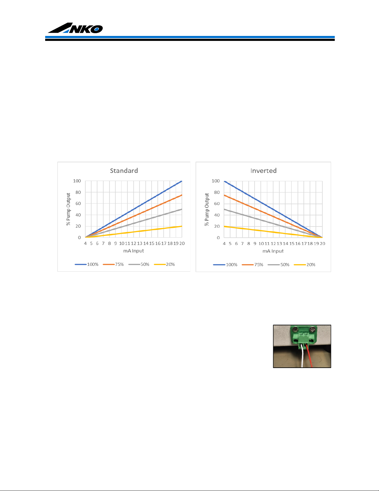
4.2 Adjusting Flow Output
Flow output is controlled by motor speed utilizing the potentiometer. Rates are adjustable from
approximately 5% to 100%. If equipped with a 4-20mA control option, pump speed will vary as the
dedicated input signal changes amplitude. Please refer to Remote Operation below for more details
on 4-20mA operation.
4.3 Remote Operation
Remote Start/Stop – For pump models equipped with remote start/stop, this feature operates by
receiving a dry contact signal and is intended to be connected to a dry contact switch. The input has
no polarity. No voltage is permitted on the input signal. The pump will activate and run while the
switch is closed and deactivate and stop when the switch opens.
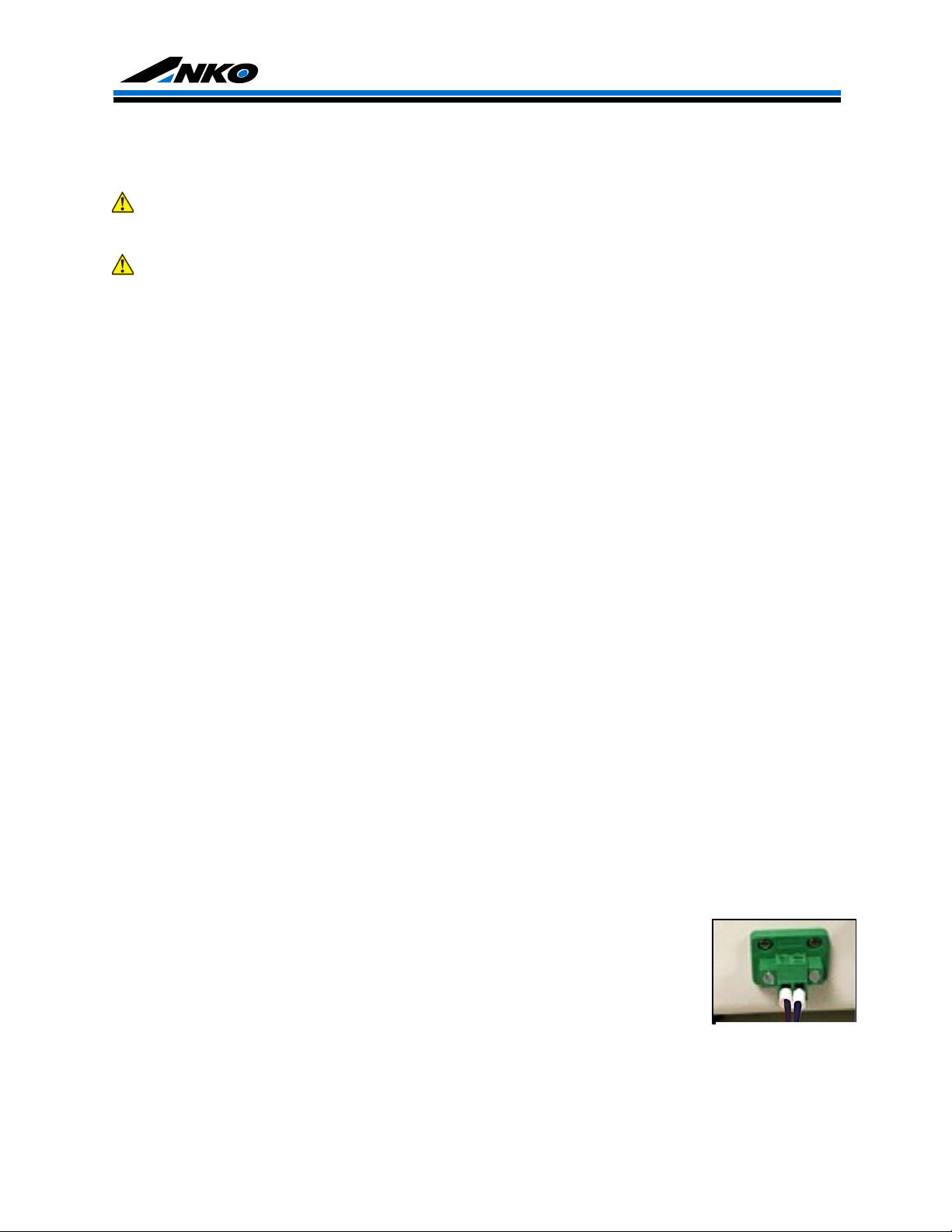
To establish and operate this feature:
1. To activate this feature, install the pair of wires from the dry contact switch
closure device into the terminal block (Figure 1)
2. Set the MODE switch to IN for External mode. The pump will now operate
only when receiving a dry contact signal.
To return the pump local control, set the MODE switch to OUT for Internal mode.