Anritsu MS27101A User manual

Installation Guide
Remote Spectrum Monitors
MS27101A, MS27102A, MS27103A
9 kHz to 6 GHz
Anritsu Company
490 Jarvis Drive
Morgan Hill, CA 95037-2809
USA
http://www.anritsu.com
Part Number: 10580-00409
Revision: C
Published: March 2016
Copyright 2016 Anritsu Company

MS2710xA IG PN: 10580-00409 Rev. C Contents-1
Table of Contents
Chapter 1—MS27101A Installation
1-1 Introduction . . . . . . . . . . . . . . . . . . . . . . . . . . . . . . . . . . . . . . . . . . . . . . . . . 1-1
1-2 Instrument Overview. . . . . . . . . . . . . . . . . . . . . . . . . . . . . . . . . . . . . . . . . . 1-1
Connectors and Chassis . . . . . . . . . . . . . . . . . . . . . . . . . . . . . . . . . . . . 1-2
Mounting Hardware . . . . . . . . . . . . . . . . . . . . . . . . . . . . . . . . . . . . . . . . 1-2
Required Tools . . . . . . . . . . . . . . . . . . . . . . . . . . . . . . . . . . . . . . . . . . . 1-2
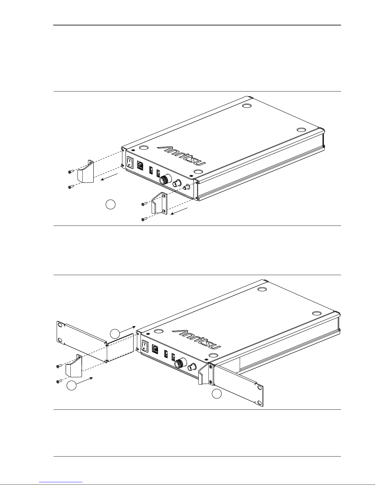
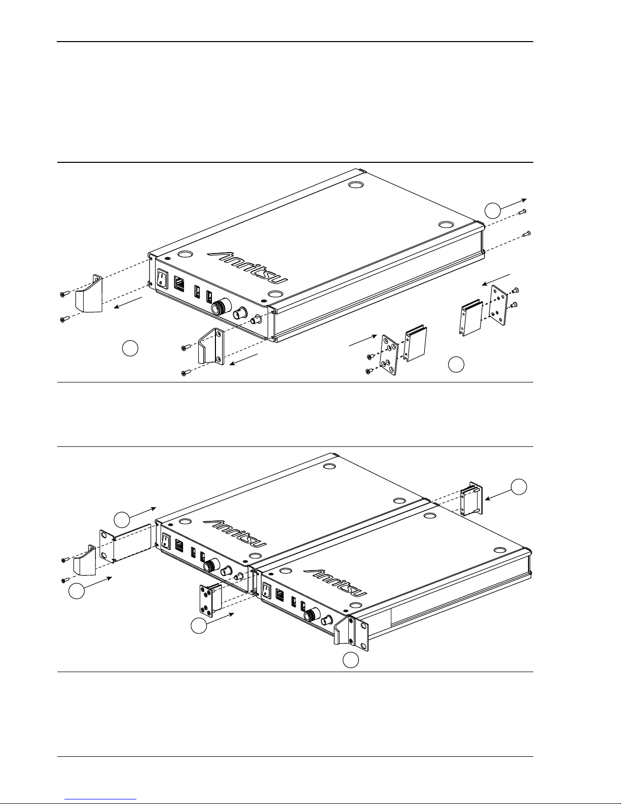
1-3 Single Unit Rack Mounting . . . . . . . . . . . . . . . . . . . . . . . . . . . . . . . . . . . . . 1-3
1-4 Side-by-Side Unit Rack Mounting. . . . . . . . . . . . . . . . . . . . . . . . . . . . . . . . 1-4
Chapter 2—MS27102A Installation
2-1 Introduction . . . . . . . . . . . . . . . . . . . . . . . . . . . . . . . . . . . . . . . . . . . . . . . . . 2-1
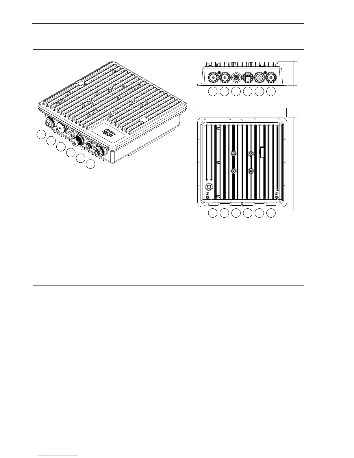
2-2 Instrument Overview. . . . . . . . . . . . . . . . . . . . . . . . . . . . . . . . . . . . . . . . . . 2-1
Connectors and Chassis . . . . . . . . . . . . . . . . . . . . . . . . . . . . . . . . . . . . 2-2
Mounting Hardware . . . . . . . . . . . . . . . . . . . . . . . . . . . . . . . . . . . . . . . . 2-3
Connector Glands . . . . . . . . . . . . . . . . . . . . . . . . . . . . . . . . . . . . . . . . . 2-4
Power Supply . . . . . . . . . . . . . . . . . . . . . . . . . . . . . . . . . . . . . . . . . . . . 2-4
2-3 Surveying the Installation Site . . . . . . . . . . . . . . . . . . . . . . . . . . . . . . . . . . 2-5
Mounting Considerations. . . . . . . . . . . . . . . . . . . . . . . . . . . . . . . . . . . . 2-5
2-4 Required Equipment . . . . . . . . . . . . . . . . . . . . . . . . . . . . . . . . . . . . . . . . . . 2-6
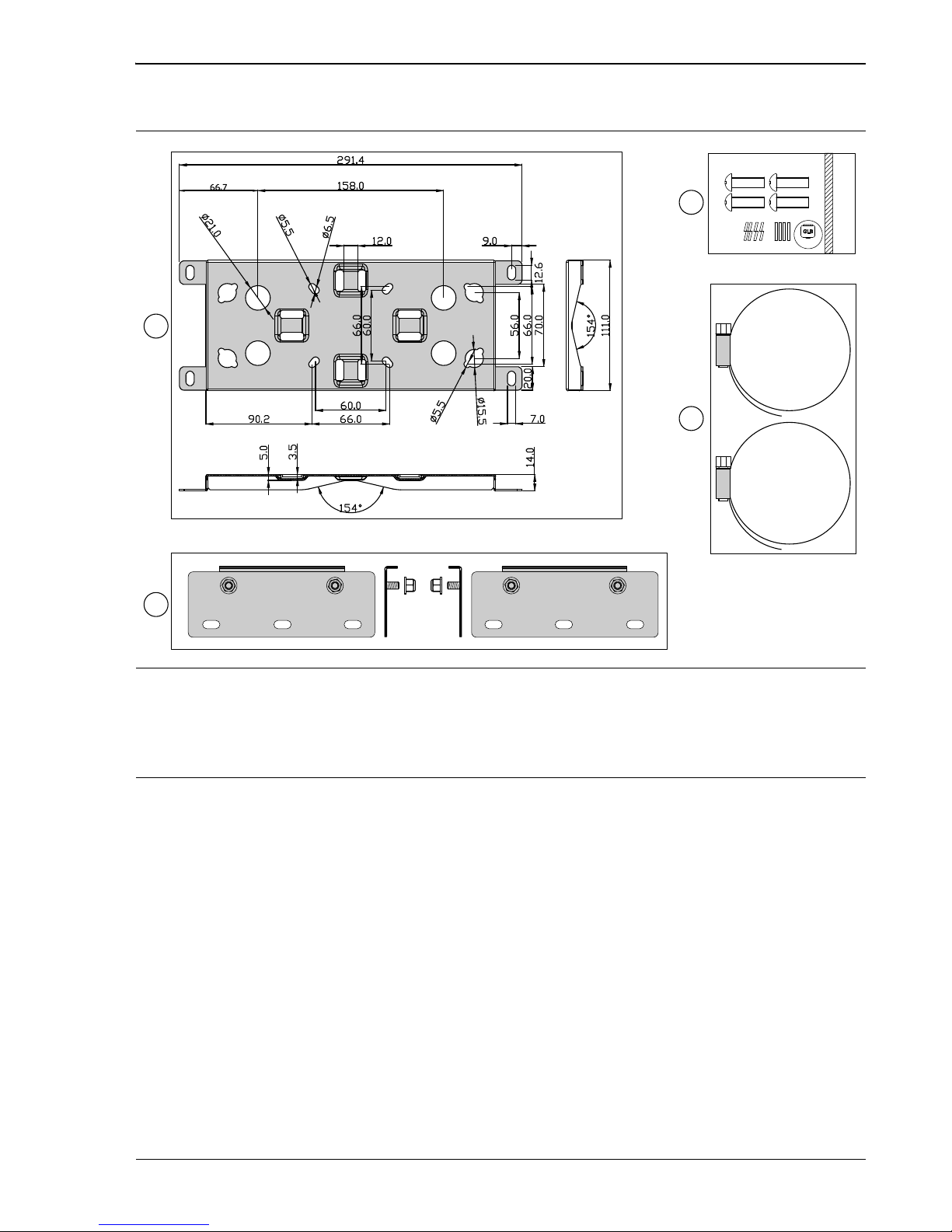
2-5 Installing the Mounting Bracket. . . . . . . . . . . . . . . . . . . . . . . . . . . . . . . . . . 2-6
2-6 Pole and Tower Mounting Instructions . . . . . . . . . . . . . . . . . . . . . . . . . . . . 2-7
2-7 Wall Mounting Instructions . . . . . . . . . . . . . . . . . . . . . . . . . . . . . . . . . . . . . 2-8
2-8 Installing the Antenna Cables. . . . . . . . . . . . . . . . . . . . . . . . . . . . . . . . . . . 2-9
2-9 Installing the Ethernet Cable. . . . . . . . . . . . . . . . . . . . . . . . . . . . . . . . . . . . 2-9
2-10 Installing the Power Supply Cables . . . . . . . . . . . . . . . . . . . . . . . . . . . . . 2-10
Chapter 3—MS27103A Installation
3-1 Introduction . . . . . . . . . . . . . . . . . . . . . . . . . . . . . . . . . . . . . . . . . . . . . . . . . 3-1
3-2 Instrument Overview. . . . . . . . . . . . . . . . . . . . . . . . . . . . . . . . . . . . . . . . . . 3-1
Power Supply . . . . . . . . . . . . . . . . . . . . . . . . . . . . . . . . . . . . . . . . . . . . 3-1
Connectors and Chassis . . . . . . . . . . . . . . . . . . . . . . . . . . . . . . . . . . . . 3-2
Required Tools . . . . . . . . . . . . . . . . . . . . . . . . . . . . . . . . . . . . . . . . . . . 3-2
3-3 MS27103A Rack Mounting . . . . . . . . . . . . . . . . . . . . . . . . . . . . . . . . . . . . . 3-3

MS2710xA IG PN: 10580-00409 Rev. C 1-1
Chapter 1 — MS27101A Installation
1-1 Introduction
The MS27101A remote spectrum monitor can be ordered with optional rack mounting
hardware that allows it to be mounted into a standard 48 cm equipment rack in either a
single unit installation or a side-by-side installation. Section 1-3 describes single unit rack
mounting, Section 1-4 describes side-by-side rack mounting.
The MS27101A must be installed by a trained service person who is familiar with RF system
integration and local regulatory and compliance requirements for the region in which the
instrument is being installed. Read the MS2710xA Product Information, Compliance, and
Safety Guide (PN: 10100-00064) for important safety, legal, and regulatory notices.
For additional information and literature covering your product, visit the product page of
your instrument and select the Library tab:
•http://www.anritsu.com/en-US/test-measurement/products/ms27101a
1-2 Instrument Overview
This section provides a brief overview of the instrument and the supplied accessories.
The MS27101A instrument consists of the following main components:
•MS27101A Remote Spectrum Monitor
•Indoor power supply and power cable
•Optional mounting brackets and fasteners (Option 1)

1-2 Instrument Overview MS27101A Installation
1-2 PN: 10580-00409 Rev. C MS2710xA IG
Connectors and Chassis
Mounting Hardware
Required Tools
The installation requires a medium size Phillips screwdriver.
1. Power Switch
2. Ethernet
3. USB Type A (2)
4. RF Input, N(f)
5. Reference Input, BNC
6. GPS Antenna, SMA(f)
7. Instrument Lock
8. DC Power Input, 5.5 mm Barrel Connector
Figure 1-1. MS27101A Overview
Figure 1-2. MS27101A Optional Rack Mounting Hardware
8
369 mm
42 mm
337 mm
215 mm
2
1
3
5
4
6
7
Single Unit Mounting Brackets Side-by-Side Unit Mounting Brackets

MS27101A Installation 1-3 Single Unit Rack Mounting
MS2710xA IG PN: 10580-00409 Rev. C 1-3
1-3 Single Unit Rack Mounting
This section explains how to fit a single MS27101A monitor into an instrument rack using the
two single mounting brackets.
1. Prepare the MS27101A by removing the front panel handles as shown in Figure 1-3.
Retain the screws.
2. Slide the two mounting brackets into the aluminum extrusions as shown in
Figure 1-4 (1), then reinstall the front panel handles (2 and 3) using the same screws
that were removed in Step 1.
3. Install finished assembly into the rack mount per the cabinet manufacturers
instructions.
Figure 1-3. Preparing the MS27101A for Single Unit Rack Mounting
Figure 1-4. Installing the MS27101A Mounting Brackets
1
1
2
3

1-4 Side-by-Side Unit Rack Mounting MS27101A Installation
1-4 PN: 10580-00409 Rev. C MS2710xA IG
1-4 Side-by-Side Unit Rack Mounting
This section explains how to fit two MS27101A remote spectrum monitors into an instrument
rack using the side-by-side mounting brackets.
1. Prepare both MS27101A instruments by removing the front panel handles and inside
rear panel screws as shown in Figure 1-5 (1 and 2). Retain the screws.
2. Assemble the inside mounting bracket as shown in Figure 1-5 (3)
3. Slide the mounting brackets into the aluminum extrusions as shown in
Figure 1-6 (1 and 3), then reinstall the front panel handles (2 and 4) using the same
screws that were removed in Step 1.
4. Install finished assembly into the rack mount per the cabinet manufacturers
instructions.
Figure 1-5. Preparing the MS27101A for Side-by-Side Rack Mounting
Figure 1-6. Installing the MS27101A Side-by-Side Mounting Brackets
3
1
2
1
2
3
3
4

MS2710xA IG PN: 10580-00409 Rev. C 2-1
Chapter 2 — MS27102A Installation
2-1 Introduction
This chapter provides:
•a brief overview of the MS27102A Remote Spectrum Monitor
•installation considerations and required equipment
•considerations when selecting a location to install the remote spectrum monitor
•instructions for installing the instrument to either a pole or wall
The MS27102A must be installed by a trained service person who is familiar with RF system
integration and local regulatory and compliance requirements for the region in which the
instrument is being installed. Read the MS2710xA Product Information, Compliance, and
Safety Guide (PN: 10100-00064) for important safety, legal, and regulatory notices.
For additional information and literature covering your product, visit the product page of
your instrument and select the Library tab:
•http://www.anritsu.com/en-US/test-measurement/products/ms27102a
2-2 Instrument Overview
This section provides a brief overview of the instrument and the supplied accessories.
The MS27102A instrument consists of the following main components:
•MS27102A Remote Spectrum Monitor
•Mounting brackets and fasteners
•IP67 Ethernet and power connector glands
•Indoor power supply and power cable with assembled connector gland
•GPS antenna
Caution
Safe and reliable installation must follow the local electrical and building
regulations. In the United States, the National Electrical Code (NEC) is the
generally adopted standard. Verify that the installation follows the NEC or your
local regulations.

2-2 Instrument Overview MS27102A Installation
2-2 PN: 10580-00409 Rev. C MS2710xA IG
Connectors and Chassis
1. GPS Antenna, SMA(f)
2. No Connection
3. 3-pin Power Input (see “Power Supply Gland Assembly” on page 2-10)
4. Ethernet (see “Ethernet Gland Assembly” on page 2-9)
5. RF Input Port 2, N(f) (optional)
6. RF Input Port 1, N(f)
Figure 2-1. MS27102A Overview
2 135 4
6
2 135 4
6
2
1
3
5
4
6
310 mm
310 mm 81.4 mm

MS27102A Installation 2-2 Instrument Overview
MS2710xA IG PN: 10580-00409 Rev. C 2-3
Mounting Hardware
1. Universal mounting bracket detail
2. Mounting bracket extensions and nuts (6 mm hex nuts, 2 each, used for wall mounting only)
3. Stainless machine screw set (10 mm M6 x 0.8, 4 each)
4. Stainless strap clamps (101 mm maximum diameter, 2 each)
Figure 2-2. MS27102A Mounting Hardware
3
4
1
2
M6

2-2 Instrument Overview MS27102A Installation
2-4 PN: 10580-00409 Rev. C MS2710xA IG
Connector Glands
The figure below illustrates the IP67 rated Ethernet (top) and power connector (bottom) gland
assemblies.
Power Supply
The MS27102A Remote Spectrum Monitor comes with an indoor AC/DC power converter with
a pre-assembled power cable and gland. This is to be used only for indoor applications. For
outdoor usage, a DC power supply must be supplied by the user and must meet the following
criteria:
• Voltage rating: 11 VDC to 24 VDC (supplied at instrument connector)
• Power dissipation: 11 W
• Environmental ratings: IP67 rating recommended or otherwise suitable outdoor
supply, including supply cabling
•Powercabling:appropriate weather resistant cabling with adequately sized
conductors for the length of run and power demand. The provided connector has screw
terminals and will work for wire sizes from 14 AWG to 18 AWG with an outside cable
diameter of 5.5 mm to 8.0 mm (0.22 to 0.31 in).
1. O-ring
2. Housing with connector pins
3. Lock nut
4. Gasket
5. Connector body
6. Seals
7. Inner collet clip
8. Sealing nut
Figure 2-3. Ethernet and Power Connector Gland Assemblies
6 7 81 2 3 4 5
Other manuals for MS27101A
1
This manual suits for next models
2
Table of contents


