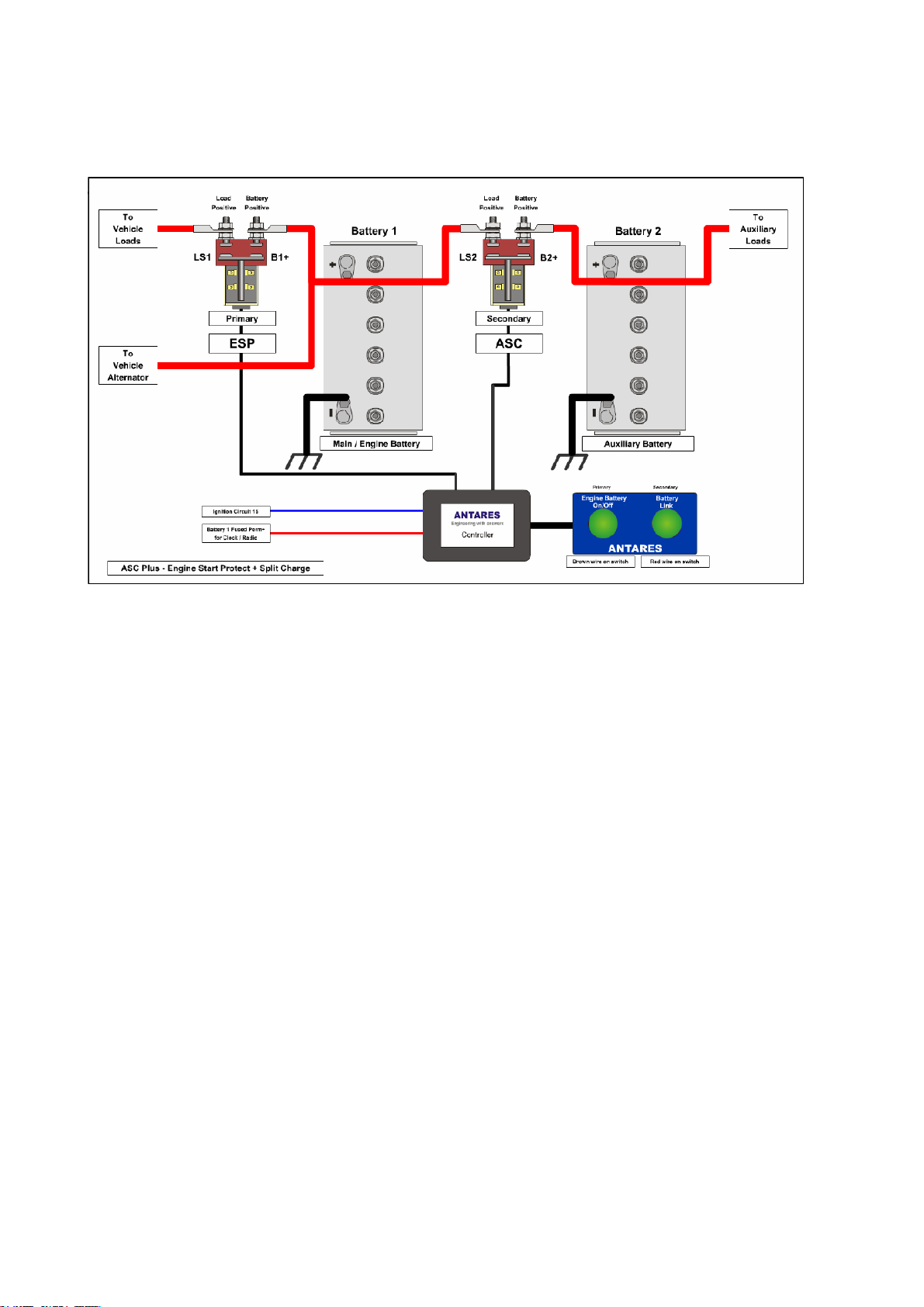
ASC+ System Auto Split Charge & Engine Start Protect
User Guide and Installation Instructions
Document No 13362 Issue 04 Page 3 of 21
IMPORTANT SAFETY INFORMATION
Please read and observe the installation instructions.
WARNING: Explosive gasses may be generated by a battery on charge. To prevent
ignition, allow time for gasses to disperse before attempting to connect this unit.
When systems which affect the driver’s control of the vehicle are powered from the
protected battery, the system’s blue “ignition” input must be connected – its function
is to inhibit battery isolation while the vehicle is being driven.
Wiring protection:
It is the responsibility of the system installer to ensure that steps are taken to
minimise the risk of fire & other hazards in the event of a wiring fault.
The ASC+’s control wiring is protected by systems within the ASC+ itself, provided all
external control wiring is of 0.75mm2cross section or greater.
The high current power circuits are not internally protected & measures must be taken
to limit or interrupt any fault current which may occur within the ASC+ or the
connected power wiring. The best way to provide this protection is normally by fusing
at the source of the potential fault current, which in most cases is the connected
vehicle battery. Bear in mind that any fuses may have to carry cranking current & may
also be required to carry the maximum alternator output without rupture. In most 12
volt van applications, a 350amp MEGA fuse on the starter battery & a 300amp Antares
stud fuse on the auxiliary batteries will be sufficient.
Type Approval – Information (APPROVAL PENDING)
Concerning directive 72/245/EEC as amended by 95/54/EC & last amended by directive
2006/28/EC;
Conditions of use for which the type approval (e mark) applies:
This equipment is designated as an electronic sub-assembly;
It is intended for use on-board road-going vehicles;
Engine start battery protection systems are intended to be connected directly to a vehicle
engine starting battery and to be used to disconnect the battery’s loads so as to preserve
charge for engine starting.
Auxiliary battery protection systems are intended to be connected directly to a vehicle’s
auxiliary battery (Auxiliary batteries are those which cannot affect the driver’s control of the vehicle) and to
be used to disconnect the battery’s loads so as to provide deep-discharge protection when
no useable capacity remains.