(800) 952-7655 • www.rollnlock.com
page 8
S
TEP
10:
OPENING AND CLOSING / ADJUSTING THE
HINGED LID
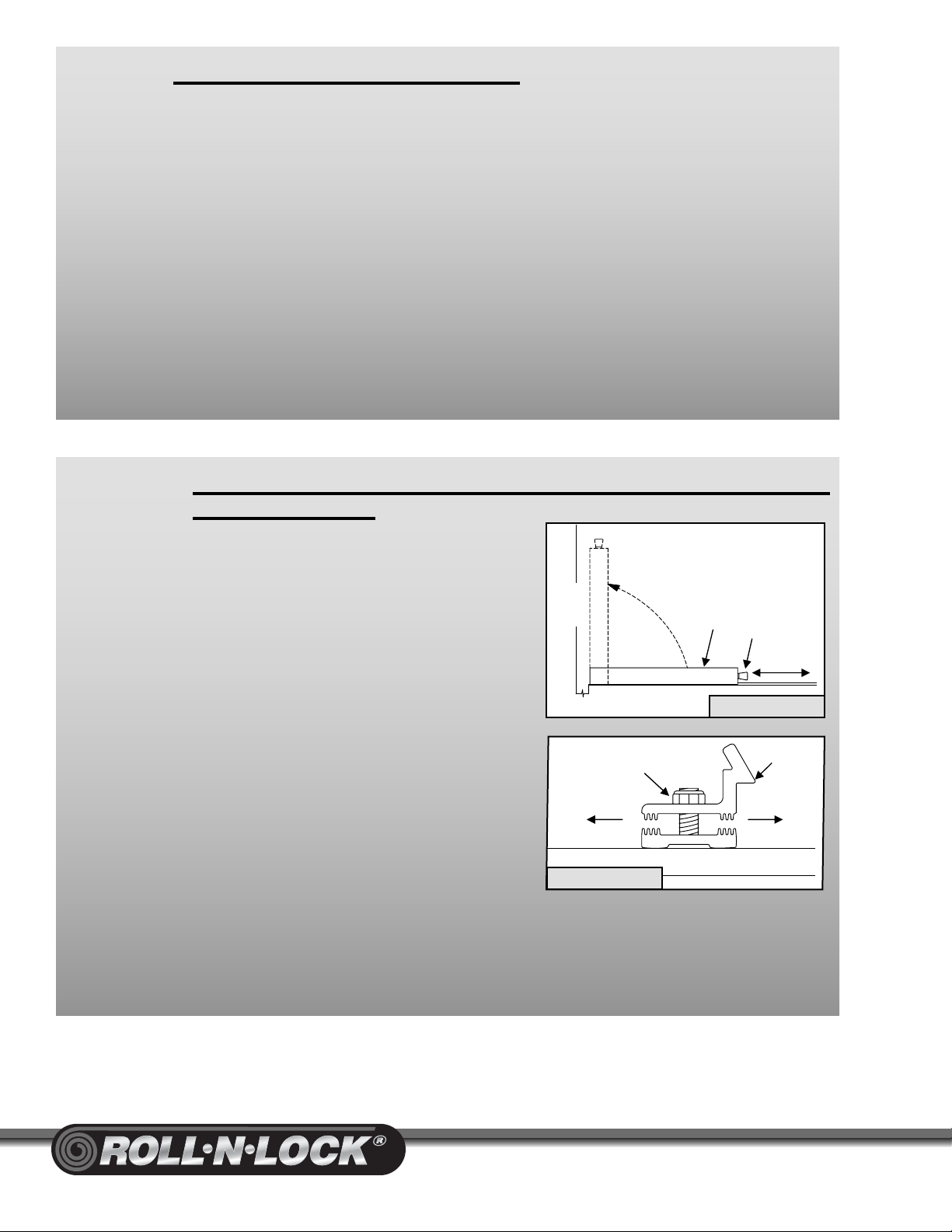
To Open:
A.
Grasp the Latch Pin Knobs, pull out and turn knobs
90° to hold Pin in the unlock position.Grasp the Lid
and lift. Rest the Lid against the back of the cab to
hold open for service or cleaning
(Diagram 28)
.
To Close:
A.
Lower the Lid and return the Latch Pins to locked
position by turning the knobs 1/4 turn.
If Lid is loose:
A.
Raise Lid and loosen the nylock nut on each Lid Latch
Bracket, move the top half of the Bracket one notch
toward the tailgate. Tighten both nuts and close Lid
(Diagram 29)
.
If Lid is tight:
A.
Raise Lid and loosen the nylock nut on each Lid
Latch Bracket, move the top half of the Bracket one
notch toward the Housing. Tighten both nuts and close Lid
(Diagram 29)
. Repeat if futher
adjustments are needed.
S
TEP
9:
TEST UNIT OPERATION
In Step 9 the Cover was opened (retracted). This should have caused the Lock Lever to
enter the Lock Pocket and rotate to the 7 o’clock (latched) position.
A.
To close the Cover, pull the Pull-Strap hand-over hand, allowing the excess strap to fall
into the bed until you can reach the Handle. Place your hands evenly spread on the Handle
and pull the Handle until it contacts the Tailgate Extrusion. As the Handle contacts the
Tailgate Extrusion the spring loaded Latches (which were energized when the Cover was
retracted) will automatically trip, simultaneously latching the Cover to the tailgate and side
Tracks.
B.
To open the Cover, pull back slightly on the Handle to relieve spring tension from the
Latch Mechanisms and turn the Lock Lever clockwise to the 10 o’clock position. The
Cover should retract on its own with only a slight push to set it into motion. When the
Cover is retracting it is best to hold the Pull-Strap and allow it to slip through your fingers
as the Cover travels. Applying pressure to the Pull-Strap as it slips through your fingers
will act as a braking action, preventing the Handle from slamming into the Lid at high
speed. The Cover must retract with only enough force to rotate and reset the Lock Lever
and Latching Mechanism.
Lid Knob
Back
of
Cab
Diagram 28
Diagram 29