APPLICATION
The DC Line Charger is intended for the harging of auxiliary batteries on-board road-going
vehi les. It is parti ularly suited to harging trailer batteries, where power is supplied through
the 12S or 24S “suzi” so ket, & urrent needs to be onstrained to avoid overloading the
so ket & its supply ables. The model range provides for 12volt, 24 volt & mixed voltage
systems.
The unit is a tivated automati ally by the presen e of a harging sour e on the input supply,
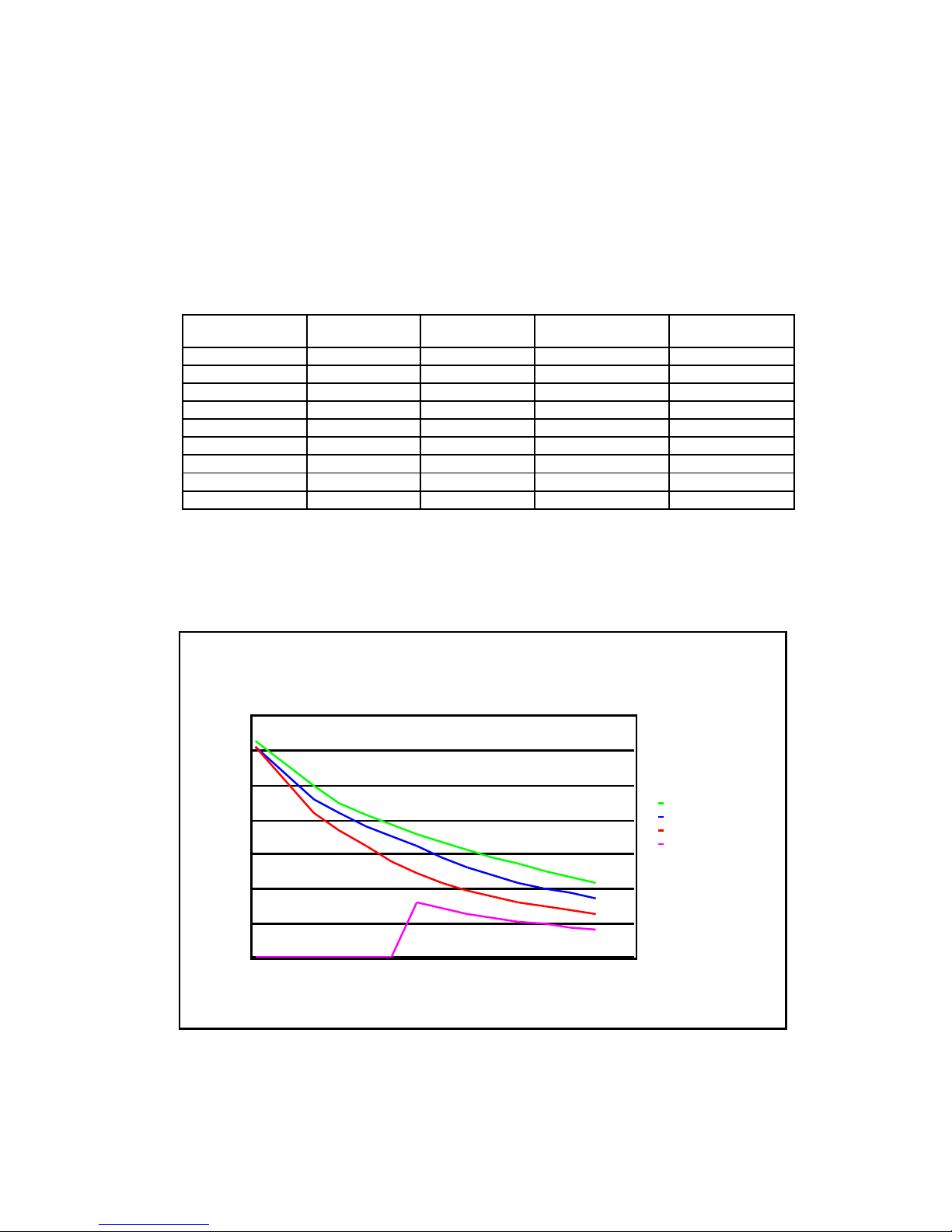
swit hing off again when the harging sour e is removed. Charging output is temperature
ompensated, with raised voltage during re harge, automati ally swit hing to float voltage
on e the battery has re overed. The presen e of a load on the battery whilst harging does
not pose a problem, although any load should be apable of withstanding the raised harging
voltage, whi h ould be as high as 15 or 30 volts (12 or 24 volt systems) under some
ir umstan es.
TYPE APPROVAL – INFORMATION (APPROVAL PENDING)
Con erning dire tive 72/245/EEC as last amended by dire tive 95/54/EC;
Conditions of use for whi h the type approval (E mark) applies:
This equipment is designated as an ele troni sub-assembly;
It is intended for use on-board road-going vehi les;
This equipment is intended to be onne ted dire tly to a vehi le 12 or 24 volt DC supply and
used to harge a separate 12 or 24 volt lead a id battery.
Note that non-vehi ular & marine appli ations are spe ifi ally ex luded, as the DC line
harger has not been verified against the parti ular EMC standards that apply.
Non approved onditions of use:
This unit may be suitable for use in other appli ations, but it an only be supplied as a
omponent in this respe t, in whi h ase the type approval does not apply. If the unit is
used in this way, then it is supplied solely on the ondition that it is the responsibility of
the manufa turer of the apparatus to ensure that the apparatus omplies with the
requirements of the relevant legislation, and apply the CE marking should it be required.
In this ase, this user manual does not apply, and referen e should be made to Antares
(Europe) Limited for any information required for omplian e with the legislation.
IMPORTANT SAFETY INFORMATION
Please read and observe the installation instru tions.
WARNING: Explosive asses may be enerated by a battery on char e. To prevent
i nition, allow time for asses to disperse before attemptin to connect this unit.
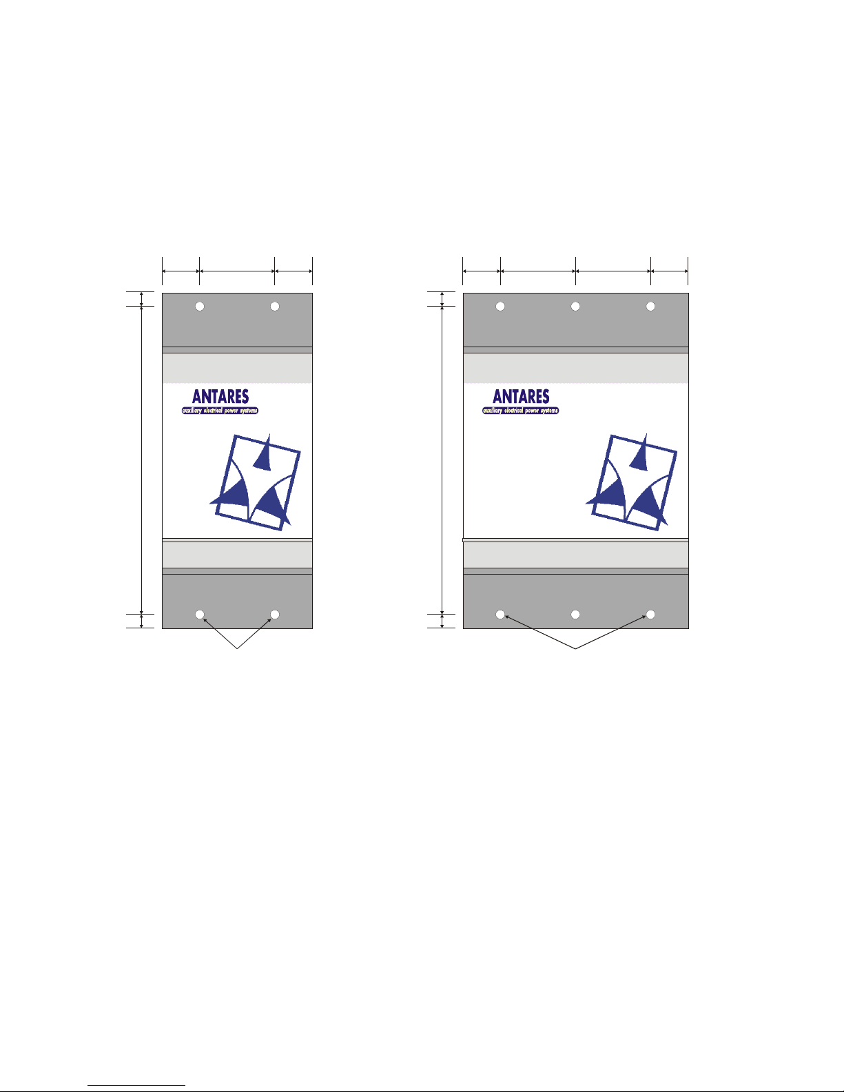
INSTALLATION
Choosin a location
The DC harger is suitable for use in a sheltered lo ation only, and must not be exposed to
the outside environment, water spray or areas where ondensation is likely. Areas subje t to
high temperature or vibration must also be avoided if performan e and reliability are not to
be impaired.
DC Charger User Manual, Part No. 13328 Issue 5